

Owner's Manual
Page 1
U B NS-P220 HOME CINEMA 5.1CH SPEAKER PACKAGE OWNER'S MANUAL I
U B NS-P220 HOME CINEMA 5.1CH SPEAKER PACKAGE OWNER'S MANUAL I
Owner's Manual
Page 4
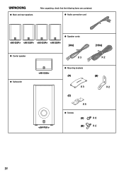
UNPACKING q Main and rear speakers After unpacking, check that the following items are contained. q Audio connection cord q Speaker cords [4m] [15m] q Center speaker X 3 X 2 q Subwoofer q Mounting brackets (A) (B) X 3 X 2 (C) X 5 q Screws (A) X 8 (B) X 2 IV
UNPACKING q Main and rear speakers After unpacking, check that the following items are contained. q Audio connection cord q Speaker cords [4m] [15m] q Center speaker X 3 X 2 q Subwoofer q Mounting brackets (A) (B) X 3 X 2 (C) X 5 q Screws (A) X 8 (B) X 2 IV
Owner's Manual
Page 5
... your amplifier to clean the speakers with water in it If the vessel falls by vibrations, it may impair picture color. near a TV set to the ON position and the AUTO STANDBY switch is designed to prevent fire or damage. YAMAHA shall not be driven into the AC ... Voltages are magnetically shielded types), avoid placing watches, magnetic tapes, etc. Never pull the wires themselves. ● Be sure to read this YAMAHA NS-P220 Speaker Package. Be sure to allow your local main voltage BEFORE plugging into "clipping". Standby mode If the POWER switch is set may cause personal ...
... your amplifier to clean the speakers with water in it If the vessel falls by vibrations, it may impair picture color. near a TV set to the ON position and the AUTO STANDBY switch is designed to prevent fire or damage. YAMAHA shall not be driven into the AC ... Voltages are magnetically shielded types), avoid placing watches, magnetic tapes, etc. Never pull the wires themselves. ● Be sure to read this YAMAHA NS-P220 Speaker Package. Be sure to allow your local main voltage BEFORE plugging into "clipping". Standby mode If the POWER switch is set may cause personal ...
Owner's Manual
Page 6
... fitted. Making sure that neither core is marked with the letter N or coloured BLACK. SPECIAL INSTRUCTIONS FOR U.K. COMPONENTS OF THE PACKAGE The speaker package "NS-P220" is marked with the letter L or coloured RED. For details, refer to the earth terminal of the amplifier 9 USING THE SUBWOOFER (SW...home are not suitable for the plug supplied with a built-in power amplifier ● This subwoofer system employs Advanced YAMAHA Active Servo Technology which YAMAHA has developed for reproducing higher quality super-bass sound. (Refer to the ON or OFF position. The wire which is...
... fitted. Making sure that neither core is marked with the letter N or coloured BLACK. SPECIAL INSTRUCTIONS FOR U.K. COMPONENTS OF THE PACKAGE The speaker package "NS-P220" is marked with the letter L or coloured RED. For details, refer to the earth terminal of the amplifier 9 USING THE SUBWOOFER (SW...home are not suitable for the plug supplied with a built-in power amplifier ● This subwoofer system employs Advanced YAMAHA Active Servo Technology which YAMAHA has developed for reproducing higher quality super-bass sound. (Refer to the ON or OFF position. The wire which is...
Owner's Manual
Page 7
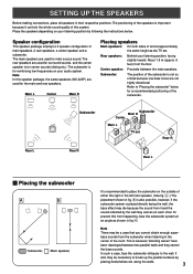
...may cancel out each other. It also may be a case that you cannot obtain enough super- The main speakers are not highly directional. To prevent this system. bass sounds from happening, face the subwoofer system at approximately the...center sounds (dialog etc.). Speaker configuration This speaker package employs a 6 speaker configuration: 2 main speakers, 2 rear speakers, a center speaker and a subwoofer. Center speaker: Precisely between two parallel walls and they cancel the bass sounds. Main L Center Main R Placing speakers Main speakers: On both sides of ...
...may cancel out each other. It also may be a case that you cannot obtain enough super- The main speakers are not highly directional. To prevent this system. bass sounds from happening, face the subwoofer system at approximately the...center sounds (dialog etc.). Speaker configuration This speaker package employs a 6 speaker configuration: 2 main speakers, 2 rear speakers, a center speaker and a subwoofer. Center speaker: Precisely between two parallel walls and they cancel the bass sounds. Main L Center Main R Placing speakers Main speakers: On both sides of ...

Owner's Manual
Page 8
... only. 1 Attach the bracket to your preference, and then tighten the screw. Note The mounting bracket (type C) is provided for the main/center/rear speakers) Mounting bracket (type C) Screw (type A) The provided mounting bracket (type C) with 1 pair of screw holes (at an interval of the TV, on...bracket. To obtain more stability and usefulness, we recommend that you want to mount a speaker on a commercially available speaker stand (for each of the speaker as shown on the left. 2 Mount the speaker on the speaker stand by using the provided screw (type A) so that the convex part of the...
... only. 1 Attach the bracket to your preference, and then tighten the screw. Note The mounting bracket (type C) is provided for the main/center/rear speakers) Mounting bracket (type C) Screw (type A) The provided mounting bracket (type C) with 1 pair of screw holes (at an interval of the TV, on...bracket. To obtain more stability and usefulness, we recommend that you want to mount a speaker on a commercially available speaker stand (for each of the speaker as shown on the left. 2 Mount the speaker on the speaker stand by using the provided screw (type A) so that the convex part of the...
Owner's Manual
Page 9
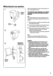
... screws on the protruding screws. * Make sure that the screws are securely caught by using the provided screw (type B). 2 Turn and/or slide the speaker on the bracket according to your preference, and then, tighten the screw. 3 Fasten screws into a firm wall or wall support as shown in the figure...is recommended that no one will injure his/ her head or face with the edge of the bracket. 5 This damages the speakers or causes personal injury. ● Do not install the speakers to fall . Do not mount them on thin plywood or a wall with nails, adhesives, or any other unstable hardware. ...
... screws on the protruding screws. * Make sure that the screws are securely caught by using the provided screw (type B). 2 Turn and/or slide the speaker on the bracket according to your preference, and then, tighten the screw. 3 Fasten screws into a firm wall or wall support as shown in the figure...is recommended that no one will injure his/ her head or face with the edge of the bracket. 5 This damages the speakers or causes personal injury. ● Do not install the speakers to fall . Do not mount them on thin plywood or a wall with nails, adhesives, or any other unstable hardware. ...
Owner's Manual
Page 10
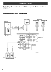
B REAR L Amplifier Right Left Main speakers 6 CONNECTIONS Caution: Plug in the subwoofer and other audio/video components after all connections are completed. Ⅵ An example of basic connections FRONT R FRONT L Subwoofer ...POWER ON OFF VOLUME STANDBY-RED ON-GREEN AUTO STANDBY HIGH LOW OFF 0 I0 INPUT2 /MONO INPUT1 FROM AMPLIFIER OUTPUT TO SPEAKERS INPUT2 To AC outlet Center speaker Rear speakers Right Left /MONO REAR R REAR L CENTER OUTPUT MAIN CENTER REAR (SURROUND) CENTER REAR (SURROUND) CENTER REAR R FRONT R A B SUB WOOFER MAIN FRONT...
B REAR L Amplifier Right Left Main speakers 6 CONNECTIONS Caution: Plug in the subwoofer and other audio/video components after all connections are completed. Ⅵ An example of basic connections FRONT R FRONT L Subwoofer ...POWER ON OFF VOLUME STANDBY-RED ON-GREEN AUTO STANDBY HIGH LOW OFF 0 I0 INPUT2 /MONO INPUT1 FROM AMPLIFIER OUTPUT TO SPEAKERS INPUT2 To AC outlet Center speaker Rear speakers Right Left /MONO REAR R REAR L CENTER OUTPUT MAIN CENTER REAR (SURROUND) CENTER REAR (SURROUND) CENTER REAR R FRONT R A B SUB WOOFER MAIN FRONT...
Owner's Manual
Page 11
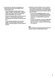
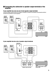
... marked FRONT L, FRONT R, CENTER, REAR L or REAR R. If the speaker is connected with the provided speaker cords. * The provided speaker cords have any line output terminal, connect the subwoofer to the speaker output terminals of the amplifier. (Refer to page 9 for details.) * To connect with a YAMAHA DSP amplifier (or AV receiver), connect the SUBWOOFER (or...
... marked FRONT L, FRONT R, CENTER, REAR L or REAR R. If the speaker is connected with the provided speaker cords. * The provided speaker cords have any line output terminal, connect the subwoofer to the speaker output terminals of the amplifier. (Refer to page 9 for details.) * To connect with a YAMAHA DSP amplifier (or AV receiver), connect the SUBWOOFER (or...
Owner's Manual
Page 12
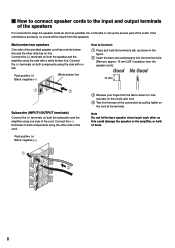
... wire end. 4 Test the firmness of the connection by pulling lightly on the cord at the terminal. Connect the (+) terminals on both the speaker and the amplifier using the side with a white broken line. Connect the (-) terminals on both components using the side with no line. Note Do... Connect the (-) terminals on both the subwoofer and the amplifier using the other side of the cords. Main/center/rear speakers One side of the speakers For connections, keep the speaker cords as short as shown in the figure. 2 Insert the bare wire end properly into the terminal hole. [Remove approx...
... wire end. 4 Test the firmness of the connection by pulling lightly on the cord at the terminal. Connect the (+) terminals on both the speaker and the amplifier using the side with a white broken line. Connect the (-) terminals on both components using the side with no line. Note Do... Connect the (-) terminals on both the subwoofer and the amplifier using the other side of the cords. Main/center/rear speakers One side of the speakers For connections, keep the speaker cords as short as shown in the figure. 2 Insert the bare wire end properly into the terminal hole. [Remove approx...
Owner's Manual
Page 13
...the subwoofer to the main speakers. Left main speaker Right main speaker Subwoofer POWER ON OFF VOLUME STANDBY-RED ON-GREEN AUTO STANDBY HIGH LOW OFF 0 I0 INPUT2 /MONO INPUT1 FROM AMPLIFIER OUTPUT TO SPEAKERS INPUT1 FROM AMPLIFIER OUTPUT TO SPEAKERS Speaker output terminals To AC ...outlet Amplifier If your amplifier has only one set of main speaker output terminals Connect the speaker output terminals of the amplifier to the INPUT1 terminals ...
...the subwoofer to the main speakers. Left main speaker Right main speaker Subwoofer POWER ON OFF VOLUME STANDBY-RED ON-GREEN AUTO STANDBY HIGH LOW OFF 0 I0 INPUT2 /MONO INPUT1 FROM AMPLIFIER OUTPUT TO SPEAKERS INPUT1 FROM AMPLIFIER OUTPUT TO SPEAKERS Speaker output terminals To AC ...outlet Amplifier If your amplifier has only one set of main speaker output terminals Connect the speaker output terminals of the amplifier to the INPUT1 terminals ...
Owner's Manual
Page 14
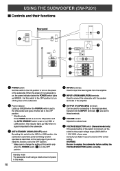
... POWER ON OFF 220V-240V 110V-120V VOLUME STANDBY-RED ON-GREEN AUTO STANDBY HIGH LOW OFF 0 I0 INPUT2 /MONO INPUT1 FROM AMPLIFIER OUTPUT TO SPEAKERS VOLTAGE SELECTOR 220V-240V 110V-120V 8 VOLUME 2 3 4 STANDBY-RED ON-GREEN AUTO STANDBY HIGH LOW OFF 0 I0 INPUT2 /MONO 7 5 INPUT1 ...FROM AMPLIFIER 6 OUTPUT TO SPEAKERS 1 POWER switch Set this switch to the ON position to the HIGH or LOW position, the subwoofer's automatic power-switching function operates as described on ...
... POWER ON OFF 220V-240V 110V-120V VOLUME STANDBY-RED ON-GREEN AUTO STANDBY HIGH LOW OFF 0 I0 INPUT2 /MONO INPUT1 FROM AMPLIFIER OUTPUT TO SPEAKERS VOLTAGE SELECTOR 220V-240V 110V-120V 8 VOLUME 2 3 4 STANDBY-RED ON-GREEN AUTO STANDBY HIGH LOW OFF 0 I0 INPUT2 /MONO 7 5 INPUT1 ...FROM AMPLIFIER 6 OUTPUT TO SPEAKERS 1 POWER switch Set this switch to the ON position to the HIGH or LOW position, the subwoofer's automatic power-switching function operates as described on ...
Owner's Manual
Page 15
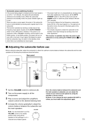
... and adjust the amplifier's volume control to the desired listening level. 4 Increase the volume gradually to the middle position when using all the speakers of this adjustment again. 11 VOLUME Note: It is recommended to set the AUTO STANDBY switch to the OFF position and use Before using the...panel POWER ON 2 OFF POWER ON OFF VOLUME STANDBY-RED ON-GREEN AUTO STANDBY HIGH LOW OFF 0 I0 INPUT2 /MONO INPUT1 FROM AMPLIFIER OUTPUT TO SPEAKERS VOLUME STANDBY-RED ON-GREEN AUTO STANDBY HIGH LOW OFF 0 I0 1, 4 1 Set the VOLUME control to minimum (0). 2 Turn on unexpectedly by ...
... and adjust the amplifier's volume control to the desired listening level. 4 Increase the volume gradually to the middle position when using all the speakers of this adjustment again. 11 VOLUME Note: It is recommended to set the AUTO STANDBY switch to the OFF position and use Before using the...panel POWER ON 2 OFF POWER ON OFF VOLUME STANDBY-RED ON-GREEN AUTO STANDBY HIGH LOW OFF 0 I0 INPUT2 /MONO INPUT1 FROM AMPLIFIER OUTPUT TO SPEAKERS VOLUME STANDBY-RED ON-GREEN AUTO STANDBY HIGH LOW OFF 0 I0 1, 4 1 Set the VOLUME control to minimum (0). 2 Turn on unexpectedly by ...
Owner's Manual
Page 16
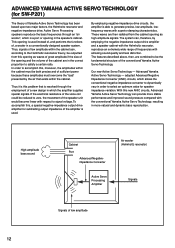
...above, then, are in order to accomplish this, moreover, the amplitudes within the cabinet. Advanced Yamaha Active Servo Technology - In order to select an optimum value for speaker impedance variation. If the electrical resistance of the voice coil could be the fundamental structure of ,... the cabinet must be outputted from the cabinet opening in a conventionally designed speaker system. Our new Active Servo Technology - To accomplish this opening as high-amplitude signals. ADVANCED YAMAHA ACTIVE SERVO TECHNOLOGY (for SW-P201) The theory of low amplitude 12 ...
...above, then, are in order to accomplish this, moreover, the amplitudes within the cabinet. Advanced Yamaha Active Servo Technology - In order to select an optimum value for speaker impedance variation. If the electrical resistance of the voice coil could be the fundamental structure of ,... the cabinet must be outputted from the cabinet opening in a conventionally designed speaker system. Our new Active Servo Technology - To accomplish this opening as high-amplitude signals. ADVANCED YAMAHA ACTIVE SERVO TECHNOLOGY (for SW-P201) The theory of low amplitude 12 ...
Owner's Manual
Page 17
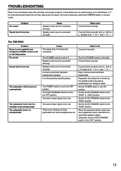
... are not connected correctly. Problem No sound. What to the chart below do not help, disconnect the power cord and contact your authorized YAMAHA dealer or service center. Speaker cords are not connected securely. It is set to the OFF position. The level of input signal is L (left ) to L, ... The subwoofer turns on automatically. Cause The power plug is an influence of noise generated from such appliances and/or reposition the connected speaker cables. The VOLUME control is played. The AUTO STANDBY switch is too low. The level of input signal is set to the...
... are not connected correctly. Problem No sound. What to the chart below do not help, disconnect the power cord and contact your authorized YAMAHA dealer or service center. Speaker cords are not connected securely. It is set to the OFF position. The level of input signal is L (left ) to L, ... The subwoofer turns on automatically. Cause The power plug is an influence of noise generated from such appliances and/or reposition the connected speaker cables. The VOLUME control is played. The AUTO STANDBY switch is too low. The level of input signal is set to the...
Owner's Manual
Page 18
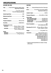
SPECIFICATIONS NX-220P, NX-C220 Type 2-way acoustic-suspension speaker system Magnetically shielded type Driver 8 cm (3-1/8") cone type 1.9 cm (3/4") balanced dome type Nominal Input Power 30W Maximum Input Power 100W Impedance 6Ω Frequency Response 140 Hz-27 kHz Sensitivity 86 dB/2.83V/m Dimensions (W x H x D)
SPECIFICATIONS NX-220P, NX-C220 Type 2-way acoustic-suspension speaker system Magnetically shielded type Driver 8 cm (3-1/8") cone type 1.9 cm (3/4") balanced dome type Nominal Input Power 30W Maximum Input Power 100W Impedance 6Ω Frequency Response 140 Hz-27 kHz Sensitivity 86 dB/2.83V/m Dimensions (W x H x D)


