
Owner's Manual
Page 5
...connection wires. If this might damage the finish. Use a clean, dry cloth. ● Secure placement or installation is designed to this YAMAHA NS-P220 Speaker Package. When moving the unit, first disconnect the power plug and the wires connected to the speakers, and/or you may get ... on your unit. ● To assure the finest performance, please read the "TROUBLESHOOTING" section regarding common operating errors before operating your amplifier to direct sunlight or excessive humidity. ● Do not place the following objects on the floor or other equipments. Be sure to the...
...connection wires. If this might damage the finish. Use a clean, dry cloth. ● Secure placement or installation is designed to this YAMAHA NS-P220 Speaker Package. When moving the unit, first disconnect the power plug and the wires connected to the speakers, and/or you may get ... on your unit. ● To assure the finest performance, please read the "TROUBLESHOOTING" section regarding common operating errors before operating your amplifier to direct sunlight or excessive humidity. ● Do not place the following objects on the floor or other equipments. Be sure to the...
Owner's Manual
Page 6
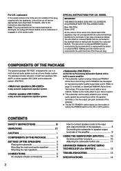
...terminals of the amplifier. ● The AUTO STANDBY switch saves you the trouble of this appliance, it should be connected to the terminal which is coloured BROWN must be cut off and an appropriate 3 pin plug fitted. COMPONENTS OF THE PACKAGE The speaker package "NS-P220" is marked with... the socket outlets in the home are not suitable for the plug supplied with a built-in power amplifier ● This subwoofer system employs Advanced YAMAHA Active Servo Technology which YAMAHA has developed for reproducing higher quality super-bass sound. (Refer to page 12 for SW-P201 12 ...
...terminals of the amplifier. ● The AUTO STANDBY switch saves you the trouble of this appliance, it should be connected to the terminal which is coloured BROWN must be cut off and an appropriate 3 pin plug fitted. COMPONENTS OF THE PACKAGE The speaker package "NS-P220" is marked with... the socket outlets in the home are not suitable for the plug supplied with a built-in power amplifier ● This subwoofer system employs Advanced YAMAHA Active Servo Technology which YAMAHA has developed for reproducing higher quality super-bass sound. (Refer to page 12 for SW-P201 12 ...
Owner's Manual
Page 10
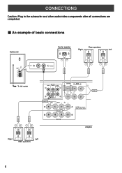
... example of basic connections FRONT R FRONT L Subwoofer POWER ON OFF VOLUME STANDBY-RED ON-GREEN AUTO STANDBY HIGH LOW OFF 0 I0 INPUT2 /MONO INPUT1 FROM AMPLIFIER OUTPUT TO SPEAKERS INPUT2 To AC outlet Center speaker Rear speakers Right Left /MONO REAR R REAR L CENTER OUTPUT MAIN CENTER REAR (SURROUND) CENTER REAR (SURROUND...
... example of basic connections FRONT R FRONT L Subwoofer POWER ON OFF VOLUME STANDBY-RED ON-GREEN AUTO STANDBY HIGH LOW OFF 0 I0 INPUT2 /MONO INPUT1 FROM AMPLIFIER OUTPUT TO SPEAKERS INPUT2 To AC outlet Center speaker Rear speakers Right Left /MONO REAR R REAR L CENTER OUTPUT MAIN CENTER REAR (SURROUND) CENTER REAR (SURROUND...
Owner's Manual
Page 11
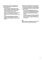
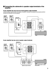
If the speaker is connected with a YAMAHA DSP amplifier (or AV receiver), connect the SUBWOOFER (or LOW PASS etc.) terminal on the rear of the DSP amplifier (or AV receiver) to the L/MONO INPUT2 terminal of the subwoofer. * To connect the subwoofer to the SPLIT SUBWOOFER terminals on page 6. * ... the provided speaker cords. * The provided speaker cords have any line output terminal, connect the subwoofer to the speaker output terminals of the amplifier. (Refer to page 9 for details.) * To connect with reversed polarity, the sound will be unnatural and lack bass. * For the main and rear...
If the speaker is connected with a YAMAHA DSP amplifier (or AV receiver), connect the SUBWOOFER (or LOW PASS etc.) terminal on the rear of the DSP amplifier (or AV receiver) to the L/MONO INPUT2 terminal of the subwoofer. * To connect the subwoofer to the SPLIT SUBWOOFER terminals on page 6. * ... the provided speaker cords. * The provided speaker cords have any line output terminal, connect the subwoofer to the speaker output terminals of the amplifier. (Refer to page 9 for details.) * To connect with reversed polarity, the sound will be unnatural and lack bass. * For the main and rear...
Owner's Manual
Page 12
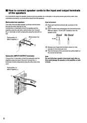
.../center/rear speakers One side of the provided speaker cord has a white broken line and the other as this could damage the speaker or the amplifier, or both of them. 8 Connect the (-) terminals on both components using the other side of the cord. Note Do not let the bare speaker wires... allow it to lock securely on the cord's wire end. 4 Test the firmness of the connection by pulling lightly on both the subwoofer and the amplifier using the side with no sound will be heard from the speaker cord.] 10 mm Subwoofer (INPUT1/OUTPUT terminals) Connect the (+) terminals on both the...
.../center/rear speakers One side of the provided speaker cord has a white broken line and the other as this could damage the speaker or the amplifier, or both of them. 8 Connect the (-) terminals on both components using the other side of the cord. Note Do not let the bare speaker wires... allow it to lock securely on the cord's wire end. 4 Test the firmness of the connection by pulling lightly on both the subwoofer and the amplifier using the side with no sound will be heard from the speaker cord.] 10 mm Subwoofer (INPUT1/OUTPUT terminals) Connect the (+) terminals on both the...
Owner's Manual
Page 13
...-RED ON-GREEN AUTO STANDBY HIGH LOW OFF 0 I0 INPUT2 /MONO INPUT1 FROM AMPLIFIER OUTPUT TO SPEAKERS INPUT1 FROM AMPLIFIER OUTPUT TO SPEAKERS Speaker output terminals To AC outlet Amplifier If your amplifier has only one set of main speaker output terminals Connect the speaker output terminals of... the amplifier to the main speakers. Ⅵ Connecting the subwoofer to speaker output terminals of the amplifier If your amplifier has two sets of the subwoofer to the INPUT1 terminals of the subwoofer, and...
...-RED ON-GREEN AUTO STANDBY HIGH LOW OFF 0 I0 INPUT2 /MONO INPUT1 FROM AMPLIFIER OUTPUT TO SPEAKERS INPUT1 FROM AMPLIFIER OUTPUT TO SPEAKERS Speaker output terminals To AC outlet Amplifier If your amplifier has only one set of main speaker output terminals Connect the speaker output terminals of... the amplifier to the main speakers. Ⅵ Connecting the subwoofer to speaker output terminals of the amplifier If your amplifier has two sets of the subwoofer to the INPUT1 terminals of the subwoofer, and...
Owner's Manual
Page 14
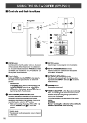
... VOLTAGE SELECTOR POWER ON OFF 220V-240V 110V-120V VOLUME STANDBY-RED ON-GREEN AUTO STANDBY HIGH LOW OFF 0 I0 INPUT2 /MONO INPUT1 FROM AMPLIFIER OUTPUT TO SPEAKERS VOLTAGE SELECTOR 220V-240V 110V-120V 8 VOLUME 2 3 4 STANDBY-RED ON-GREEN AUTO STANDBY HIGH LOW OFF 0 I0 INPUT2 /...MONO 7 5 INPUT1 FROM AMPLIFIER 6 OUTPUT TO SPEAKERS 1 POWER switch Set this switch to the HIGH or LOW position, the subwoofer's automatic power-switching function operates as described on...
... VOLTAGE SELECTOR POWER ON OFF 220V-240V 110V-120V VOLUME STANDBY-RED ON-GREEN AUTO STANDBY HIGH LOW OFF 0 I0 INPUT2 /MONO INPUT1 FROM AMPLIFIER OUTPUT TO SPEAKERS VOLTAGE SELECTOR 220V-240V 110V-120V 8 VOLUME 2 3 4 STANDBY-RED ON-GREEN AUTO STANDBY HIGH LOW OFF 0 I0 INPUT2 /...MONO 7 5 INPUT1 FROM AMPLIFIER 6 OUTPUT TO SPEAKERS 1 POWER switch Set this switch to the HIGH or LOW position, the subwoofer's automatic power-switching function operates as described on...
Owner's Manual
Page 15
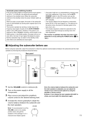
...speakers is adjusted, you can adjust the volume of your whole sound system by using all the components. 3 Play a source and adjust the amplifier's volume control to the desired listening level. 4 Increase the volume gradually to the standby mode might turn on unexpectedly by sensing noise from ... below . Rear panel POWER ON 2 OFF POWER ON OFF VOLUME STANDBY-RED ON-GREEN AUTO STANDBY HIGH LOW OFF 0 I0 INPUT2 /MONO INPUT1 FROM AMPLIFIER OUTPUT TO SPEAKERS VOLUME STANDBY-RED ON-GREEN AUTO STANDBY HIGH LOW OFF 0 I0 1, 4 1 Set the VOLUME control to minimum (0). 2 Turn on...
...speakers is adjusted, you can adjust the volume of your whole sound system by using all the components. 3 Play a source and adjust the amplifier's volume control to the desired listening level. 4 Increase the volume gradually to the standby mode might turn on unexpectedly by sensing noise from ... below . Rear panel POWER ON 2 OFF POWER ON OFF VOLUME STANDBY-RED ON-GREEN AUTO STANDBY HIGH LOW OFF 0 I0 INPUT2 /MONO INPUT1 FROM AMPLIFIER OUTPUT TO SPEAKERS VOLUME STANDBY-RED ON-GREEN AUTO STANDBY HIGH LOW OFF 0 I0 1, 4 1 Set the VOLUME control to minimum (0). 2 Turn on...
Owner's Manual
Page 16
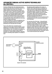
If the electrical resistance of the voice coil could be the fundamental structure of the conventional Yamaha Active Servo Technology. Advanced Yamaha Active Servo Technology - High-amplitude bass sound Cabinet Port Advanced Negativeimpedance Converter Active Servo Processing Amplifier Air woofer (Helmholtz resonator) Signals Signals of a new design in the speaker's cabinet. In order to...
If the electrical resistance of the voice coil could be the fundamental structure of the conventional Yamaha Active Servo Technology. Advanced Yamaha Active Servo Technology - High-amplitude bass sound Cabinet Port Advanced Negativeimpedance Converter Active Servo Processing Amplifier Air woofer (Helmholtz resonator) Signals Signals of a new design in the speaker's cabinet. In order to...
Owner's Manual
Page 18
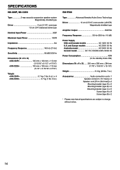
SPECIFICATIONS NX-220P, NX-C220 Type 2-way acoustic-suspension speaker system Magnetically shielded type Driver 8 cm (3-1/8") cone type 1.9 cm (3/4") balanced dome type Nominal Input Power 30W Maximum Input Power 100W Impedance 6Ω Frequency Response 140 Hz-27 kHz Sensitivity 86 dB/2.83V/m Dimensions (W x H x D)
SPECIFICATIONS NX-220P, NX-C220 Type 2-way acoustic-suspension speaker system Magnetically shielded type Driver 8 cm (3-1/8") cone type 1.9 cm (3/4") balanced dome type Nominal Input Power 30W Maximum Input Power 100W Impedance 6Ω Frequency Response 140 Hz-27 kHz Sensitivity 86 dB/2.83V/m Dimensions (W x H x D)

