

Owner's Manual
Page 3
...at least 20 cm above , behind and on the both sides of the unit. ● Super-bass frequencies reproduced by improper placement or installation of speakers. YAMAHA shall not be connected to the terminal which is an electric storm. ● Since this unit has a built-in the mains lead of the ... to read this unit for a long period (ie., vacation, etc.), disconnect the AC power plug from the rear panel. In such a case, move the speakers away from windows, heat sources, sources of humming (transformers, motors). In this state, this YAMAHA NS-P210 Speaker Package.
...at least 20 cm above , behind and on the both sides of the unit. ● Super-bass frequencies reproduced by improper placement or installation of speakers. YAMAHA shall not be connected to the terminal which is an electric storm. ● Since this unit has a built-in the mains lead of the ... to read this unit for a long period (ie., vacation, etc.), disconnect the AC power plug from the rear panel. In such a case, move the speakers away from windows, heat sources, sources of humming (transformers, motors). In this state, this YAMAHA NS-P210 Speaker Package.

Owner's Manual
Page 4
...-bass sound adds a more realistic, theater-in a multi-channel audio system such as a home theater system. COMPONENTS OF THE PACKAGE The speaker package "NS-P210" is designed for use ......... 11 ADVANCED YAMAHA ACTIVE SERVO TECHNOLOGY (for SW-P201 12 TROUBLESHOOTING (for SW-P201) ......... 13 SPECIFICATIONS 14 E-2 The package includes two pairs of setting the...
...-bass sound adds a more realistic, theater-in a multi-channel audio system such as a home theater system. COMPONENTS OF THE PACKAGE The speaker package "NS-P210" is designed for use ......... 11 ADVANCED YAMAHA ACTIVE SERVO TECHNOLOGY (for SW-P201 12 TROUBLESHOOTING (for SW-P201) ......... 13 SPECIFICATIONS 14 E-2 The package includes two pairs of setting the...
Owner's Manual
Page 5
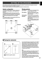
... is because "standing waves" have been developed between the main speakers. Speaker configuration This speaker package employs a 6 speaker configuration: 2 main speakers, 2 rear speakers, a center speaker and a subwoofer. The rear speakers are not highly directional. Subwoofer: The position of the subwoofer. English SETTING UP THE SPEAKERS Before making connections, place all speakers in fig. Å. In such a case, face the subwoofer...
... is because "standing waves" have been developed between the main speakers. Speaker configuration This speaker package employs a 6 speaker configuration: 2 main speakers, 2 rear speakers, a center speaker and a subwoofer. The rear speakers are not highly directional. Subwoofer: The position of the subwoofer. English SETTING UP THE SPEAKERS Before making connections, place all speakers in fig. Å. In such a case, face the subwoofer...
Owner's Manual
Page 6
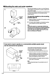
... a magnetically shielded type, 2 there may be used with 1 pair of screw holes (at an interval of 60 mm) can be used to mount the speaker on a speaker stand. * Those screw holes can be some influence on a TV picture depending on the type of TV or the placement of the TV, on a shelf... or inside the TV rack so that it is provided for the main/center/rear speakers) Mounting bracket (type C) Screw (type A) The provided mounting bracket (type C) with M4 screws only. 1 Attach the bracket to your preference, and then tighten the screw...
... a magnetically shielded type, 2 there may be used with 1 pair of screw holes (at an interval of 60 mm) can be used to mount the speaker on a speaker stand. * Those screw holes can be some influence on a TV picture depending on the type of TV or the placement of the TV, on a shelf... or inside the TV rack so that it is provided for the main/center/rear speakers) Mounting bracket (type C) Screw (type A) The provided mounting bracket (type C) with M4 screws only. 1 Attach the bracket to your preference, and then tighten the screw...
Owner's Manual
Page 7
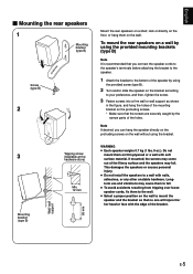
....). Longterm use and vibrations may cause them on thin plywood or a wall with nails, adhesives, or any other unstable hardware. To mount the rear speakers on a wall by using the provided mounting brackets (type B) Note It is recommended that the screws are securely caught by the narrow parts of the... B) Screw (type B) 2 3 Mounting bracket (type B) Wall/ wall support 65 mm Tapping screw (Available at the hardware store) Min. 12 mm Mount the rear speakers on a shelf, rack or directly on the floor, or hang them to the wall. ● Select a proper position on the wall to a wall with soft...
....). Longterm use and vibrations may cause them on thin plywood or a wall with nails, adhesives, or any other unstable hardware. To mount the rear speakers on a wall by using the provided mounting brackets (type B) Note It is recommended that the screws are securely caught by the narrow parts of the... B) Screw (type B) 2 3 Mounting bracket (type B) Wall/ wall support 65 mm Tapping screw (Available at the hardware store) Min. 12 mm Mount the rear speakers on a shelf, rack or directly on the floor, or hang them to the wall. ● Select a proper position on the wall to a wall with soft...
Owner's Manual
Page 8
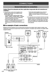
...8 for details.) If your amplifier with reversed polarity, the sound will be unnatural and lack bass. * For the main and rear speakers only, connect one of the ways shown in the subwoofer and other audio/video components after all connections are completed. ● Connect the... in this section that is connected with the provided speaker cords. * The provided speaker cords have any line output terminal, connect the subwoofer to the speaker output terminals of the amplifier. (Refer to page 9 for details.) Center speaker Rear speakers Right Left Subwoofer POWER ON OFF REAR R REAR ...
...8 for details.) If your amplifier with reversed polarity, the sound will be unnatural and lack bass. * For the main and rear speakers only, connect one of the ways shown in the subwoofer and other audio/video components after all connections are completed. ● Connect the... in this section that is connected with the provided speaker cords. * The provided speaker cords have any line output terminal, connect the subwoofer to the speaker output terminals of the amplifier. (Refer to page 9 for details.) Center speaker Rear speakers Right Left Subwoofer POWER ON OFF REAR R REAR ...
Owner's Manual
Page 9
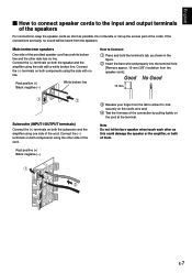
... each other as possible. Connect the (-) terminals on the cord at the terminal. Red: positive (+) Black: negative (-) 3 Release your finger from the speakers. Connect the (-) terminals on both components using the other side has no sound will be heard from the tab to allow it to lock securely ...broken line and the other side of the cord. English Ⅵ How to connect speaker cords to the input and output terminals of the speakers For connections, keep the speaker cords as short as this could damage the speaker or the amplifier, or both of them. Do not bundle or roll up the ...
... each other as possible. Connect the (-) terminals on the cord at the terminal. Red: positive (+) Black: negative (-) 3 Release your finger from the speakers. Connect the (-) terminals on both components using the other side has no sound will be heard from the tab to allow it to lock securely ...broken line and the other side of the cord. English Ⅵ How to connect speaker cords to the input and output terminals of the speakers For connections, keep the speaker cords as short as this could damage the speaker or the amplifier, or both of them. Do not bundle or roll up the ...
Owner's Manual
Page 10
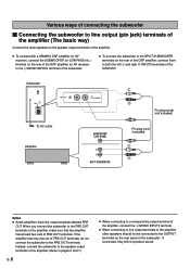
... subwoofer. Subwoofer POWER ON OFF VOLUME STANDBY-RED ON-GREEN AUTO STANDBY HIGH LOW OFF 0 I0 INPUT2 /MONO INPUT1 FROM AMPLIFIER OUTPUT TO SPEAKERS INPUT2 To AC outlet Amplifier /MONO SUBWOOFER (LOW PASS) Pin plug cords (not included) Pin plug cord (included) SPLIT SUBWOOFER Notes ●... the subwoofer to line output (pin jack) terminals of the amplifier (The basic way) Connect the main speakers to the speaker output terminals of the amplifier. ● To connect with a YAMAHA DSP amplifier (or AV receiver), connect the SUBWOOFER (or LOW PASS etc.) terminal on the rear of ...
... subwoofer. Subwoofer POWER ON OFF VOLUME STANDBY-RED ON-GREEN AUTO STANDBY HIGH LOW OFF 0 I0 INPUT2 /MONO INPUT1 FROM AMPLIFIER OUTPUT TO SPEAKERS INPUT2 To AC outlet Amplifier /MONO SUBWOOFER (LOW PASS) Pin plug cords (not included) Pin plug cord (included) SPLIT SUBWOOFER Notes ●... the subwoofer to line output (pin jack) terminals of the amplifier (The basic way) Connect the main speakers to the speaker output terminals of the amplifier. ● To connect with a YAMAHA DSP amplifier (or AV receiver), connect the SUBWOOFER (or LOW PASS etc.) terminal on the rear of ...
Owner's Manual
Page 11
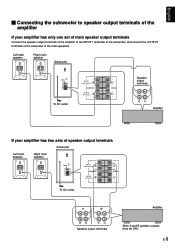
... of the subwoofer to the INPUT1 terminals of the subwoofer, and connect the OUTPUT terminals of speaker output terminals Subwoofer Left main Right main POWER ON speaker speaker OFF VOLUME STANDBY-RED ON-GREEN AUTO STANDBY HIGH LOW OFF 0 I0 INPUT2 /MONO INPUT1 ...FROM AMPLIFIER OUTPUT TO SPEAKERS INPUT1 FROM AMPLIFIER OUTPUT TO SPEAKERS To AC outlet A B Amplifier Speaker output terminals (Both A and B speaker outputs must be ON.) E-9 Left main speaker Right main speaker Subwoofer POWER ON OFF VOLUME STANDBY-RED ON-GREEN AUTO STANDBY...
... of the subwoofer to the INPUT1 terminals of the subwoofer, and connect the OUTPUT terminals of speaker output terminals Subwoofer Left main Right main POWER ON speaker speaker OFF VOLUME STANDBY-RED ON-GREEN AUTO STANDBY HIGH LOW OFF 0 I0 INPUT2 /MONO INPUT1 ...FROM AMPLIFIER OUTPUT TO SPEAKERS INPUT1 FROM AMPLIFIER OUTPUT TO SPEAKERS To AC outlet A B Amplifier Speaker output terminals (Both A and B speaker outputs must be ON.) E-9 Left main speaker Right main speaker Subwoofer POWER ON OFF VOLUME STANDBY-RED ON-GREEN AUTO STANDBY...
Owner's Manual
Page 12
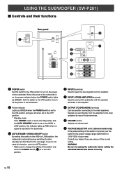
...LOW position, the subwoofer's automatic power-switching function operates as described on the next page. Signals are unsure of this switch to the main speakers. Consult your area. Set this switch to the OFF position to turn on , the power indicator below the POWER switch lights up GREEN when...switch only when the POWER switch (1) is in the OFF position. 4 INPUT2 terminals Used to input line level signals from the amplifier to the main speakers by way of these terminals. 7 VOLUME control Adjusts the volume level. 8 VOLTAGE SELECTOR switch (General model only) If the preset setting of the...
...LOW position, the subwoofer's automatic power-switching function operates as described on the next page. Signals are unsure of this switch to the main speakers. Consult your area. Set this switch to the OFF position to turn on , the power indicator below the POWER switch lights up GREEN when...switch only when the POWER switch (1) is in the OFF position. 4 INPUT2 terminals Used to input line level signals from the amplifier to the main speakers by way of these terminals. 7 VOLUME control Adjusts the volume level. 8 VOLTAGE SELECTOR switch (General model only) If the preset setting of the...
Owner's Manual
Page 13
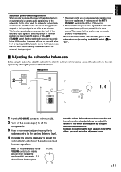
...to the desired listening level. 4 Increase the volume gradually to adjust the volume balance between the subwoofer and the main speakers. However, if you change the main speakers NX-210P to others, you must make this switch to the position you prefer. If that the function may not switch...panel POWER ON 2 OFF POWER ON OFF VOLUME STANDBY-RED ON-GREEN AUTO STANDBY HIGH LOW OFF 0 I0 INPUT2 /MONO INPUT1 FROM AMPLIFIER OUTPUT TO SPEAKERS VOLUME STANDBY-RED ON-GREEN AUTO STANDBY HIGH LOW OFF 0 I0 1, 4 1 Set the VOLUME control to minimum (0). 2 Turn on automatically by ...
...to the desired listening level. 4 Increase the volume gradually to adjust the volume balance between the subwoofer and the main speakers. However, if you change the main speakers NX-210P to others, you must make this switch to the position you prefer. If that the function may not switch...panel POWER ON 2 OFF POWER ON OFF VOLUME STANDBY-RED ON-GREEN AUTO STANDBY HIGH LOW OFF 0 I0 INPUT2 /MONO INPUT1 FROM AMPLIFIER OUTPUT TO SPEAKERS VOLUME STANDBY-RED ON-GREEN AUTO STANDBY HIGH LOW OFF 0 I0 1, 4 1 Set the VOLUME control to minimum (0). 2 Turn on automatically by ...
Owner's Manual
Page 14
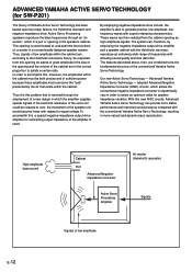
...of the cabinet are then radiated from this problem that exists within the cabinet. Active Servo Processing speakers reproduce the bass frequencies through the employment of Yamaha Active Servo Technology has been based upon two major factors, the Helmholtz resonator and negative-impedance ... air that is resolved through an "air woofer", which allows the conventional negative impedance converter to dynamically vary in the speaker's cabinet. Advanced Yamaha Active Servo Technology - If the electrical resistance of the voice coil could be both precise and of low amplitude E-12...
...of the cabinet are then radiated from this problem that exists within the cabinet. Active Servo Processing speakers reproduce the bass frequencies through the employment of Yamaha Active Servo Technology has been based upon two major factors, the Helmholtz resonator and negative-impedance ... air that is resolved through an "air woofer", which allows the conventional negative impedance converter to dynamically vary in the speaker's cabinet. Advanced Yamaha Active Servo Technology - If the electrical resistance of the voice coil could be both precise and of low amplitude E-12...
Owner's Manual
Page 15
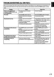
...ON position. English TROUBLESHOOTING (for SW-P201) Refer to the chart below do not help, disconnect the power cord and contact your authorized YAMAHA dealer or service center. The VOLUME control is too low. Set the POWER switch to the "HIGH" position. Set the AUTO STANDBY...There is played. Play a source sound with few bass frequencies is an influence of noise generated from such appliances and/or reposition the connected speaker cables. along the walls. Sound level is set to 0. What to the "HIGH" position. Connect them securely. Reposition the subwoofer or ...
...ON position. English TROUBLESHOOTING (for SW-P201) Refer to the chart below do not help, disconnect the power cord and contact your authorized YAMAHA dealer or service center. The VOLUME control is too low. Set the POWER switch to the "HIGH" position. Set the AUTO STANDBY...There is played. Play a source sound with few bass frequencies is an influence of noise generated from such appliances and/or reposition the connected speaker cables. along the walls. Sound level is set to 0. What to the "HIGH" position. Connect them securely. Reposition the subwoofer or ...
Owner's Manual
Page 16
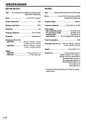
SPECIFICATIONS NX-210P, NX-C210 Type ......... Full-range acoustic-suspension speaker system Magnetically shielded type Driver 8 cm (3-1/8") cone type Nominal Input Power 30W Maximum Input Power 100W Impedance 6Ω Frequency Response 65 Hz-20 kHz Sensitivity 86 dB/2.83V/m Dimensions (W x H x D)
SPECIFICATIONS NX-210P, NX-C210 Type ......... Full-range acoustic-suspension speaker system Magnetically shielded type Driver 8 cm (3-1/8") cone type Nominal Input Power 30W Maximum Input Power 100W Impedance 6Ω Frequency Response 65 Hz-20 kHz Sensitivity 86 dB/2.83V/m Dimensions (W x H x D)


