

Owner's Manual
Page 3
... from this appliance, it in a safe place for future reference. ● Install the speakers in feedback. ● Any time you note distortion, reduce the volume control on the rear panel of this YAMAHA NS-P210 Speaker Package. Never allow a space of speakers. Extremely loud playing of humming (transformers, motors). Keep it should be destroyed, as a plug...
... from this appliance, it in a safe place for future reference. ● Install the speakers in feedback. ● Any time you note distortion, reduce the volume control on the rear panel of this YAMAHA NS-P210 Speaker Package. Never allow a space of speakers. Extremely loud playing of humming (transformers, motors). Keep it should be destroyed, as a plug...

Owner's Manual
Page 4
...a home theater system. COMPONENTS OF THE PACKAGE The speaker package "NS-P210" is designed for connections 6 An example of basic connections 6 How to connect speaker cords to the input and output terminals of the speakers 7 Various ways of connecting the subwoofer .... 8 ... Cover CAUTION 1 COMPONENTS OF THE PACKAGE 2 SETTING UP THE SPEAKERS 3 Placing the subwoofer 3 Mounting the main and center speakers .......... 4 Mounting the rear speakers 5 CONNECTIONS 6 General information for use ......... 11 ADVANCED YAMAHA ACTIVE SERVO TECHNOLOGY (for SW-P201 12 TROUBLESHOOTING (for SW-...
...a home theater system. COMPONENTS OF THE PACKAGE The speaker package "NS-P210" is designed for connections 6 An example of basic connections 6 How to connect speaker cords to the input and output terminals of the speakers 7 Various ways of connecting the subwoofer .... 8 ... Cover CAUTION 1 COMPONENTS OF THE PACKAGE 2 SETTING UP THE SPEAKERS 3 Placing the subwoofer 3 Mounting the main and center speakers .......... 4 Mounting the rear speakers 5 CONNECTIONS 6 General information for use ......... 11 ADVANCED YAMAHA ACTIVE SERVO TECHNOLOGY (for SW-P201 12 TROUBLESHOOTING (for SW-...
Owner's Manual
Page 5
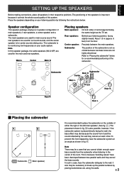
...the bass effect may be a case that you cannot obtain enough super- The positioning of the subwoofer. Speaker configuration This speaker package employs a 6 speaker configuration: 2 main speakers, 2 rear speakers, a center speaker and a subwoofer. Subwoofer: The position of the subwoofer is not so critical because low bass tones are... the whole sound quality of this from the subwoofer when listening in the center of either the right or the left main speaker. (See fig. Å .) The placement shown in their respective positions. Refer to break up the parallel surfaces by following...
...the bass effect may be a case that you cannot obtain enough super- The positioning of the subwoofer. Speaker configuration This speaker package employs a 6 speaker configuration: 2 main speakers, 2 rear speakers, a center speaker and a subwoofer. Subwoofer: The position of the subwoofer is not so critical because low bass tones are... the whole sound quality of this from the subwoofer when listening in the center of either the right or the left main speaker. (See fig. Å .) The placement shown in their respective positions. Refer to break up the parallel surfaces by following...
Owner's Manual
Page 6
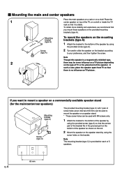
...C) with 1 pair of screw holes (at an interval of 60 mm) can be used with M4 screws only. 1 Attach the bracket to mount the speaker on a speaker stand. * Those screw holes can be some influence on a TV picture depending on TV picture. Note The mounting bracket (type C) is no influence on... the type of TV or the placement of 5 speakers. 60 mm E-4 To obtain more stability and usefulness, we recommend that it is a magnetically shielded type, 2 there may be used to the bottom of...
...C) with 1 pair of screw holes (at an interval of 60 mm) can be used with M4 screws only. 1 Attach the bracket to mount the speaker on a speaker stand. * Those screw holes can be some influence on a TV picture depending on TV picture. Note The mounting bracket (type C) is no influence on... the type of TV or the placement of 5 speakers. 60 mm E-4 To obtain more stability and usefulness, we recommend that it is a magnetically shielded type, 2 there may be used to the bottom of...
Owner's Manual
Page 7
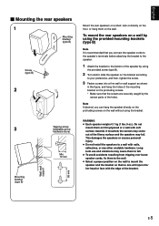
... on the protruding screws on the wall without using the provided screw (type B). 2 Turn and/or slide the speaker on the bracket according to your preference, and then, tighten the screw. 3 Fasten screws into a firm wall or wall support as shown in the figure... to fall . Longterm use and vibrations may come out of the holes. This damages the speakers or causes personal injury. ● Do not install the speakers to the bottom of the bracket. English Ⅵ Mounting the rear speakers 1 Mounting bracket (type B) Screw (type B) 2 3 Mounting bracket (type B) Wall/ wall support 65 mm Tapping...
... on the protruding screws on the wall without using the provided screw (type B). 2 Turn and/or slide the speaker on the bracket according to your preference, and then, tighten the screw. 3 Fasten screws into a firm wall or wall support as shown in the figure... to fall . Longterm use and vibrations may come out of the holes. This damages the speakers or causes personal injury. ● Do not install the speakers to the bottom of the bracket. English Ⅵ Mounting the rear speakers 1 Mounting bracket (type B) Screw (type B) 2 3 Mounting bracket (type B) Wall/ wall support 65 mm Tapping...
Owner's Manual
Page 8
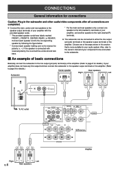
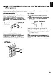
.... ● The subwoofer can be connected to either the line output (pin jack) terminals or the speaker output terminals of your component to page 9 for details.) Center speaker Rear speakers Right Left Subwoofer POWER ON OFF REAR R REAR L CENTER VOLUME STANDBY-RED ON-GREEN AUTO STANDBY HIGH... Plug in this section that is more suitable for your amplifier with the provided speaker cords. * The provided speaker cords have labels marked FRONT L, FRONT R, CENTER, REAR L or REAR R. If the speaker is connected with reversed polarity, the sound will be connected to the subwoofer. &#...
.... ● The subwoofer can be connected to either the line output (pin jack) terminals or the speaker output terminals of your component to page 9 for details.) Center speaker Rear speakers Right Left Subwoofer POWER ON OFF REAR R REAR L CENTER VOLUME STANDBY-RED ON-GREEN AUTO STANDBY HIGH... Plug in this section that is more suitable for your amplifier with the provided speaker cords. * The provided speaker cords have labels marked FRONT L, FRONT R, CENTER, REAR L or REAR R. If the speaker is connected with reversed polarity, the sound will be connected to the subwoofer. &#...
Owner's Manual
Page 9
... Black: negative (-) White broken line How to Connect: 1 Press and hold the terminal's tab, as possible. E-7 English Ⅵ How to connect speaker cords to the input and output terminals of the connection by pulling lightly on the cord at the terminal. Connect the (-) terminals on both components... using one side of the cord. Connect the (-) terminals on the cord's wire end. 4 Test the firmness of the speakers For connections, keep the speaker cords as short as shown in the figure. 2 Insert the bare wire end properly into the terminal hole. [Remove approx. 10...
... Black: negative (-) White broken line How to Connect: 1 Press and hold the terminal's tab, as possible. E-7 English Ⅵ How to connect speaker cords to the input and output terminals of the connection by pulling lightly on the cord at the terminal. Connect the (-) terminals on both components... using one side of the cord. Connect the (-) terminals on the cord's wire end. 4 Test the firmness of the speakers For connections, keep the speaker cords as short as shown in the figure. 2 Insert the bare wire end properly into the terminal hole. [Remove approx. 10...
Owner's Manual
Page 10
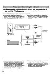
... OUT terminals of the amplifier, make sure that the amplifier has at least two sets of PRE OUT terminals. Instead, connect the subwoofer to the speaker output terminals of the amplifier. (Refer to pages 6 and 7.) E-8 ● When connecting to a monaural line output terminal of the amplifier, ...Connecting the subwoofer to line output (pin jack) terminals of the amplifier (The basic way) Connect the main speakers to the speaker output terminals of the amplifier. ● To connect with a YAMAHA DSP amplifier (or AV receiver), connect the SUBWOOFER (or LOW PASS etc.) terminal on the rear of the...
... OUT terminals of the amplifier, make sure that the amplifier has at least two sets of PRE OUT terminals. Instead, connect the subwoofer to the speaker output terminals of the amplifier. (Refer to pages 6 and 7.) E-8 ● When connecting to a monaural line output terminal of the amplifier, ...Connecting the subwoofer to line output (pin jack) terminals of the amplifier (The basic way) Connect the main speakers to the speaker output terminals of the amplifier. ● To connect with a YAMAHA DSP amplifier (or AV receiver), connect the SUBWOOFER (or LOW PASS etc.) terminal on the rear of the...
Owner's Manual
Page 11
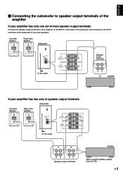
...0 I0 INPUT2 /MONO INPUT1 FROM AMPLIFIER OUTPUT TO SPEAKERS INPUT1 FROM AMPLIFIER OUTPUT TO SPEAKERS Speaker output terminals To AC outlet Amplifier If your amplifier has only one set of main speaker output terminals Connect the speaker output terminals of the amplifier to the INPUT1 terminals of...the subwoofer, and connect the OUTPUT terminals of the subwoofer to speaker output terminals of the amplifier If your amplifier has two sets of speaker output terminals Subwoofer Left main Right main POWER ON speaker speaker OFF VOLUME STANDBY-RED ON-GREEN AUTO STANDBY HIGH LOW OFF...
...0 I0 INPUT2 /MONO INPUT1 FROM AMPLIFIER OUTPUT TO SPEAKERS INPUT1 FROM AMPLIFIER OUTPUT TO SPEAKERS Speaker output terminals To AC outlet Amplifier If your amplifier has only one set of main speaker output terminals Connect the speaker output terminals of the amplifier to the INPUT1 terminals of...the subwoofer, and connect the OUTPUT terminals of the subwoofer to speaker output terminals of the amplifier If your amplifier has two sets of speaker output terminals Subwoofer Left main Right main POWER ON speaker speaker OFF VOLUME STANDBY-RED ON-GREEN AUTO STANDBY HIGH LOW OFF...
Owner's Manual
Page 12
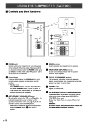
... POWER ON OFF 220V-240V 110V-120V VOLUME STANDBY-RED ON-GREEN AUTO STANDBY HIGH LOW OFF 0 I0 INPUT2 /MONO INPUT1 FROM AMPLIFIER OUTPUT TO SPEAKERS VOLTAGE SELECTOR 220V-240V 110V-120V 8 VOLUME 2 3 4 STANDBY-RED ON-GREEN AUTO STANDBY HIGH LOW OFF 0 I0 INPUT2 /MONO 7 5 INPUT1 FROM AMPLIFIER... only when the POWER switch (1) is in the OFF position. 4 INPUT2 terminals Used to input line level signals from the amplifier to the main speakers by way of these terminals. 7 VOLUME control Adjusts the volume level. 8 VOLTAGE SELECTOR switch (General model only) If the preset setting of the...
... POWER ON OFF 220V-240V 110V-120V VOLUME STANDBY-RED ON-GREEN AUTO STANDBY HIGH LOW OFF 0 I0 INPUT2 /MONO INPUT1 FROM AMPLIFIER OUTPUT TO SPEAKERS VOLTAGE SELECTOR 220V-240V 110V-120V 8 VOLUME 2 3 4 STANDBY-RED ON-GREEN AUTO STANDBY HIGH LOW OFF 0 I0 INPUT2 /MONO 7 5 INPUT1 FROM AMPLIFIER... only when the POWER switch (1) is in the OFF position. 4 INPUT2 terminals Used to input line level signals from the amplifier to the main speakers by way of these terminals. 7 VOLUME control Adjusts the volume level. 8 VOLTAGE SELECTOR switch (General model only) If the preset setting of the...
Owner's Manual
Page 13
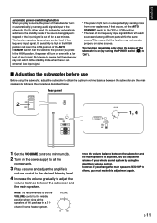
... for a few minutes. But please be aware that occurs, set the VOLUME control to adjust the volume balance between the subwoofer and the main speakers is adjusted, you can adjust the volume of input signal. On the other appliances. In the HIGH position, the power will turn on automatically ... panel POWER ON 2 OFF POWER ON OFF VOLUME STANDBY-RED ON-GREEN AUTO STANDBY HIGH LOW OFF 0 I0 INPUT2 /MONO INPUT1 FROM AMPLIFIER OUTPUT TO SPEAKERS VOLUME STANDBY-RED ON-GREEN AUTO STANDBY HIGH LOW OFF 0 I0 1, 4 1 Set the VOLUME control to the subwoofer. Note: It is recommended to ...
... for a few minutes. But please be aware that occurs, set the VOLUME control to adjust the volume balance between the subwoofer and the main speakers is adjusted, you can adjust the volume of input signal. On the other appliances. In the HIGH position, the power will turn on automatically ... panel POWER ON 2 OFF POWER ON OFF VOLUME STANDBY-RED ON-GREEN AUTO STANDBY HIGH LOW OFF 0 I0 INPUT2 /MONO INPUT1 FROM AMPLIFIER OUTPUT TO SPEAKERS VOLUME STANDBY-RED ON-GREEN AUTO STANDBY HIGH LOW OFF 0 I0 1, 4 1 Set the VOLUME control to the subwoofer. Note: It is recommended to ...
Owner's Manual
Page 14
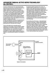
...be the fundamental structure of frequencies with respect to generate precise, low-amplitude, lowfrequency waves with the conventional Yamaha Active Servo Technology, resulting in the speaker's cabinet. Thus it is this opening as high-amplitude signals. High-amplitude bass sound Cabinet Port Advanced... to be outputted from the cabinet opening is able to signal voltage. Our new Active Servo Technology - ADVANCED YAMAHA ACTIVE SERVO TECHNOLOGY (for speaker impedance variation. In order to satisfy a certain ratio. If the electrical resistance of the voice coil could be...
...be the fundamental structure of frequencies with respect to generate precise, low-amplitude, lowfrequency waves with the conventional Yamaha Active Servo Technology, resulting in the speaker's cabinet. Thus it is this opening as high-amplitude signals. High-amplitude bass sound Cabinet Port Advanced... to be outputted from the cabinet opening is able to signal voltage. Our new Active Servo Technology - ADVANCED YAMAHA ACTIVE SERVO TECHNOLOGY (for speaker impedance variation. In order to satisfy a certain ratio. If the electrical resistance of the voice coil could be...
Owner's Manual
Page 15
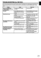
...Sound level is too low. The subwoofer turns into the standby mode unexpectedly. Speaker cords are not connected securely. The level of noise generated from such appliances and/or reposition the connected speaker cables. There is set the AUTO STANDBY switch to the chart below do ...not help, disconnect the power cord and contact your authorized YAMAHA dealer or service center. Connect them securely. Reposition the subwoofer ...
...Sound level is too low. The subwoofer turns into the standby mode unexpectedly. Speaker cords are not connected securely. The level of noise generated from such appliances and/or reposition the connected speaker cables. There is set the AUTO STANDBY switch to the chart below do ...not help, disconnect the power cord and contact your authorized YAMAHA dealer or service center. Connect them securely. Reposition the subwoofer ...
Owner's Manual
Page 16
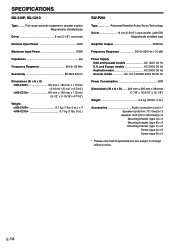
SPECIFICATIONS NX-210P, NX-C210 Type ......... Full-range acoustic-suspension speaker system Magnetically shielded type Driver 8 cm (3-1/8") cone type Nominal Input Power 30W Maximum Input Power 100W Impedance 6Ω Frequency Response 65 Hz-20 kHz Sensitivity 86 dB/2.83V/m Dimensions (W x H x D)
SPECIFICATIONS NX-210P, NX-C210 Type ......... Full-range acoustic-suspension speaker system Magnetically shielded type Driver 8 cm (3-1/8") cone type Nominal Input Power 30W Maximum Input Power 100W Impedance 6Ω Frequency Response 65 Hz-20 kHz Sensitivity 86 dB/2.83V/m Dimensions (W x H x D)


