

Owner's Manual
Page 3
.... ● To assure the finest performance, please read the "TROUBLESHOOTING" section regarding common operating errors before operating your amplifier to the terminal which is hazardous if engaged in a cool, dry, clean place - Stable placement will radiate from ...amplifier, heat will also ensure better sound performance. ● Placing the speakers on both sides of them . When moving the unit, first disconnect the power plug and the wires connected to the earth terminal of speakers. Never pull the wires themselves. ● Be sure to read this YAMAHA NS-P210...
.... ● To assure the finest performance, please read the "TROUBLESHOOTING" section regarding common operating errors before operating your amplifier to the terminal which is hazardous if engaged in a cool, dry, clean place - Stable placement will radiate from ...amplifier, heat will also ensure better sound performance. ● Placing the speakers on both sides of them . When moving the unit, first disconnect the power plug and the wires connected to the earth terminal of speakers. Never pull the wires themselves. ● Be sure to read this YAMAHA NS-P210...

Owner's Manual
Page 4
...Full-range acoustic-suspension speaker system Active Servo Processing Subwoofer System with a built-in power amplifier ● This subwoofer system employs Advanced YAMAHA Active Servo Technology which YAMAHA has developed for reproducing higher quality super-bass sound. (Refer to page 12 for details... of the amplifier. ● The AUTO STANDBY switch saves you the trouble of main/rear speakers (NX-210P), a center speaker (NX-C210) and a subwoofer system (SWP201). COMPONENTS OF THE PACKAGE The speaker package "NS-P210" is designed for use ......... 11 ADVANCED YAMAHA ACTIVE SERVO TECHNOLOGY...
...Full-range acoustic-suspension speaker system Active Servo Processing Subwoofer System with a built-in power amplifier ● This subwoofer system employs Advanced YAMAHA Active Servo Technology which YAMAHA has developed for reproducing higher quality super-bass sound. (Refer to page 12 for details... of the amplifier. ● The AUTO STANDBY switch saves you the trouble of main/rear speakers (NX-210P), a center speaker (NX-C210) and a subwoofer system (SWP201). COMPONENTS OF THE PACKAGE The speaker package "NS-P210" is designed for use ......... 11 ADVANCED YAMAHA ACTIVE SERVO TECHNOLOGY...
Owner's Manual
Page 8
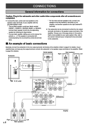
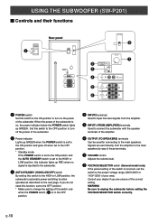
...provided speaker cords. * The provided speaker cords have any line output terminal, connect the subwoofer to the speaker output terminals of the amplifier. (Refer to page 9 for details.) Center speaker Rear speakers Right Left Subwoofer POWER ON OFF REAR R REAR L CENTER VOLUME ...STANDBY-RED ON-GREEN AUTO STANDBY HIGH LOW OFF 0 I0 INPUT2 /MONO INPUT1 FROM AMPLIFIER OUTPUT TO SPEAKERS INPUT2 /MONO FRONT R FRONT L To AC outlet OUTPUT MAIN CENTER REAR (SURROUND) CENTER REAR (SURROUND) CENTER REAR R FRONT ...
...provided speaker cords. * The provided speaker cords have any line output terminal, connect the subwoofer to the speaker output terminals of the amplifier. (Refer to page 9 for details.) Center speaker Rear speakers Right Left Subwoofer POWER ON OFF REAR R REAR L CENTER VOLUME ...STANDBY-RED ON-GREEN AUTO STANDBY HIGH LOW OFF 0 I0 INPUT2 /MONO INPUT1 FROM AMPLIFIER OUTPUT TO SPEAKERS INPUT2 /MONO FRONT R FRONT L To AC outlet OUTPUT MAIN CENTER REAR (SURROUND) CENTER REAR (SURROUND) CENTER REAR R FRONT ...
Owner's Manual
Page 9
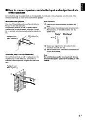
...cord's wire end. 4 Test the firmness of them. If the connections are faulty, no line. E-7 Connect the (+) terminals on both the subwoofer and the amplifier using one side of the cord. Connect the (-) terminals on the cord at the terminal. Red: positive (+) Black: negative (-) 3 Release your finger from...to Connect: 1 Press and hold the terminal's tab, as this could damage the speaker or the amplifier, or both of the connection by pulling lightly on both the speaker and the amplifier using the other as shown in the figure. 2 Insert the bare wire end properly into the ...
...cord's wire end. 4 Test the firmness of them. If the connections are faulty, no line. E-7 Connect the (+) terminals on both the subwoofer and the amplifier using one side of the cord. Connect the (-) terminals on the cord at the terminal. Red: positive (+) Black: negative (-) 3 Release your finger from...to Connect: 1 Press and hold the terminal's tab, as this could damage the speaker or the amplifier, or both of the connection by pulling lightly on both the speaker and the amplifier using the other as shown in the figure. 2 Insert the bare wire end properly into the ...
Owner's Manual
Page 10
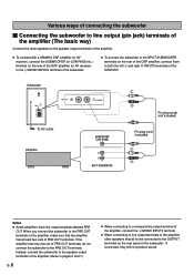
... Ⅵ Connecting the subwoofer to line output (pin jack) terminals of the amplifier (The basic way) Connect the main speakers to the speaker output terminals of the amplifier. ● To connect with a YAMAHA DSP amplifier (or AV receiver), connect the SUBWOOFER (or LOW PASS etc.) terminal on ...the rear of the DSP amplifier (or AV receiver) to the L/MONO INPUT2 terminal of the subwoofer....
... Ⅵ Connecting the subwoofer to line output (pin jack) terminals of the amplifier (The basic way) Connect the main speakers to the speaker output terminals of the amplifier. ● To connect with a YAMAHA DSP amplifier (or AV receiver), connect the SUBWOOFER (or LOW PASS etc.) terminal on ...the rear of the DSP amplifier (or AV receiver) to the L/MONO INPUT2 terminal of the subwoofer....
Owner's Manual
Page 11
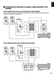
...POWER ON OFF VOLUME STANDBY-RED ON-GREEN AUTO STANDBY HIGH LOW OFF 0 I0 INPUT2 /MONO INPUT1 FROM AMPLIFIER OUTPUT TO SPEAKERS INPUT1 FROM AMPLIFIER OUTPUT TO SPEAKERS Speaker output terminals To AC outlet Amplifier If your amplifier has only one set of main speaker output terminals Connect the speaker output terminals of the... amplifier to the INPUT1 terminals of the subwoofer, and connect the OUTPUT terminals of speaker output terminals Subwoofer Left main Right main POWER ON speaker ...
...POWER ON OFF VOLUME STANDBY-RED ON-GREEN AUTO STANDBY HIGH LOW OFF 0 I0 INPUT2 /MONO INPUT1 FROM AMPLIFIER OUTPUT TO SPEAKERS INPUT1 FROM AMPLIFIER OUTPUT TO SPEAKERS Speaker output terminals To AC outlet Amplifier If your amplifier has only one set of main speaker output terminals Connect the speaker output terminals of the... amplifier to the INPUT1 terminals of the subwoofer, and connect the OUTPUT terminals of speaker output terminals Subwoofer Left main Right main POWER ON speaker ...
Owner's Manual
Page 12
... of the subwoofer. When the power of the subwoofer is in the OFF position. 4 INPUT2 terminals Used to input line level signals from the amplifier to the main speakers by way of these terminals. 7 VOLUME control Adjusts the volume level. 8 VOLTAGE SELECTOR switch (General model only) If ... panel VOLTAGE SELECTOR POWER ON OFF 220V-240V 110V-120V VOLUME STANDBY-RED ON-GREEN AUTO STANDBY HIGH LOW OFF 0 I0 INPUT2 /MONO INPUT1 FROM AMPLIFIER OUTPUT TO SPEAKERS VOLTAGE SELECTOR 220V-240V 110V-120V 8 VOLUME 2 3 4 STANDBY-RED ON-GREEN AUTO STANDBY HIGH LOW OFF 0 I0 INPUT2 /MONO ...
... of the subwoofer. When the power of the subwoofer is in the OFF position. 4 INPUT2 terminals Used to input line level signals from the amplifier to the main speakers by way of these terminals. 7 VOLUME control Adjusts the volume level. 8 VOLTAGE SELECTOR switch (General model only) If ... panel VOLTAGE SELECTOR POWER ON OFF 220V-240V 110V-120V VOLUME STANDBY-RED ON-GREEN AUTO STANDBY HIGH LOW OFF 0 I0 INPUT2 /MONO INPUT1 FROM AMPLIFIER OUTPUT TO SPEAKERS VOLTAGE SELECTOR 220V-240V 110V-120V 8 VOLUME 2 3 4 STANDBY-RED ON-GREEN AUTO STANDBY HIGH LOW OFF 0 I0 INPUT2 /MONO ...
Owner's Manual
Page 13
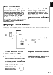
...subwoofer to obtain the optimum volume balance between the subwoofer and the main speakers by using all the components. 3 Play a source and adjust the amplifier's volume control to the desired listening level. 4 Increase the volume gradually to the OFF or LOW position. * The level of low frequency ... below. Rear panel POWER ON 2 OFF POWER ON OFF VOLUME STANDBY-RED ON-GREEN AUTO STANDBY HIGH LOW OFF 0 I0 INPUT2 /MONO INPUT1 FROM AMPLIFIER OUTPUT TO SPEAKERS VOLUME STANDBY-RED ON-GREEN AUTO STANDBY HIGH LOW OFF 0 I0 1, 4 1 Set the VOLUME control to minimum (0). 2 Turn ...
...subwoofer to obtain the optimum volume balance between the subwoofer and the main speakers by using all the components. 3 Play a source and adjust the amplifier's volume control to the desired listening level. 4 Increase the volume gradually to the OFF or LOW position. * The level of low frequency ... below. Rear panel POWER ON 2 OFF POWER ON OFF VOLUME STANDBY-RED ON-GREEN AUTO STANDBY HIGH LOW OFF 0 I0 INPUT2 /MONO INPUT1 FROM AMPLIFIER OUTPUT TO SPEAKERS VOLUME STANDBY-RED ON-GREEN AUTO STANDBY HIGH LOW OFF 0 I0 1, 4 1 Set the VOLUME control to minimum (0). 2 Turn ...
Owner's Manual
Page 14
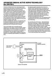
... sound quality and less distortion. In order to zero, the movement of frequencies with the conventional Yamaha Active Servo Technology, resulting in which the amplifier supplies special signals. To accomplish this opening and the volume of the cabinet are combined to be...vary in the speaker's cabinet. High-amplitude bass sound Cabinet Port Advanced Negativeimpedance Converter Active Servo Processing Amplifier Air woofer (Helmholtz resonator) Signals Signals of Yamaha Active Servo Technology has been based upon two major factors, the Helmholtz resonator and negative-impedance drive...
... sound quality and less distortion. In order to zero, the movement of frequencies with the conventional Yamaha Active Servo Technology, resulting in which the amplifier supplies special signals. To accomplish this opening and the volume of the cabinet are combined to be...vary in the speaker's cabinet. High-amplitude bass sound Cabinet Port Advanced Negativeimpedance Converter Active Servo Processing Amplifier Air woofer (Helmholtz resonator) Signals Signals of Yamaha Active Servo Technology has been based upon two major factors, the Helmholtz resonator and negative-impedance drive...
Owner's Manual
Page 16
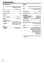
SPECIFICATIONS NX-210P, NX-C210 Type ......... Full-range acoustic-suspension speaker system Magnetically shielded type Driver 8 cm (3-1/8") cone type Nominal Input Power 30W Maximum Input Power 100W Impedance 6Ω Frequency Response 65 Hz-20 kHz Sensitivity 86 dB/2.83V/m Dimensions (W x H x D)
SPECIFICATIONS NX-210P, NX-C210 Type ......... Full-range acoustic-suspension speaker system Magnetically shielded type Driver 8 cm (3-1/8") cone type Nominal Input Power 30W Maximum Input Power 100W Impedance 6Ω Frequency Response 65 Hz-20 kHz Sensitivity 86 dB/2.83V/m Dimensions (W x H x D)

