Owners Manual
Page 3
...INFORMATION STATEMENT (DECLARATION OF CONFORMITY PROCEDURE) Responsible Party : Yamaha Corporation of America Address : 6600 Orangethorpe Ave., Buena Park, Calif. 90620 Telephone : 714-522-9011 Type of Equipment : Digital Mixing Studio Model Name : n8/n12 This device complies with FCC regulations does not guarantee ... or rear of this device must accept any interference received including interference that is subject to distribute this manual, meets FCC requirements. Utilize power outlets that interference will not result in harmful interference with these corrective measures...
...INFORMATION STATEMENT (DECLARATION OF CONFORMITY PROCEDURE) Responsible Party : Yamaha Corporation of America Address : 6600 Orangethorpe Ave., Buena Park, Calif. 90620 Telephone : 714-522-9011 Type of Equipment : Digital Mixing Studio Model Name : n8/n12 This device complies with FCC regulations does not guarantee ... or rear of this device must accept any interference received including interference that is subject to distribute this manual, meets FCC requirements. Utilize power outlets that interference will not result in harmful interference with these corrective measures...
Owners Manual
Page 4
... plate of the device. • Use only the included AC power adaptor (*PA-30 for the n12, PA-20 for the n8 or an equivalent recommended by qualified Yamaha service personnel. Connections • Before connecting the device to other electric devices. Depending on it containing ... or wrap the AC power adaptor with wet hands. The device contains no user-serviceable parts. Pulling by qualified Yamaha service personnel. • If this manual in a safe place for future reference. PRECAUTIONS PLEASE READ CAREFULLY BEFORE PROCEEDING * Please keep this device or the AC power...
... plate of the device. • Use only the included AC power adaptor (*PA-30 for the n12, PA-20 for the n8 or an equivalent recommended by qualified Yamaha service personnel. Connections • Before connecting the device to other electric devices. Depending on it containing ... or wrap the AC power adaptor with wet hands. The device contains no user-serviceable parts. Pulling by qualified Yamaha service personnel. • If this manual in a safe place for future reference. PRECAUTIONS PLEASE READ CAREFULLY BEFORE PROCEEDING * Please keep this device or the AC power...
Owners Manual
Page 5
... and unplug the power cord from the AC outlet. The performance of components with respect to which Yamaha owns copyrights or with moving contacts, such as shown in this owner's manual are for the same reason. • Do not insert your weight on the device or place ...is strictly prohibited except for a long time, make sure you unplug the power cord from those on your instrument. Consult qualifi ed Yamaha service personnel about replacing defective components. Such copyrighted materials include, without limitation, all computer software, music data, etc. Any unauthorized use of ...
... and unplug the power cord from the AC outlet. The performance of components with respect to which Yamaha owns copyrights or with moving contacts, such as shown in this owner's manual are for the same reason. • Do not insert your weight on the device or place ...is strictly prohibited except for a long time, make sure you unplug the power cord from those on your instrument. Consult qualifi ed Yamaha service personnel about replacing defective components. Such copyrighted materials include, without limitation, all computer software, music data, etc. Any unauthorized use of ...
Owners Manual
Page 6
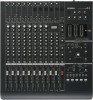
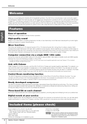
...Yamaha n8/n12 Digital Mixing Studio. The n8/n12 is a comprehensive music production system that adopts Sweet Spot Morphing technology. Please read the software license agreement before you start using an IEEE 1394 cable to suit your particular area. Also, keep this Owner's Manual before you to the n8/n12 using the n8/n12... such as Cubase 4. For example, you can be included depending on the n8/n12. Digital reverb at the end of operation Analog-like mixing interface ensures intuitive operation. The included Cubase AI 4 does not support surround. Features...
...Yamaha n8/n12 Digital Mixing Studio. The n8/n12 is a comprehensive music production system that adopts Sweet Spot Morphing technology. Please read the software license agreement before you start using an IEEE 1394 cable to suit your particular area. Also, keep this Owner's Manual before you to the n8/n12 using the n8/n12... such as Cubase 4. For example, you can be included depending on the n8/n12. Digital reverb at the end of operation Analog-like mixing interface ensures intuitive operation. The included Cubase AI 4 does not support surround. Features...
Owners Manual
Page 7
...n12 and DAW 207 Dimensional Diagrams 209 Block Diagram 210 MIDI Implementation Chart 211 Owner's Manual 7 Level and Decibel 9 Balanced or Unbalanced 9 How balanced lines work 9 How unbalanced lines work 10 Connector Variations 10 Phone connectors 10 RCA pin connectors 10 Inside Your Mixer 11 Basic Structure 11 Monitor mix... Mastery of EQ 29 Panning and balancing 30 Mixing into stereo 30 Applying reverb 31 Soloing a channel 32 Using the n8/n12 with Cubase 4/ Cubase Studio 4/Cubase AI 4 ........ 33 What you can do using the n8/n12 with Cubase ... 33 Computer setup for the ...
...n12 and DAW 207 Dimensional Diagrams 209 Block Diagram 210 MIDI Implementation Chart 211 Owner's Manual 7 Level and Decibel 9 Balanced or Unbalanced 9 How balanced lines work 9 How unbalanced lines work 10 Connector Variations 10 Phone connectors 10 RCA pin connectors 10 Inside Your Mixer 11 Basic Structure 11 Monitor mix... Mastery of EQ 29 Panning and balancing 30 Mixing into stereo 30 Applying reverb 31 Soloing a channel 32 Using the n8/n12 with Cubase 4/ Cubase Studio 4/Cubase AI 4 ........ 33 What you can do using the n8/n12 with Cubase ... 33 Computer setup for the ...
Owners Manual
Page 8
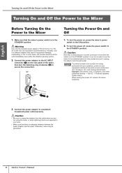
...On and Off 1. Warning Use only the included power adaptor (*PA-30 for the n12, PA20 for an extended period of current continues to use the mixer for the n8 or an equivalent recommended by Yamaha). If you are not using the mixer, or when lightning storms are expected in ...equipment damage, overheating, or fire. In such cases, the product warranty will be generated. 8 Owner's Manual NOTE To prevent sudden loud sounds from being produced ...
...On and Off 1. Warning Use only the included power adaptor (*PA-30 for the n12, PA20 for an extended period of current continues to use the mixer for the n8 or an equivalent recommended by Yamaha). If you are not using the mixer, or when lightning storms are expected in ...equipment damage, overheating, or fire. In such cases, the product warranty will be generated. 8 Owner's Manual NOTE To prevent sudden loud sounds from being produced ...
Owners Manual
Page 9
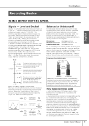
... or a power amplifier, features line inputs and outputs with a nominal level of one hot (and cold conductor) wrapped in the line. Owner's Manual 9 So, we use too many digits to transfer signals between the softest and loudest sounds detectable by random electromagnetic radiation (noise), such as radio and TV signals as well...
... or a power amplifier, features line inputs and outputs with a nominal level of one hot (and cold conductor) wrapped in the line. Owner's Manual 9 So, we use too many digits to transfer signals between the softest and loudest sounds detectable by random electromagnetic radiation (noise), such as radio and TV signals as well...
Owners Manual
Page 10
... convert unbalanced signals into balanced signals. Questions you pull the cable, it will input. and "What is used for the right audio channel. 10 Owner's Manual The plug features a lock mechanism, so even if you are less expensive than balanced cables. XLR-type connectors transmitter cable receiver How unbalanced lines work...
... convert unbalanced signals into balanced signals. Questions you pull the cable, it will input. and "What is used for the right audio channel. 10 Owner's Manual The plug features a lock mechanism, so even if you are less expensive than balanced cables. XLR-type connectors transmitter cable receiver How unbalanced lines work...

Owners Manual
Page 11
... send, etc. If the input signal is to collect signals from all channels and mix to achieve a good balance. Simplified mixer block diagram input channel master bus...stage enables you to process the input signal. It is too high for which the input signal flows. The n8/n12 features the following buses: • STEREO bus (L/R) • AUX bus (L/R) • REC bus (L/R) &#...master section enables you to adjust the level of the mixer's main output from buses. Owner's Manual 11 Here is a greatly simplified block diagram of configuring an audio system around a mixer is...
... send, etc. If the input signal is to collect signals from all channels and mix to achieve a good balance. Simplified mixer block diagram input channel master bus...stage enables you to process the input signal. It is too high for which the input signal flows. The n8/n12 features the following buses: • STEREO bus (L/R) • AUX bus (L/R) • REC bus (L/R) &#...master section enables you to adjust the level of the mixer's main output from buses. Owner's Manual 11 Here is a greatly simplified block diagram of configuring an audio system around a mixer is...
Owners Manual
Page 12
...effect unit. It then resumes its normal path. English STEREO BUS AUX BUS STEREO BUS REVERB BUS Recording Basics Monitor mix for musicians, external effects One important mixer function is to send out signals for signal processing via an external effect... to an appropriate level via the insert in digital reverb The n8/n12 features a REVERB bus that can adjust the level of the input channel signal and the amount of the main mix. On the n8/n12, a pre-fader signal is affected by the...The signal will change. effect unit INSERT OUT INPUT CHANNEL INSERT IN channel fader 12 Owner's Manual
...effect unit. It then resumes its normal path. English STEREO BUS AUX BUS STEREO BUS REVERB BUS Recording Basics Monitor mix for musicians, external effects One important mixer function is to send out signals for signal processing via an external effect... to an appropriate level via the insert in digital reverb The n8/n12 features a REVERB bus that can adjust the level of the input channel signal and the amount of the main mix. On the n8/n12, a pre-fader signal is affected by the...The signal will change. effect unit INSERT OUT INPUT CHANNEL INSERT IN channel fader 12 Owner's Manual
Owners Manual
Page 13
... 4 PHANTOM [+48V] switch This switch toggles phantom power for condenser microphones on and off for four channels simultaneously. (Channels 1-4 and channels 5-8 on the n12, and channels 1-4 on the n8). If you connect a microphone or other line-level instruments. 3 switch (high pass filter) This switch toggles the high... is turned on, phantom power DC +48V will be supplied to Pin 2 and Pin 3 of the corresponding XLR-type INPUT A jacks. % n12 Owner's Manual 13 Turn the switch off ( ) when you are connecting condenser microphones to the XLR-type INPUT A jacks on the rear panel, turn the ...
... 4 PHANTOM [+48V] switch This switch toggles phantom power for condenser microphones on and off for four channels simultaneously. (Channels 1-4 and channels 5-8 on the n12, and channels 1-4 on the n8). If you connect a microphone or other line-level instruments. 3 switch (high pass filter) This switch toggles the high... is turned on, phantom power DC +48V will be supplied to Pin 2 and Pin 3 of the corresponding XLR-type INPUT A jacks. % n12 Owner's Manual 13 Turn the switch off ( ) when you are connecting condenser microphones to the XLR-type INPUT A jacks on the rear panel, turn the ...
Owners Manual
Page 14
... right stereo channels. Yamaha also recommends that the... use the compressor, please refer to page 28. 14 Owner's Manual 9 Equalizer (EQ) This three-band equalizer adjusts the input channel... or bass and turn the [Hi-Z] switch on the n12). The output level changes automatically as an effects processor. ...-in effect, signals that only condenser microphones are sending a mix monitoring signal to the musicians, or sending the signal to ...channel signal sent to the internal digital reverb (i.e., determines how much reverb will be sent to the internal digital reverb. ! [AUX] control This...
... right stereo channels. Yamaha also recommends that the... use the compressor, please refer to page 28. 14 Owner's Manual 9 Equalizer (EQ) This three-band equalizer adjusts the input channel... or bass and turn the [Hi-Z] switch on the n12). The output level changes automatically as an effects processor. ...-in effect, signals that only condenser microphones are sending a mix monitoring signal to the musicians, or sending the signal to ...channel signal sent to the internal digital reverb (i.e., determines how much reverb will be sent to the internal digital reverb. ! [AUX] control This...
Owners Manual
Page 15
...placing microphones in front of the post-fader signal via the VST or other , resulting in front Owner's Manual 15 Turn the [ST] switch on the MONITOR REMOTE [ON] switch (page 19) (the switch LED... signal with each other effects). If you turn on (the LED lights up ), if you try to mix such signals, the signals will interfere with an offset phase. NOTE • While this switch on and ... be sent only to the AUX bus. If you want to listen to certain channels without changing the mix contents or signal path. English # [SOLO] switch This switch turns the Solo function on , the channel...
...placing microphones in front of the post-fader signal via the VST or other , resulting in front Owner's Manual 15 Turn the [ST] switch on the MONITOR REMOTE [ON] switch (page 19) (the switch LED... signal with each other effects). If you turn on (the LED lights up ), if you try to mix such signals, the signals will interfere with an offset phase. NOTE • While this switch on and ... be sent only to the AUX bus. If you want to listen to certain channels without changing the mix contents or signal path. English # [SOLO] switch This switch turns the Solo function on , the channel...
Owners Manual
Page 16
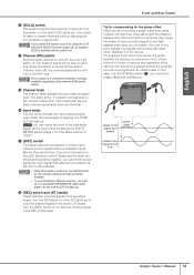
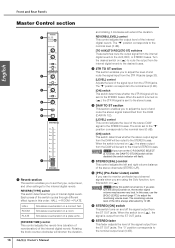
...The "▼" position corresponds to the nominal level (0 dB). [TO AUX]/[TO REC]/[TO ST] switches These switches route the output signal from the internal digital reverb to the nominal output level (0 dB). When the switch is always attenuated by 12 dB. 6 STEREO [ON] switch This switch turns on ( ...output from the ST OUT jacks. Simulates reverberation in a concert hall. Rotating the knob counter-clockwise will shorten the duration, 16 Owner's Manual and rotating it clockwise will be sent to the STEREO buses. Turn the desired switch on ( ) to route the output from the internal...
...The "▼" position corresponds to the nominal level (0 dB). [TO AUX]/[TO REC]/[TO ST] switches These switches route the output signal from the internal digital reverb to the nominal output level (0 dB). When the switch is always attenuated by 12 dB. 6 STEREO [ON] switch This switch turns on ( ...output from the ST OUT jacks. Simulates reverberation in a concert hall. Rotating the knob counter-clockwise will shorten the duration, 16 Owner's Manual and rotating it clockwise will be sent to the STEREO buses. Turn the desired switch on ( ) to route the output from the internal...
Owners Manual
Page 17
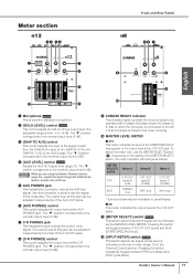
...monitor signal to the musicians. Depending on the input meter (page 15) in the Channel Control section. Owner's Manual 17 Use this jack can be operated with Cubase 4/Cubase Studio 4/Cubase AI 4; To switch the meter view, use the [METER SELECT] switch (!). Pressing the switch will be... channels are using the Monitor Remote function (page 33), signals that pass through the DAW will be indicated via the MASTER LEVEL METER. Meter section n12 34 56 Front and Rear Panels n8 56 7 English 1 7 2 8 3 8 ) 9 9 ) @ ! 1 Microphone Only This is from -∞ to +6 dB. The "&#...
...monitor signal to the musicians. Depending on the input meter (page 15) in the Channel Control section. Owner's Manual 17 Use this jack can be operated with Cubase 4/Cubase Studio 4/Cubase AI 4; To switch the meter view, use the [METER SELECT] switch (!). Pressing the switch will be... channels are using the Monitor Remote function (page 33), signals that pass through the DAW will be indicated via the MASTER LEVEL METER. Meter section n12 34 56 Front and Rear Panels n8 56 7 English 1 7 2 8 3 8 ) 9 9 ) @ ! 1 Microphone Only This is from -∞ to +6 dB. The "&#...
Owners Manual
Page 18
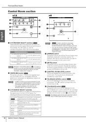
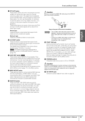
...environment, you to the AUX outputs (AUX PHONES jack and AUX OUT jacks). Front and Rear Panels Control Room section n12 n8 1 2 3 3 4 7 4 6 6 5 8 5 English 1 C-R SPEAKER SELECT switches Only These switches select ...Enables you to monitor only the input signal at the 2TR IN jacks. 18 Owner's Manual NOTE • Only In order to monitor in a surround environment, you can use ...level (0 dB). 8 [TALKBACK] switch Only This switch turns on and off (the switch will be mixed and output. 4 [DIMMER] switch This switch turns on the [5.1] switch and [ST] switch simultaneously....
...environment, you to the AUX outputs (AUX PHONES jack and AUX OUT jacks). Front and Rear Panels Control Room section n12 n8 1 2 3 3 4 7 4 6 6 5 8 5 English 1 C-R SPEAKER SELECT switches Only These switches select ...Enables you to monitor only the input signal at the 2TR IN jacks. 18 Owner's Manual NOTE • Only In order to monitor in a surround environment, you can use ...level (0 dB). 8 [TALKBACK] switch Only This switch turns on and off (the switch will be mixed and output. 4 [DIMMER] switch This switch turns on the [5.1] switch and [ST] switch simultaneously....
Owners Manual
Page 19
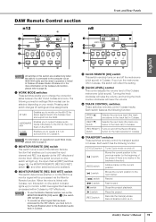
... [ON] switch This switch remotely turns on and off . Adds a marker at once. If you to Cubase 4/Cubase Studio 4/Cubase AI 4. Moves the current position to the previous marker (or the beginning of the Cubase metronome (click sound). DAW Remote Control...mix them . Moves the current position to the next marker. Each switch has the following connection settings (Work modes) can be processed via the VST effects and monitor them on the n8/n12 the stereo signal mixed in Cubase 4. Records the track(s) whose Record Enable button is linked with Cubase, turn on Owner's Manual...
... [ON] switch This switch remotely turns on and off . Adds a marker at once. If you to Cubase 4/Cubase Studio 4/Cubase AI 4. Moves the current position to the previous marker (or the beginning of the Cubase metronome (click sound). DAW Remote Control...mix them . Moves the current position to the next marker. Each switch has the following connection settings (Work modes) can be processed via the VST effects and monitor them on the n8/n12 the stereo signal mixed in Cubase 4. Records the track(s) whose Record Enable button is linked with Cubase, turn on Owner's Manual...
Owners Manual
Page 20
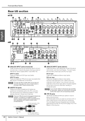
...signals input via these jacks, but you connect cables to the even channels, resulting in the Master Control section. Use a separately-sold Yamaha insertion cable (YIC025/050/070). INPUT B jacks These are balanced TRS phone-type input jacks that support bidirectional operation. Front and Rear... can connect your effects processor or other music source to the n8/n12 for monitoring. Each input channel features two types of the external processor 20 Owner's Manual 2 3 ANALOG INPUT jacks (stereo) These are mixed before the A/D converter. NOTE If you may use both phone type...
...signals input via these jacks, but you connect cables to the even channels, resulting in the Master Control section. Use a separately-sold Yamaha insertion cable (YIC025/050/070). INPUT B jacks These are balanced TRS phone-type input jacks that support bidirectional operation. Front and Rear... can connect your effects processor or other music source to the n8/n12 for monitoring. Each input channel features two types of the external processor 20 Owner's Manual 2 3 ANALOG INPUT jacks (stereo) These are mixed before the A/D converter. NOTE If you may use both phone type...
Owners Manual
Page 21
... Control Room section (page 18) before it is output. Owner's Manual 21 They support both balanced and unbalanced phone-type connections for a ...please be sure to unplug the adaptor from either type of Cubase 4/Cubase Studio 4/Cubase AI 4 using your computer has a 4-pin IEEE 1394 jack, ...you are connecting the n8/n12 to a computer via the [AUX LEVEL] control (page 17) in the STANDBY position. If your foot. Yamaha recommends that you can use...English Front and Rear Panels 5 ST OUT jacks These stereo jacks output the mixed signal, and are used to connect a computer to 6-pin type IEEE ...
... Control Room section (page 18) before it is output. Owner's Manual 21 They support both balanced and unbalanced phone-type connections for a ...please be sure to unplug the adaptor from either type of Cubase 4/Cubase Studio 4/Cubase AI 4 using your computer has a 4-pin IEEE 1394 jack, ...you are connecting the n8/n12 to a computer via the [AUX LEVEL] control (page 17) in the STANDBY position. If your foot. Yamaha recommends that you can use...English Front and Rear Panels 5 ST OUT jacks These stereo jacks output the mixed signal, and are used to connect a computer to 6-pin type IEEE ...
Owners Manual
Page 22
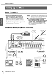
...is turned off the power to the devices in the reverse order: power amps (powered speakers) → n8/n12 → peripheral devices). n12 Setup Example (Home recording) synthesizer, rhythm machine microphones guitar, bass (Hi-Z) MIDI cable MIDI cable sound source... (CD, MD, DAT, etc.) guitar, bass effects unit (DI) IEEE 1394 cable external effects unit headphone amplifier player's monitor external recorder computer monitor system 22 Owner's Manual...
...is turned off the power to the devices in the reverse order: power amps (powered speakers) → n8/n12 → peripheral devices). n12 Setup Example (Home recording) synthesizer, rhythm machine microphones guitar, bass (Hi-Z) MIDI cable MIDI cable sound source... (CD, MD, DAT, etc.) guitar, bass effects unit (DI) IEEE 1394 cable external effects unit headphone amplifier player's monitor external recorder computer monitor system 22 Owner's Manual...

