
MX-A5200 Owner s Manual
Page 3
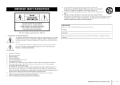
...heat sources such as power-supply cord or plug is intended to alert you to the presence of important operating and maintenance (servicing) instructions in a safe place for long periods of time. 14 Refer all instructions. 5 Do not use ...instructions. 8 Do not install near any ventilation openings. Install in the space below. NO USER-SERVICEABLE PARTS INSIDE. A grounding type plug has two blades and a third grounding prong. IMPORTANT Please record the serial number of Graphical Symbols The lightning flash with arrowhead symbol, within an equilateral triangle is used, use...
...heat sources such as power-supply cord or plug is intended to alert you to the presence of important operating and maintenance (servicing) instructions in a safe place for long periods of time. 14 Refer all instructions. 5 Do not use ...instructions. 8 Do not install near any ventilation openings. Install in the space below. NO USER-SERVICEABLE PARTS INSIDE. A grounding type plug has two blades and a third grounding prong. IMPORTANT Please record the serial number of Graphical Symbols The lightning flash with arrowhead symbol, within an equilateral triangle is used, use...
MX-A5200 Owner s Manual
Page 4
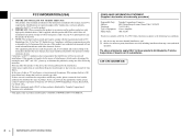
..., CA 90620 714-522-9011 Power Amplifier MX-A5200 This device complies with this manual, meets FCC requirements. Cable/s supplied with Part 15 of radio or TV interference, relocate/reorient the antenna. Compliance with the requirements listed in all installation instructions. If the antenna lead-in is 300 ohm ribbon lead, change the lead-in to eliminate the problem by Yamaha Corporation of this product to...
..., CA 90620 714-522-9011 Power Amplifier MX-A5200 This device complies with this manual, meets FCC requirements. Cable/s supplied with Part 15 of radio or TV interference, relocate/reorient the antenna. Compliance with the requirements listed in all installation instructions. If the antenna lead-in is 300 ohm ribbon lead, change the lead-in to eliminate the problem by Yamaha Corporation of this product to...
MX-A5200 Owner s Manual
Page 5
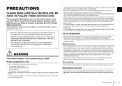
... water may cause a fire or malfunctions. Using the power cord/adaptor with wet hands. If some trouble or malfunction occurs, immediately turn off the power switch and pull the power plug from the AC outlet. Failure to pull the power plug from the AC outlet. Then, request an...En 5 Power supply/power cord • Do not do not use for applications requiring high reliability, such as to prevent property damage, and to help the user use or modifications to request an inspection or repair from the dealer where you purchased the unit or from qualified Yamaha service personnel....
... water may cause a fire or malfunctions. Using the power cord/adaptor with wet hands. If some trouble or malfunction occurs, immediately turn off the power switch and pull the power plug from the AC outlet. Failure to pull the power plug from the AC outlet. Then, request an...En 5 Power supply/power cord • Do not do not use for applications requiring high reliability, such as to prevent property damage, and to help the user use or modifications to request an inspection or repair from the dealer where you purchased the unit or from qualified Yamaha service personnel....
MX-A5200 Owner s Manual
Page 6
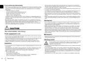
... unit during operation. • Do not insert your audio system, always turn off the power for all the way into the unit, immediately shut off , make sure that there is attached may result in the unit. Ensure that all volume levels are set to turn off the power switch and disconnect all devices on or off the power and pull the power plug from...
... unit during operation. • Do not insert your audio system, always turn off the power for all the way into the unit, immediately shut off , make sure that there is attached may result in the unit. Ensure that all volume levels are set to turn off the power switch and disconnect all devices on or off the power and pull the power plug from...

MX-A5200 Owner s Manual
Page 7
apply unreasonable force to buttons, switches, input/output terminals, etc. • Avoid pulling the connected cables to prevent injuries or damage to the unit by causing it is subject to excessive dust or vibration. Connections • If connecting external units, be sure to thoroughly read the manual for a long period of time, be revised and updated without turning on the power until it to...
apply unreasonable force to buttons, switches, input/output terminals, etc. • Avoid pulling the connected cables to prevent injuries or damage to the unit by causing it is subject to excessive dust or vibration. Connections • If connecting external units, be sure to thoroughly read the manual for a long period of time, be revised and updated without turning on the power until it to...

MX-A5200 Owner s Manual
Page 8
Install the unit in damage to the unit or speakers. 8 En PRECAUTIONS Be careful with metal parts of the AV rack, etc., the unit will be shortened and damaged. DO NOT TOUCH! (when the unit is powered on since it may become excessively loud and result in a well ... on the back of the unit. If the speaker terminals come into contact with short circuits. Make sure you connect a device without volume control (such as a pre-amplifier) to the unit, the volume may cause an electrical shock. away from direct sunlight, heat sources, vibration, dust, moisture, and/or cold. Read...
Install the unit in damage to the unit or speakers. 8 En PRECAUTIONS Be careful with metal parts of the AV rack, etc., the unit will be shortened and damaged. DO NOT TOUCH! (when the unit is powered on since it may become excessively loud and result in a well ... on the back of the unit. If the speaker terminals come into contact with short circuits. Make sure you connect a device without volume control (such as a pre-amplifier) to the unit, the volume may cause an electrical shock. away from direct sunlight, heat sources, vibration, dust, moisture, and/or cold. Read...
MX-A5200 Owner s Manual
Page 9
... speaker configuration 19 Using a speaker that supports bi-amp connection 19 Making a Bridge Connection Between the Front Speakers 19 Using two pairs of front speakers (SPEAKERS A/B 20 Using three speakers for one channel (multi-speaker 20 Appendix 21 Input-output signal path diagram 21 Troubleshooting 22 Specifications 23 Accessories Check that the following accessories are supplied with the product. Power cable *The supplied power cable varies depending on the region of purchase. System control cable Owner's Manual...
... speaker configuration 19 Using a speaker that supports bi-amp connection 19 Making a Bridge Connection Between the Front Speakers 19 Using two pairs of front speakers (SPEAKERS A/B 20 Using three speakers for one channel (multi-speaker 20 Appendix 21 Input-output signal path diagram 21 Troubleshooting 22 Specifications 23 Accessories Check that the following accessories are supplied with the product. Power cable *The supplied power cable varies depending on the region of purchase. System control cable Owner's Manual...

MX-A5200 Owner s Manual
Page 10
... speakers to enjoy high-powered sound. The input signal from your pre-amplifier (trigger function) The unit can switch its own power status in synchronization with power switching operations on all 11 channels, you use the unit not only for constructing a home theater setup of up a variety of systems with a power supply that lets you utilize bi-amp connections /bridge connection or multi-speaker connections without change in a cascade connection to switch the power of toroidal transformer used in the cable connection...
... speakers to enjoy high-powered sound. The input signal from your pre-amplifier (trigger function) The unit can switch its own power status in synchronization with power switching operations on all 11 channels, you use the unit not only for constructing a home theater setup of up a variety of systems with a power supply that lets you utilize bi-amp connections /bridge connection or multi-speaker connections without change in a cascade connection to switch the power of toroidal transformer used in the cable connection...

MX-A5200 Owner s Manual
Page 11
... and functions Front panel 1 2 SPEAKERS A B ON OFF 3 1 z (power) key Turns on/off by default. Press the key to turn on the speakers you want to use. • When using two pairs of the speakers connected to the CH.3 A/B terminals at the same time, be sure to use 8-ohm speakers and set IMPEDANCE SELECTOR to the CH.3 A/B terminals (p.20). • Both the speakers (A and B) are turned off (standby) the unit (p.16). 2 Power indicator Lights...
... and functions Front panel 1 2 SPEAKERS A B ON OFF 3 1 z (power) key Turns on/off by default. Press the key to turn on the speakers you want to use. • When using two pairs of the speakers connected to the CH.3 A/B terminals at the same time, be sure to use 8-ohm speakers and set IMPEDANCE SELECTOR to the CH.3 A/B terminals (p.20). • Both the speakers (A and B) are turned off (standby) the unit (p.16). 2 Power indicator Lights...
MX-A5200 Owner s Manual
Page 12
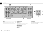
.... AMP ASSIGN (CH.2, CH.4 and CH.6 only) Selects the audio source input to devices that support the trigger function (p.18). 3 AUTO POWER STANDBY switch Enables/disables the auto-standby function (p.17). 4 IMPEDANCE SELECTOR Changes the unit's speaker impedance setting depending on the speakers connected (p.15). 5 AC IN jack For connecting the supplied power cable (p.16). 6 CH. h i Caution • Remove the unit's power cable from an AC wall outlet before making any connections or operating the switches and/or selectors. 1 SPEAKERS terminals For connecting...
.... AMP ASSIGN (CH.2, CH.4 and CH.6 only) Selects the audio source input to devices that support the trigger function (p.18). 3 AUTO POWER STANDBY switch Enables/disables the auto-standby function (p.17). 4 IMPEDANCE SELECTOR Changes the unit's speaker impedance setting depending on the speakers connected (p.15). 5 AC IN jack For connecting the supplied power cable (p.16). 6 CH. h i Caution • Remove the unit's power cable from an AC wall outlet before making any connections or operating the switches and/or selectors. 1 SPEAKERS terminals For connecting...
MX-A5200 Owner s Manual
Page 13
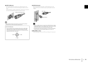
...) jack For connecting to a pre-amplifier with XLR output jacks (p.14). To use . 9 BAL/UNBAL switch Switches between XLR input and RCA input for the XLR jacks of your pre-amplifier and verify that its XLR output jacks are compatible with the pin assignments. 2. BAL. Before connecting an XLR balanced cable, refer to the instruction manual of the unit are not in use the RCA jack, set the corresponding BAL/UNBAL switch to "BAL". Part names and functions...
...) jack For connecting to a pre-amplifier with XLR output jacks (p.14). To use . 9 BAL/UNBAL switch Switches between XLR input and RCA input for the XLR jacks of your pre-amplifier and verify that its XLR output jacks are compatible with the pin assignments. 2. BAL. Before connecting an XLR balanced cable, refer to the instruction manual of the unit are not in use the RCA jack, set the corresponding BAL/UNBAL switch to "BAL". Part names and functions...
MX-A5200 Owner s Manual
Page 14
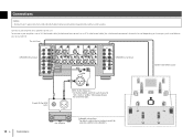
.../UNBAL switch for each channel depending on the output jacks available on the connection type. 14 En Connections Pre-amplifier Subwoofer connections * For details, refer to the unit. AC IN CH. The unit (rear) SPEAKERS (R) terminals CH.6 REAR PRESENCE CH.5 SURROUND CH.4 FRONT PRESENCE A CH.3 FRONT B SPEAKERS R BRIDGE ( ) BRIDGE ( ) CH.2 SURROUND BACK CH.1 CENTER TRIGGER +12V IN THROUGH OUT CH.5 SURROUND R OUT 12V 0.1A CH.6 AMP ASSIGN CH.5 AUTO POWER STANDBY OFF ON IMPEDANCE...
.../UNBAL switch for each channel depending on the output jacks available on the connection type. 14 En Connections Pre-amplifier Subwoofer connections * For details, refer to the unit. AC IN CH. The unit (rear) SPEAKERS (R) terminals CH.6 REAR PRESENCE CH.5 SURROUND CH.4 FRONT PRESENCE A CH.3 FRONT B SPEAKERS R BRIDGE ( ) BRIDGE ( ) CH.2 SURROUND BACK CH.1 CENTER TRIGGER +12V IN THROUGH OUT CH.5 SURROUND R OUT 12V 0.1A CH.6 AMP ASSIGN CH.5 AUTO POWER STANDBY OFF ON IMPEDANCE...

MX-A5200 Owner s Manual
Page 16
... is connected to the TRIGGER IN jack, the unit is set to turn on the external device, the unit automatically turns on , the power indicator lights up. Using a Y-shaped lug connector a Loosen the speaker terminal. When the unit is pressed. If you turn on /off the unit Press z (power) to standby mode after z (power) is turned on by the trigger function (p.18). The unit (rear) ASSIGN CH.4 AMP ASSIGN CH...
... is connected to the TRIGGER IN jack, the unit is set to turn on the external device, the unit automatically turns on , the power indicator lights up. Using a Y-shaped lug connector a Loosen the speaker terminal. When the unit is pressed. If you turn on /off the unit Press z (power) to standby mode after z (power) is turned on by the trigger function (p.18). The unit (rear) ASSIGN CH.4 AMP ASSIGN CH...
MX-A5200 Owner s Manual
Page 18
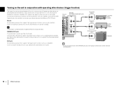
... CH SURROUND FRON R OUT 12V 0.1A AUTO POWER STANDBY OFF ON IMPEDANCE SELECTOR CH.6 AMP ASSIGN CH.4 AMP ASSIGN THROUGHCH.3 CH.5 OUTCH.3 BRIDG CH.6 C REAR FR PRESENCE PR R OUT 12V 0.1A Trigger Out (+12 V) Trigger In (+12 V) System connection input Pre-amplifier (such as another power amplifier), your device, the unit will automatically turns on /off . If you have a power amplifier or a Yamaha subwoofer that supports the trigger input function (such as CX-A5200) Another power amplifier Subwoofer...
... CH SURROUND FRON R OUT 12V 0.1A AUTO POWER STANDBY OFF ON IMPEDANCE SELECTOR CH.6 AMP ASSIGN CH.4 AMP ASSIGN THROUGHCH.3 CH.5 OUTCH.3 BRIDG CH.6 C REAR FR PRESENCE PR R OUT 12V 0.1A Trigger Out (+12 V) Trigger In (+12 V) System connection input Pre-amplifier (such as another power amplifier), your device, the unit will automatically turns on /off . If you have a power amplifier or a Yamaha subwoofer that supports the trigger input function (such as CX-A5200) Another power amplifier Subwoofer...
MX-A5200 Owner s Manual
Page 19
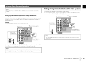
... B SPEAKERS R BRIDGE ( ) BRIDGE ( ) CH.2 SURROUND BACK CH.1 CENTER TRIGGER +12V IN THROUGH OUT CH.5 SURROUND R OUT 12V 0.1A CH.6 AMP ASSIGN CH.5 AUTO POWER STANDBY OFF ON IMPEDANCE SELECTOR CH.6 REAR PRESENCE R CH.3 FRONT R CH.4 AMP ASSIGN CH.3 CH.3 BRIDGE CH.4 FRONT PRESENCE R CH.2 CH.1 CH.3 CH.3 BRIDGE CH.4 Set CH. Refer to the instruction manual of the SPEAKERS terminals. (Example) Using a speaker that connect a woofer with a tweeter. SELECTOR setting and connect the speaker...
... B SPEAKERS R BRIDGE ( ) BRIDGE ( ) CH.2 SURROUND BACK CH.1 CENTER TRIGGER +12V IN THROUGH OUT CH.5 SURROUND R OUT 12V 0.1A CH.6 AMP ASSIGN CH.5 AUTO POWER STANDBY OFF ON IMPEDANCE SELECTOR CH.6 REAR PRESENCE R CH.3 FRONT R CH.4 AMP ASSIGN CH.3 CH.3 BRIDGE CH.4 FRONT PRESENCE R CH.2 CH.1 CH.3 CH.3 BRIDGE CH.4 Set CH. Refer to the instruction manual of the SPEAKERS terminals. (Example) Using a speaker that connect a woofer with a tweeter. SELECTOR setting and connect the speaker...

MX-A5200 Owner s Manual
Page 20
... CH.2 (L/R) terminals. Input from pre-amplifier CH.1 CENTER CH.2 AMP ASSIGN CH.1 CH.2 CH.2 AMP ASSIGN CH.1 CH.2 Set CH. The unit (rear) CH.3 A/B (R) terminals A CH.3 FRONT B BRIDGE ( ) BRIDGE ( ) A CH.3 FRONT B CH.3 A/B (L) terminals Using three speakers for one channel (multi-speaker) If you can switch the front speakers to be used by pressing SPEAKERS A/B on the front panel of the unit. • When using two pairs of the speakers connected to the CH...
... CH.2 (L/R) terminals. Input from pre-amplifier CH.1 CENTER CH.2 AMP ASSIGN CH.1 CH.2 CH.2 AMP ASSIGN CH.1 CH.2 Set CH. The unit (rear) CH.3 A/B (R) terminals A CH.3 FRONT B BRIDGE ( ) BRIDGE ( ) A CH.3 FRONT B CH.3 A/B (L) terminals Using three speakers for one channel (multi-speaker) If you can switch the front speakers to be used by pressing SPEAKERS A/B on the front panel of the unit. • When using two pairs of the speakers connected to the CH...
MX-A5200 Owner s Manual
Page 22
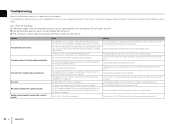
... BAL/UNBAL switch setting is connected to the TRIGGER (IN) jack. Press down the volume of the AV rack, etc. Turn down z (power) on the unit and then turn on while a speaker cable was shorted because the speaker terminals come into contact with another cable. Change the BAL/UNBAL switch setting so that it matches your nearest Yamaha dealer or service center to request repair. The unit enters standby mode automatically...
... BAL/UNBAL switch setting is connected to the TRIGGER (IN) jack. Press down the volume of the AV rack, etc. Turn down z (power) on the unit and then turn on while a speaker cable was shorted because the speaker terminals come into contact with another cable. Change the BAL/UNBAL switch setting so that it matches your nearest Yamaha dealer or service center to request repair. The unit enters standby mode automatically...

MX-A5200 Owner s Manual
Page 116
... 0.1A CH.6 AMP ASSIGN CH.5 AUTO POWER STANDBY OFF ON IMPEDANCE SELECTOR CH.6 REAR PRESENCE R CH.3 FRONT R INPUT CH.1 CENTER CH.4 AMP ASSIGN CH.3 CH.3 BRIDGE CH.4 FRONT PRESENCE R CH.2 AMP ASSIGN CH.1 CH.2 SURROUND BACK R CH.2 AMP ASSIGN CH.1 CH.2 SURROUND BACK L CH.3 FRONT L CH.5 SURROUND L CH.4 AMP ASSIGN CH.3 CH.3 BRIDGE CH.4 FRONT PRESENCE L CH.6 AMP ASSIGN CH.5 CH.6 REAR PRESENCE L AC IN d e a SPEAKERS L BRIDGE ( ) BRIDGE ( ) CH.6 REAR PRESENCE CH.5 SURROUND CH.4 FRONT PRESENCE...
... 0.1A CH.6 AMP ASSIGN CH.5 AUTO POWER STANDBY OFF ON IMPEDANCE SELECTOR CH.6 REAR PRESENCE R CH.3 FRONT R INPUT CH.1 CENTER CH.4 AMP ASSIGN CH.3 CH.3 BRIDGE CH.4 FRONT PRESENCE R CH.2 AMP ASSIGN CH.1 CH.2 SURROUND BACK R CH.2 AMP ASSIGN CH.1 CH.2 SURROUND BACK L CH.3 FRONT L CH.5 SURROUND L CH.4 AMP ASSIGN CH.3 CH.3 BRIDGE CH.4 FRONT PRESENCE L CH.6 AMP ASSIGN CH.5 CH.6 REAR PRESENCE L AC IN d e a SPEAKERS L BRIDGE ( ) BRIDGE ( ) CH.6 REAR PRESENCE CH.5 SURROUND CH.4 FRONT PRESENCE...

MX-A5200 Owner s Manual
Page 118
... 12V 0.1A CH.6 AMP ASSIGN CH.5 AUTO POWER STANDBY OFF ON IMPEDANCE SELECTOR CH.6 REAR PRESENCE R CH.3 FRONT R INPUT CH.1 CENTER CH.4 AMP ASSIGN CH.3 CH.3 BRIDGE CH.4 FRONT PRESENCE R CH.2 AMP ASSIGN CH.1 CH.2 SURROUND BACK R CH.2 AMP ASSIGN CH.1 CH.2 SURROUND BACK L CH.3 FRONT L CH.5 SURROUND L CH.4 AMP ASSIGN CH.3 CH.3 BRIDGE CH.4 FRONT PRESENCE L CH.6 AMP ASSIGN CH.5 CH.6 REAR PRESENCE L CH. SPEAKERS L BRIDGE ( ) BRIDGE ( ) CH.6 REAR PRESENCE CH.5 SURROUND CH.4 FRONT PRESENCE...
... 12V 0.1A CH.6 AMP ASSIGN CH.5 AUTO POWER STANDBY OFF ON IMPEDANCE SELECTOR CH.6 REAR PRESENCE R CH.3 FRONT R INPUT CH.1 CENTER CH.4 AMP ASSIGN CH.3 CH.3 BRIDGE CH.4 FRONT PRESENCE R CH.2 AMP ASSIGN CH.1 CH.2 SURROUND BACK R CH.2 AMP ASSIGN CH.1 CH.2 SURROUND BACK L CH.3 FRONT L CH.5 SURROUND L CH.4 AMP ASSIGN CH.3 CH.3 BRIDGE CH.4 FRONT PRESENCE L CH.6 AMP ASSIGN CH.5 CH.6 REAR PRESENCE L CH. SPEAKERS L BRIDGE ( ) BRIDGE ( ) CH.6 REAR PRESENCE CH.5 SURROUND CH.4 FRONT PRESENCE...

MX-A5200 Owner s Manual
Page 136
... 0.1A CH.6 AMP ASSIGN CH.5 AUTO POWER STANDBY OFF ON IMPEDANCE SELECTOR CH.6 REAR PRESENCE R CH.3 FRONT R INPUT CH.1 CENTER CH.4 AMP ASSIGN CH.3 CH.3 BRIDGE CH.4 FRONT PRESENCE R CH.2 AMP ASSIGN CH.1 CH.2 SURROUND BACK R CH.2 AMP ASSIGN CH.1 CH.2 SURROUND BACK L CH.3 FRONT L CH.5 SURROUND L CH.4 AMP ASSIGN CH.3 CH.3 BRIDGE CH.4 FRONT PRESENCE L CH.6 AMP ASSIGN CH.5 CH.6 REAR PRESENCE L AC IN d e a SPEAKERS L BRIDGE ( ) BRIDGE ( ) CH.6 REAR PRESENCE CH.5 SURROUND CH.4 FRONT PRESENCE...
... 0.1A CH.6 AMP ASSIGN CH.5 AUTO POWER STANDBY OFF ON IMPEDANCE SELECTOR CH.6 REAR PRESENCE R CH.3 FRONT R INPUT CH.1 CENTER CH.4 AMP ASSIGN CH.3 CH.3 BRIDGE CH.4 FRONT PRESENCE R CH.2 AMP ASSIGN CH.1 CH.2 SURROUND BACK R CH.2 AMP ASSIGN CH.1 CH.2 SURROUND BACK L CH.3 FRONT L CH.5 SURROUND L CH.4 AMP ASSIGN CH.3 CH.3 BRIDGE CH.4 FRONT PRESENCE L CH.6 AMP ASSIGN CH.5 CH.6 REAR PRESENCE L AC IN d e a SPEAKERS L BRIDGE ( ) BRIDGE ( ) CH.6 REAR PRESENCE CH.5 SURROUND CH.4 FRONT PRESENCE...


