
Service Manual
Page 1
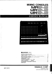
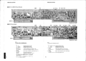
... '89.8 ffi = Mr IMM = M = MI= M M Lia SERVICE MANUAL 0.. * 0,0 " 0 6 6 "6 * 6 86 0. 0 41:1, 0 00 0 6 0 0 0 0 ******0•0********* anliall tal1110inMilEMIMI11111 ININBBElIIIIll IIIMI LM 006910 ECONTENTS ( ) SPECIFICATIONS (4e*l±a) 2 PANEL LAYOUT (/ -17 r, ) 6 BLOCK & LEVEL DIAGRAM ( 7'. & 7 A) 8 CIRCUIT BOARD LAYOUT (3_:: -(7 r7 F ) 10 DIMENSIONS (7k:A ) 1 1 IC BLOCK DIAGRAM (ic "ln LI) 11 CIRCUIT BOARDS ( v - h 4* ) 12 DISASSEMBLY PROCEDURE(-5-1W*IIIR) 24 PARTS LIST YAMAHA CORP. MIXING/NM CONSOLES d=ft IMrmaM I= W SMN M MM IMP I=W WWI i fL...
... '89.8 ffi = Mr IMM = M = MI= M M Lia SERVICE MANUAL 0.. * 0,0 " 0 6 6 "6 * 6 86 0. 0 41:1, 0 00 0 6 0 0 0 0 ******0•0********* anliall tal1110inMilEMIMI11111 ININBBElIIIIll IIIMI LM 006910 ECONTENTS ( ) SPECIFICATIONS (4e*l±a) 2 PANEL LAYOUT (/ -17 r, ) 6 BLOCK & LEVEL DIAGRAM ( 7'. & 7 A) 8 CIRCUIT BOARD LAYOUT (3_:: -(7 r7 F ) 10 DIMENSIONS (7k:A ) 1 1 IC BLOCK DIAGRAM (ic "ln LI) 11 CIRCUIT BOARDS ( v - h 4* ) 12 DISASSEMBLY PROCEDURE(-5-1W*IIIR) 24 PARTS LIST YAMAHA CORP. MIXING/NM CONSOLES d=ft IMrmaM I= W SMN M MM IMP I=W WWI i fL...
Service Manual
Page 2
... gauge black wires connect to retrofit. IMPORTANT: Turn the unit OFF during disassembly and parts replacement. For these reasons, we advise all Yamaha product owners that basic service procedures inherent to perform as specified. The data provided is believed to be performed by an authorized Yamaha Retailer or the appointed service representative. Modifications are, therefore, inevitable and changes in specification are continually...
... gauge black wires connect to retrofit. IMPORTANT: Turn the unit OFF during disassembly and parts replacement. For these reasons, we advise all Yamaha product owners that basic service procedures inherent to perform as specified. The data provided is believed to be performed by an authorized Yamaha Retailer or the appointed service representative. Modifications are, therefore, inevitable and changes in specification are continually...
Service Manual
Page 3
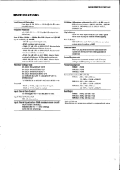
..., adjacent channel inputs. -60 dB at AUX SEND, Master fader and one channel fader nominal. -70 dB (74 dB S/N) at AUX SEND, Master fader nominal, all channel AUX controls minimum. - 64 dB (68 dB S/N) at 1 kHz, input to electronically balanced inputs (via 6.81(S/current limiting/isolation resistors). VU Meters (All meters calibrated for 0 VU = +4 dB output) 6 illuminated meters: GROUP 1/AUX 1, GROUP 2/AUX 2, GROUP 3/AUX 3, GROUP 4/CUE, STEREO L/R Clip Indicators LEDs for each VU meter. Power Consumption MR842 :70 W MR1242 : 70 W MR1642 : 70 W Console Dimensions (W x H x D) MR842...
..., adjacent channel inputs. -60 dB at AUX SEND, Master fader and one channel fader nominal. -70 dB (74 dB S/N) at AUX SEND, Master fader nominal, all channel AUX controls minimum. - 64 dB (68 dB S/N) at 1 kHz, input to electronically balanced inputs (via 6.81(S/current limiting/isolation resistors). VU Meters (All meters calibrated for 0 VU = +4 dB output) 6 illuminated meters: GROUP 1/AUX 1, GROUP 2/AUX 2, GROUP 3/AUX 3, GROUP 4/CUE, STEREO L/R Clip Indicators LEDs for each VU meter. Power Consumption MR842 :70 W MR1242 : 70 W MR1642 : 70 W Console Dimensions (W x H x D) MR842...
Service Manual
Page 5
...-ct Output Terminals GROUP OUT (1 4) STEREO OUT(L,R) AUX SEND (1 3) INSERT OUT CH(1x) GROUP(1 4) MONITOR OUT (L, R) PHONE OUT Actual Source Impedance 150 11 600 11 150 12 600 Cl 150 fl 600 SZ 600 Cl 10012 For Use With Nominal 600 fi Lines 10k 12 Lines 600 Cl Lines 10k 12 Lines 600 Cl Lines 10k 12 Lines 10k Cl Lines 812 phones 40 1/ phones Output Level Nominal...
...-ct Output Terminals GROUP OUT (1 4) STEREO OUT(L,R) AUX SEND (1 3) INSERT OUT CH(1x) GROUP(1 4) MONITOR OUT (L, R) PHONE OUT Actual Source Impedance 150 11 600 11 150 12 600 Cl 150 fl 600 SZ 600 Cl 10012 For Use With Nominal 600 fi Lines 10k 12 Lines 600 Cl Lines 10k 12 Lines 600 Cl Lines 10k 12 Lines 10k Cl Lines 812 phones 40 1/ phones Output Level Nominal...
Service Manual
Page 6
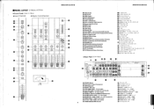
MR842/MR1242/MR1642 "PANEL LAYOUT (i
MR842/MR1242/MR1642 "PANEL LAYOUT (i
Service Manual
Page 7
...- L GROUP SUB 1N(4,11 CUE GROUP. STEREO AUX STEREO SUB IN(+4) AUX SENO 3 to MONITOR -\ +40 GROUP.STEREO.AU)( SENO.MONITOR(+4) +10 STEREO / % -LI ▪0 C o O z GROUP.STEREO(-10) 10 PHONES(101W) -20 -30 -40 -50 -60 *1 AUX 1.2 PRE E0/POST EO JUMPER *2 AUX 1 POST FADER/PRE FADER JUMPER *3 AUX 2 PRE FADER/POST FADER JUMPER *4 GROUP CUE PFL/AFL JUMPER *5 AUX SEND CUE PFL/AFL JUMPER • 000.0.775V XX CLIP LED TURN ON LEVEL.-3(3 BEFORE CLIP(+17C1B) *** LED PEAK METER OVU.+4410 **** ANALOG METER OVU...
...- L GROUP SUB 1N(4,11 CUE GROUP. STEREO AUX STEREO SUB IN(+4) AUX SENO 3 to MONITOR -\ +40 GROUP.STEREO.AU)( SENO.MONITOR(+4) +10 STEREO / % -LI ▪0 C o O z GROUP.STEREO(-10) 10 PHONES(101W) -20 -30 -40 -50 -60 *1 AUX 1.2 PRE E0/POST EO JUMPER *2 AUX 1 POST FADER/PRE FADER JUMPER *3 AUX 2 PRE FADER/POST FADER JUMPER *4 GROUP CUE PFL/AFL JUMPER *5 AUX SEND CUE PFL/AFL JUMPER • 000.0.775V XX CLIP LED TURN ON LEVEL.-3(3 BEFORE CLIP(+17C1B) *** LED PEAK METER OVU.+4410 **** ANALOG METER OVU...
Service Manual
Page 8
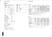
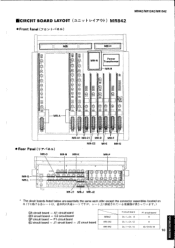
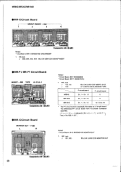
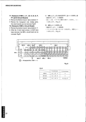
...;A circuit board - MCIRCUIT BOARD LAYOUT (.a_ •i h 1, 4 7 ,7 h ) MR842 • Front Panel (7 a ;/ ,1 01 0 1 1..3;-., reoA- (r9) @ @ 4.,5) @ 0 • •-:/ 7' 7 ,r g< MR-Jl MR-J MR-J2 • The circuit boards listed below are essentially the same each other except the connector assemblies located on it. Al circuit board ®Cl circuit board - C2 circuit board ®P circuit board - J2 circut board MR842 MR1242 MR1642 P circuit board Ch...
...;A circuit board - MCIRCUIT BOARD LAYOUT (.a_ •i h 1, 4 7 ,7 h ) MR842 • Front Panel (7 a ;/ ,1 01 0 1 1..3;-., reoA- (r9) @ @ 4.,5) @ 0 • •-:/ 7' 7 ,r g< MR-Jl MR-J MR-J2 • The circuit boards listed below are essentially the same each other except the connector assemblies located on it. Al circuit board ®Cl circuit board - C2 circuit board ®P circuit board - J2 circut board MR842 MR1242 MR1642 P circuit board Ch...
Service Manual
Page 10
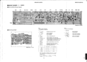
... PAN RS60Y11G4023- (HX802030) 10KA-PJ Fader SPUE20AE08-PJ (KX801930) TAPE, PAD SPUE30AE24-PJ (KX801920) TAPE, 1-2, 3-4 KPB122-SNAL (KX800750) CUE Notes) • Circuit Board: MR-B (NX806660) 1. HIGH CLIP GAIN PAD TAPE LOW MID MID FREQ. ao 0 RI61 C103... circuit board from A are Connector assembly Ti and T2. (A h S( _rC n K17 , A - MR842/MR1242/MR1642 MR842/MR1242/MR1642 MCIRCUIT BOARDS F40 •MR-A & MR-Al Circuit Boards GROUP. 1 -8 [CUEI C SW106 PAN PAN 3-4 TAPE GROUP 43 2 1 TAPE I I I I I I II I I I 1 SW104 SW103 LEVEL VR AUX3 AUX2 AUX1 AUX 3 AUX 2 ...
... PAN RS60Y11G4023- (HX802030) 10KA-PJ Fader SPUE20AE08-PJ (KX801930) TAPE, PAD SPUE30AE24-PJ (KX801920) TAPE, 1-2, 3-4 KPB122-SNAL (KX800750) CUE Notes) • Circuit Board: MR-B (NX806660) 1. HIGH CLIP GAIN PAD TAPE LOW MID MID FREQ. ao 0 RI61 C103... circuit board from A are Connector assembly Ti and T2. (A h S( _rC n K17 , A - MR842/MR1242/MR1642 MR842/MR1242/MR1642 MCIRCUIT BOARDS F40 •MR-A & MR-Al Circuit Boards GROUP. 1 -8 [CUEI C SW106 PAN PAN 3-4 TAPE GROUP 43 2 1 TAPE I I I I I I II I I I 1 SW104 SW103 LEVEL VR AUX3 AUX2 AUX1 AUX 3 AUX 2 ...
Service Manual
Page 11
... 572 T `` .1. ,-\...-'11 I i I (ip (4; ) elg41O k g...11 cC32 2 dG kr> a 1 ;i t0 t an , M en 9/11 N yy ac • GROUP1, 2 Lz W11W13 LEVEL v ,ANIRIPIRS91191111991EPMMICIIV. I i -. .--- en ;!› 1.- .* ...;.1.:-...` :...e eif"11 .t,-.' C - r* in C175 -III .' x .);,`'L; IC 512, 572: NJM4558DV (IG001390) OP AMP. 2. p/T -4 l- t'' Components side OSai gn CUE AUX SEND 3 CUE' AUX SEND 2 CUE AUX SEND1 MR --D -. ( W13 ..- W12. •MR-D Circuit Board VR306 I ,4 l1i :1 li ,, i x x T29 T16 1 [ cu( PAN A 7, f.) J.'
... 572 T `` .1. ,-\...-'11 I i I (ip (4; ) elg41O k g...11 cC32 2 dG kr> a 1 ;i t0 t an , M en 9/11 N yy ac • GROUP1, 2 Lz W11W13 LEVEL v ,ANIRIPIRS91191111991EPMMICIIV. I i -. .--- en ;!› 1.- .* ...;.1.:-...` :...e eif"11 .t,-.' C - r* in C175 -III .' x .);,`'L; IC 512, 572: NJM4558DV (IG001390) OP AMP. 2. p/T -4 l- t'' Components side OSai gn CUE AUX SEND 3 CUE' AUX SEND 2 CUE AUX SEND1 MR --D -. ( W13 ..- W12. •MR-D Circuit Board VR306 I ,4 l1i :1 li ,, i x x T29 T16 1 [ cu( PAN A 7, f.) J.'

Service Manual
Page 12
...) V161.4N15KC CUE -15KC10Kx2 (HX805000) V16L G3-1CN15KC MONITOR RS60Y11G4023- (HX802030) 10KA-PJ ST-L SPUE30AE23-PJ (KX801900) CUE, AUX 3, ST 16 17 Potentiometer VR 203, 204: 7. i.3; C 3 N027 T2 I 4. 1 7 9 - „ 41. Diode D 201-204: 4. NJM4556 (1G042500) OP AMP. 2SC1313 OX802930) 2SA726 OX802920) 1N6OP (IF000620) -15A25Kx2 (HX802000) V1614 N15KCG3-1 PAN RS60Y11G4023- (HX802030) 10KA-PJ GROUP 4 Fader 50KB 3P (HX802040...
...) V161.4N15KC CUE -15KC10Kx2 (HX805000) V16L G3-1CN15KC MONITOR RS60Y11G4023- (HX802030) 10KA-PJ ST-L SPUE30AE23-PJ (KX801900) CUE, AUX 3, ST 16 17 Potentiometer VR 203, 204: 7. i.3; C 3 N027 T2 I 4. 1 7 9 - „ 41. Diode D 201-204: 4. NJM4556 (1G042500) OP AMP. 2SC1313 OX802930) 2SA726 OX802920) 1N6OP (IF000620) -15A25Kx2 (HX802000) V1614 N15KCG3-1 PAN RS60Y11G4023- (HX802030) 10KA-PJ GROUP 4 Fader 50KB 3P (HX802040...

Service Manual
Page 14
..., 304, 403, 404: 50KB 3P (HX802040) PEAK adj. 6. MIC Jack J 201, 202: RDJ-245 (LX801230) SUB IN " The J1 (J2) circuit board is only the length of wires of connector assembly. ( J , J 1, J - \ - I (NX806730) VU meters (AUX/CUE) 1. irroODAnODROW.,Li3 C445 tq.r; Slide Switch SW 303, 304, 405, 406: SSSB222NF1-PJ (KX801910) GROUP 1-4 7. C345 mu *358 R372 R370 C337 C338 VR303...
..., 304, 403, 404: 50KB 3P (HX802040) PEAK adj. 6. MIC Jack J 201, 202: RDJ-245 (LX801230) SUB IN " The J1 (J2) circuit board is only the length of wires of connector assembly. ( J , J 1, J - \ - I (NX806730) VU meters (AUX/CUE) 1. irroODAnODROW.,Li3 C445 tq.r; Slide Switch SW 303, 304, 405, 406: SSSB222NF1-PJ (KX801910) GROUP 1-4 7. C345 mu *358 R372 R370 C337 C338 VR303...
Service Manual
Page 16
... P is essentially the same as a P circuit board. MR842/MR1242/MR1642 •MR-O Circuit Board GROUP INSERT. -6dB 1 2 3 4 MR -0 J303 RaB1 , 1IN 12 101 J304 R392 T19 vglAl 2028 J403 - h tl**0 191.: Ass'y oDa-i.b p4231 T17 ,J40 4 2492 I P 1 - MIC Jack J 303, 304, 403, 404: RDJ-06 (LX801220) GROUP INSERT •MR-P & MR-P1 Circuit Boards INSERT.-6dB TAPE HI-Z/LO-Z J103 o•...
... P is essentially the same as a P circuit board. MR842/MR1242/MR1642 •MR-O Circuit Board GROUP INSERT. -6dB 1 2 3 4 MR -0 J303 RaB1 , 1IN 12 101 J304 R392 T19 vglAl 2028 J403 - h tl**0 191.: Ass'y oDa-i.b p4231 T17 ,J40 4 2492 I P 1 - MIC Jack J 303, 304, 403, 404: RDJ-06 (LX801220) GROUP INSERT •MR-P & MR-P1 Circuit Boards INSERT.-6dB TAPE HI-Z/LO-Z J103 o•...
Service Manual
Page 17
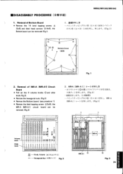
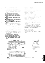
...*R091- L 7i ▪ .-/} . ,is E/7*F)C, (3 x 8) 144cL , -f /1\*C) (4x8) 17#M-1.-, (Fig.1) A A Bottom Cover A A A Fig. 1 2. Removal of MR-A (MR-Al) Circuit Board • Pull out the 9 volume knobs 0 and slide knob. (Fig.2). • Remove the hexagonal nuts. (Fig.2) • Remove the Bottom board. (see procedure 1) • Remove the bind tapping screw © (3x8), the MR-A (MR-Al) circuit...
...*R091- L 7i ▪ .-/} . ,is E/7*F)C, (3 x 8) 144cL , -f /1\*C) (4x8) 17#M-1.-, (Fig.1) A A Bottom Cover A A A Fig. 1 2. Removal of MR-A (MR-Al) Circuit Board • Pull out the 9 volume knobs 0 and slide knob. (Fig.2). • Remove the hexagonal nuts. (Fig.2) • Remove the Bottom board. (see procedure 1) • Remove the bind tapping screw © (3x8), the MR-A (MR-Al) circuit...
Service Manual
Page 18
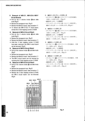
...nuts. (Fig.2) • Remove the Bottom board. (see procedure 1) • Remove the 3 bind tapping screws (G) (3x8), the MR-G circuit board can be removed. (Fig.4) 5. MR-D- 1.0)51•L ' • TI- Removal of MR-E Circuit Board a • Pull out the volume knobs and slide knob. (Fig.2) • ... hexagonal nuts. (Fig.2) • Remove the Bottom board. (see procedure 1) • To remove the MR-C1(C2, F) circuit board, remove the 2 bind tapping screws C)(3x8). 4. Removal of MR-C1, MR-C2 & MR-F Circuit Boards • Pull out the 2 volume knobs C and slide knob. (Fig.2) • ...
...nuts. (Fig.2) • Remove the Bottom board. (see procedure 1) • Remove the 3 bind tapping screws (G) (3x8), the MR-G circuit board can be removed. (Fig.4) 5. MR-D- 1.0)51•L ' • TI- Removal of MR-E Circuit Board a • Pull out the volume knobs and slide knob. (Fig.2) • ... hexagonal nuts. (Fig.2) • Remove the Bottom board. (see procedure 1) • To remove the MR-C1(C2, F) circuit board, remove the 2 bind tapping screws C)(3x8). 4. Removal of MR-C1, MR-C2 & MR-F Circuit Boards • Pull out the 2 volume knobs C and slide knob. (Fig.2) • ...
Service Manual
Page 19
...;0:0.D.!QQ.QQ- Removal of Power Transformer • Remove the Bottom board. (see procedure 1) • Remove the 2 bind head screws (i) (3x12) and 2 bind tapping screws ® (3x8), and then remove the Rear pads. F cfg1.4gLAtz:M-L t (Fig.5) 9. Rear Pad ( 7,:' 7 F.) Fig. 6 (U7, •y 26 l(Fig.6) • Remove the 6 bind tapping screws (:)(3x81, and lift the Rear panel as shown below. (Fig...
...;0:0.D.!QQ.QQ- Removal of Power Transformer • Remove the Bottom board. (see procedure 1) • Remove the 2 bind head screws (i) (3x12) and 2 bind tapping screws ® (3x8), and then remove the Rear pads. F cfg1.4gLAtz:M-L t (Fig.5) 9. Rear Pad ( 7,:' 7 F.) Fig. 6 (U7, •y 26 l(Fig.6) • Remove the 6 bind tapping screws (:)(3x81, and lift the Rear panel as shown below. (Fig...
Service Manual
Page 20
...;Lt-4.-. (1 ,q(4.) • 7, )kiftviyAff4.-)-sy ▪ (Fig.8) 12. MR-L- goo %.,W' 0 00 000 --, --- Removal of MR-L Circuit Boards • Remove the bottom board. (see procedure 1) • Remove the hexagonal nuts retainig jacks, the circuit boards can be removed. (Fig.8) 12. MR842/MR1242/MR1642 11. O , al , CD 0 C),"; © CD © © © © - , - _ 0 © (11, 909_°S)0c...
...;Lt-4.-. (1 ,q(4.) • 7, )kiftviyAff4.-)-sy ▪ (Fig.8) 12. MR-L- goo %.,W' 0 00 000 --, --- Removal of MR-L Circuit Boards • Remove the bottom board. (see procedure 1) • Remove the hexagonal nuts retainig jacks, the circuit boards can be removed. (Fig.8) 12. MR842/MR1242/MR1642 11. O , al , CD 0 C),"; © CD © © © © - , - _ 0 © (11, 909_°S)0c...
Service Manual
Page 21
.../MR1242/MR1642 MR - WI GR 5R 0-.). W2 0- RE WI I WI2 I WI3 I - E GROUP 4 -___ T6 5 P 41_ MR- I T43 WIT • T43 2P W I7 BL WH GR BL (;%4I0 W20 RE POWER SW ' "..7J FUSE WH POWER TRANSFORMER YE BR BR BE BE OR ( RE ) BL OR (RE ) 0 0 • I • I - P1 T4 o (f) o cn 0 IO N N ft) ft) CI' INPUT... W16 BL • W 16 W18 W15 W 15 BL MR- N 114 BE T12 4P 114 3P RE 2 WH T5 9 0 0 WH 02 RE 030A BL ST OUT R PHANTOM MASTER 3 BL BR C RE 1111 1111 T5 MR - B 2/ 2 eo • 3 MR842/MR1242...
.../MR1242/MR1642 MR - WI GR 5R 0-.). W2 0- RE WI I WI2 I WI3 I - E GROUP 4 -___ T6 5 P 41_ MR- I T43 WIT • T43 2P W I7 BL WH GR BL (;%4I0 W20 RE POWER SW ' "..7J FUSE WH POWER TRANSFORMER YE BR BR BE BE OR ( RE ) BL OR (RE ) 0 0 • I • I - P1 T4 o (f) o cn 0 IO N N ft) ft) CI' INPUT... W16 BL • W 16 W18 W15 W 15 BL MR- N 114 BE T12 4P 114 3P RE 2 WH T5 9 0 0 WH 02 RE 030A BL ST OUT R PHANTOM MASTER 3 BL BR C RE 1111 1111 T5 MR - B 2/ 2 eo • 3 MR842/MR1242...


