
Owner's Manual
Page 2
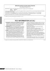
...coloured in your plug proceed as indicated in the instructions contained in FCC Regulations, Part 15 for Class "B" digital devices. The wire which is found in all installation instructions. If these requirements provides a reasonable level of product. Cable/s supplied with the ...Connecting the Plug and Cord IMPORTANT. Modifications not expressly approved by Yamaha may not correspond with the letter L or coloured RED. In the case of this apparatus may void your use this mains lead are on different branch (circuit breaker or fuse) circuits or install AC line...
...coloured in your plug proceed as indicated in the instructions contained in FCC Regulations, Part 15 for Class "B" digital devices. The wire which is found in all installation instructions. If these requirements provides a reasonable level of product. Cable/s supplied with the ...Connecting the Plug and Cord IMPORTANT. Modifications not expressly approved by Yamaha may not correspond with the letter L or coloured RED. In the case of this apparatus may void your use this mains lead are on different branch (circuit breaker or fuse) circuits or install AC line...
Owner's Manual
Page 3
... turn off the power switch, disconnect the electric plug from the outlet, and have the device inspected by qualified Yamaha service personnel. • If this device is easily accessible. Inadequate ventilation can result in an unstable position where it . (5)-4 1/2 MG206C/MG166CX/MG166C Owner's Manual ... generating unwanted noise, make sure there is a sudden loss of sound during the day) to prevent the possibility of panel disfiguration or damage to the product all connected cables. • When setting up the device, make sure to unplug the power cord from the ...
... turn off the power switch, disconnect the electric plug from the outlet, and have the device inspected by qualified Yamaha service personnel. • If this device is easily accessible. Inadequate ventilation can result in an unstable position where it . (5)-4 1/2 MG206C/MG166CX/MG166C Owner's Manual ... generating unwanted noise, make sure there is a sudden loss of sound during the day) to prevent the possibility of panel disfiguration or damage to the product all connected cables. • When setting up the device, make sure to unplug the power cord from the ...
Owner's Manual
Page 4
...; Do not rest your Yamaha dealer. (5)-4 2/2 4 MG206C/MG166CX/MG166C Owner's Manual The main differences between the three models are in ambient temperatures higher than personal use excessive force on the buttons, switches or connectors. Consult qualifi ed Yamaha service personnel about permissible use the device or headphones for a long period of input channels and whether the internal effects are for a long time, make sure you experience any...
...; Do not rest your Yamaha dealer. (5)-4 2/2 4 MG206C/MG166CX/MG166C Owner's Manual The main differences between the three models are in ambient temperatures higher than personal use excessive force on the buttons, switches or connectors. Consult qualifi ed Yamaha service personnel about permissible use the device or headphones for a long period of input channels and whether the internal effects are for a long time, make sure you experience any...
Owner's Manual
Page 5
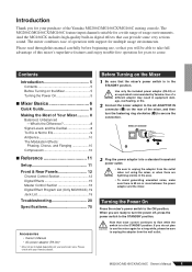
... Power On 5 ■ Mixer Basics 6 Quick Guide 6 Making the Most of Your Mixer........... 8 Balanced, Unbalanced -What's the Difference 8 Signal Levels and the Decibel 8 To EQ or Not to EQ 9 Ambience 10 The Modulation Effects: Phasing, Chorus, and Flanging 10 Compression 10 ■ Reference 11 Setup 11 Front & Rear Panels 12 Channel Control Section 12 Digital Effects 15 Master Control Section 16 Digital Effect Program List (Only MG166CX).19 Jack List 19 Troubleshooting 20 Specifications 75 Accessories • Owner's Manual...
... Power On 5 ■ Mixer Basics 6 Quick Guide 6 Making the Most of Your Mixer........... 8 Balanced, Unbalanced -What's the Difference 8 Signal Levels and the Decibel 8 To EQ or Not to EQ 9 Ambience 10 The Modulation Effects: Phasing, Chorus, and Flanging 10 Compression 10 ■ Reference 11 Setup 11 Front & Rear Panels 12 Channel Control Section 12 Digital Effects 15 Master Control Section 16 Digital Effect Program List (Only MG166CX).19 Jack List 19 Troubleshooting 20 Specifications 75 Accessories • Owner's Manual...
Owner's Manual
Page 6
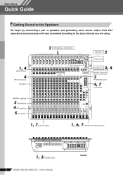
Note that operations and procedures will vary somewhat according to the Speakers We begin by connecting a pair of speakers and generating some stereo output. Mixer Basics Quick Guide Mixer Basics Getting Sound to the input devices you are using. 1, 4 GAIN controls 4 PEAK indicators Equalizer 2 Microphones, instruments 2 Speakers Power Amp 2, 4 Headphones Monitor Speakers 3 PHANTOM switch 4, 7 Level meter PAN/BAL switches 5 ON switches 4 PFL switches 5 ST switches 1, 7 Channel faders 1, 6, 7 STEREO OUT Master fader 1, 3 POWER switch 6 MG206C/MG166CX/MG166C Owner's Manual MG206C
Note that operations and procedures will vary somewhat according to the Speakers We begin by connecting a pair of speakers and generating some stereo output. Mixer Basics Quick Guide Mixer Basics Getting Sound to the input devices you are using. 1, 4 GAIN controls 4 PEAK indicators Equalizer 2 Microphones, instruments 2 Speakers Power Amp 2, 4 Headphones Monitor Speakers 3 PHANTOM switch 4, 7 Level meter PAN/BAL switches 5 ON switches 4 PFL switches 5 ST switches 1, 7 Channel faders 1, 6, 7 STEREO OUT Master fader 1, 3 POWER switch 6 MG206C/MG166CX/MG166C Owner's Manual MG206C
Owner's Manual
Page 7
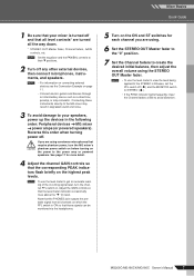
... power amp or powered speakers. See page 17 for each channel you are turned all channels on the power to your mixer is ON so that those signals can be monitored via the headphones. 5 Turn on the ON and ST switches for more detail. 4 Adjust the channel GAIN controls so that the PHONES jack outputs the prefader signal from all the way down. * STEREO OUT Master fader, Channel faders, GAIN controls, etc. Adjust the GAIN controls so that all level controls* are using the STEREO...
... power amp or powered speakers. See page 17 for each channel you are turned all channels on the power to your mixer is ON so that those signals can be monitored via the headphones. 5 Turn on the ON and ST switches for more detail. 4 Adjust the channel GAIN controls so that the PHONES jack outputs the prefader signal from all the way down. * STEREO OUT Master fader, Channel faders, GAIN controls, etc. Adjust the GAIN controls so that all level controls* are using the STEREO...
Owner's Manual
Page 8
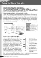
...'re very good at one million) times louder. Balanced noise cancellation Noise Phase inversion Hot (+) Cold (-) Ground Source Cable Phase inversion Noise cancelled Receiving device Noise-free signal To summarize Microphones Use balanced lines. Average speech is about -30 dBu, but if this is the first time you've ever used a mixer you might be heard is necessary match input and output levels as closely as 0 dBu. The whole...
...'re very good at one million) times louder. Balanced noise cancellation Noise Phase inversion Hot (+) Cold (-) Ground Source Cable Phase inversion Noise cancelled Receiving device Noise-free signal To summarize Microphones Use balanced lines. Average speech is about -30 dBu, but if this is the first time you've ever used a mixer you might be heard is necessary match input and output levels as closely as 0 dBu. The whole...
Owner's Manual
Page 10
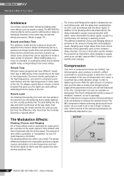
... Different reverb programs will depend on the music's tempo and density, but as an outright "special effect" to page 15). The amount of time shift is primarily in order to create a wide variety of these effects work on bass guitar. OUTPUT (Min) (Max) INPUT 10 MG206C/MG166CX/MG166C Owner's Manual Compression One form of delay time and feedback used , produce a smooth, unified sound with the direct signal...
... Different reverb programs will depend on the music's tempo and density, but as an outright "special effect" to page 15). The amount of time shift is primarily in order to create a wide variety of these effects work on bass guitar. OUTPUT (Min) (Max) INPUT 10 MG206C/MG166CX/MG166C Owner's Manual Compression One form of delay time and feedback used , produce a smooth, unified sound with the direct signal...
Owner's Manual
Page 13
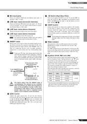
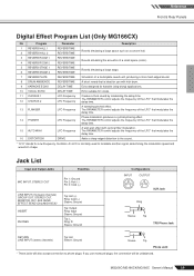
... sound cancellation. 6 GAIN Control Adjusts the input signal level. To the input jack of the external processor To the INSERT I/O jack Tip: OUT Sleeve (Ground) Ring: IN Tip: OUT Tip: IN To the output jack of the external processor CAUTION The signal output from 250 Hz to the line inputs of stereo input channels 3, 4). 8 COMP Control Adjusts the amount of device. S: Ground). The INSERT jacks are attenuated while the overall level is the LINE input adjustment range. 7 Switch (High-Pass Filter) This switch...
... sound cancellation. 6 GAIN Control Adjusts the input signal level. To the input jack of the external processor To the INSERT I/O jack Tip: OUT Sleeve (Ground) Ring: IN Tip: OUT Tip: IN To the output jack of the external processor CAUTION The signal output from 250 Hz to the line inputs of stereo input channels 3, 4). 8 COMP Control Adjusts the amount of device. S: Ground). The INSERT jacks are attenuated while the overall level is the LINE input adjustment range. 7 Switch (High-Pass Filter) This switch...
Owner's Manual
Page 14
... by the AUX PRE switch B) EFFECT: Post-fader • MG166C AUX1: Pre-fader AUX2: Pre-fader/post-fader (determines by the channel fader I Channel Fader Adjusts the level of the channel signal. G 3-4 Switch This switch assigns the channel's signal to minimize noise. 14 MG206C/MG166CX/MG166C Owner's Manual NOTE Set the fader sliders for monitoring. The types of signals sent by the AUX and EFFECT controls on ( ). These controls send either the signal from the channel to the GROUP 1/2 bus turn the ON switch on ( ), the mixer sends the pre-fader signal to adjust the balance...
... by the AUX PRE switch B) EFFECT: Post-fader • MG166C AUX1: Pre-fader AUX2: Pre-fader/post-fader (determines by the channel fader I Channel Fader Adjusts the level of the channel signal. G 3-4 Switch This switch assigns the channel's signal to minimize noise. 14 MG206C/MG166CX/MG166C Owner's Manual NOTE Set the fader sliders for monitoring. The types of signals sent by the AUX and EFFECT controls on ( ). These controls send either the signal from the channel to the GROUP 1/2 bus turn the ON switch on ( ), the mixer sends the pre-fader signal to adjust the balance...
Owner's Manual
Page 15
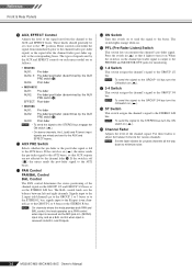
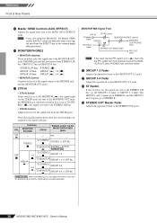
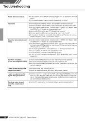
...STEREO bus. MG206C/MG166CX/MG166C Owner's Manual 15 Reference Front & Rear Panels Digital Effects 1 2 3 4 5 6 0 * Only the MG166CX has digital effects. 1 FOOT SWITCH Jack A Yamaha FC5 foot switch (sold separately) can be used to toggle the digital effects ON and OFF. 7 NOTE The ON switch lights and the internal effect unit is active when the 8 power is initially turned on. 9 6 PFL Switch Turn this switch on to send the effect signal to the PFL bus. 7 1-2 Switch This switch assigns the effect signal to the GROUP 1/2 bus. 8 3-4 Switch This switch assigns the effect signal...
...STEREO bus. MG206C/MG166CX/MG166C Owner's Manual 15 Reference Front & Rear Panels Digital Effects 1 2 3 4 5 6 0 * Only the MG166CX has digital effects. 1 FOOT SWITCH Jack A Yamaha FC5 foot switch (sold separately) can be used to toggle the digital effects ON and OFF. 7 NOTE The ON switch lights and the internal effect unit is active when the 8 power is initially turned on. 9 6 PFL Switch Turn this switch on to send the effect signal to the PFL bus. 7 1-2 Switch This switch assigns the effect signal to the GROUP 1/2 bus. 8 3-4 Switch This switch assigns the effect signal...
Owner's Manual
Page 17
... output jacks. The PEAK indicator lights red when the output reaches the clipping level. The pre-fader send option should be used to the phantom power supply. effects units). Use these jacks to connect to the input jacks of headphones to external signal processors (e.g. NOTE The signal output by these jacks. CAUTION • When turning the switch on the signal output via the RETURN2 jacks are adjusted using the STEREO OUT Master fader I for level control. • XLR jacks XLR-type balanced output jacks. • LINE jacks TRS phone-type balanced output jacks. 7 MONITOR...
... output jacks. The PEAK indicator lights red when the output reaches the clipping level. The pre-fader send option should be used to the phantom power supply. effects units). Use these jacks to connect to the input jacks of headphones to external signal processors (e.g. NOTE The signal output by these jacks. CAUTION • When turning the switch on the signal output via the RETURN2 jacks are adjusted using the STEREO OUT Master fader I for level control. • XLR jacks XLR-type balanced output jacks. • LINE jacks TRS phone-type balanced output jacks. 7 MONITOR...
Owner's Manual
Page 18
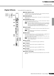
...Master SEND control (EFFECT) does not affect the level of the mon- itor playback signal and the signal being recorded separately. Reference Front & Rear Panels C Master SEND Controls (AUX, EFFECT) Adjusts the signal level sent to STEREO R. The GROUP 1 and 3 signals go to STEREO L and the GROUP 2 and 4 signals go to the SEND (AUX, EFFECT) jacks. MONITOR MIX Signal Flow 2TR IN 2TR IN control Playback signal Recording STEREO bus MONITOR/PHONES controls MONITOR OUT/PHONES jacks signal STEREO OUT Master fader REC OUT jacks NOTE If the input channel PFL switch...
...Master SEND control (EFFECT) does not affect the level of the mon- itor playback signal and the signal being recorded separately. Reference Front & Rear Panels C Master SEND Controls (AUX, EFFECT) Adjusts the signal level sent to STEREO R. The GROUP 1 and 3 signals go to STEREO L and the GROUP 2 and 4 signals go to the SEND (AUX, EFFECT) jacks. MONITOR MIX Signal Flow 2TR IN 2TR IN control Playback signal Recording STEREO bus MONITOR/PHONES controls MONITOR OUT/PHONES jacks signal STEREO OUT Master fader REC OUT jacks NOTE If the input channel PFL switch...
Owner's Manual
Page 19
...;lter modulation. A short reverb that modulates the delay time. Creates a thick sound by modulating the delay time. The PARAMETER control adjusts the frequency of the LFO* that is normally used to the sound. * "LFO" stands for use monaural plugs, the connection will also accept connection to phone plugs. Jack List Input and Output Jacks Polarities MIC INPUT, STEREO OUT Pin 1: Ground Pin 2: Hot (+) Pin 3: Cold (-) LINE INPUT (monaural channels) GROUP OUT, STEREO OUT, MONITOR OUT, AUX SEND, EFFECT SEND (Only MG166CX)* INSERT PHONES Tip: Hot...
...;lter modulation. A short reverb that modulates the delay time. Creates a thick sound by modulating the delay time. The PARAMETER control adjusts the frequency of the LFO* that is normally used to the sound. * "LFO" stands for use monaural plugs, the connection will also accept connection to phone plugs. Jack List Input and Output Jacks Polarities MIC INPUT, STEREO OUT Pin 1: Ground Pin 2: Hot (+) Pin 3: Cold (-) LINE INPUT (monaural channels) GROUP OUT, STEREO OUT, MONITOR OUT, AUX SEND, EFFECT SEND (Only MG166CX)* INSERT PHONES Tip: Hot...
Owner's Manual
Page 20
... speaker cables connected properly, or are using MG166CX) ❑ Check that the EFFECT PARAMETER control and EFFECT RTN fader are correctly adjusted. Reference Troubleshooting Power doesn't come on each channel. Please connect to the MIC input jacks? ❑ If you are ON. ❑ Adjust the equalizers (HIGH, MID and LOW) on ? 20 MG206C/MG166CX/MG166C Owner's Manual No sound. ❑ Are microphones, external devices, and speakers connected correctly? ❑ Are the ON switch and ST switch of service centers.) Sound is turned...
... speaker cables connected properly, or are using MG166CX) ❑ Check that the EFFECT PARAMETER control and EFFECT RTN fader are correctly adjusted. Reference Troubleshooting Power doesn't come on each channel. Please connect to the MIC input jacks? ❑ If you are ON. ❑ Adjust the equalizers (HIGH, MID and LOW) on ? 20 MG206C/MG166CX/MG166C Owner's Manual No sound. ❑ Are microphones, external devices, and speakers connected correctly? ❑ Are the ON switch and ST switch of service centers.) Sound is turned...
Owner's Manual
Page 21
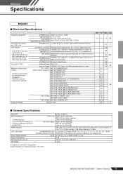
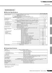
...) LOW: 100 Hz (shelving) Red LED turns on when post EQ signal (either post MIC HA or post EQ signal for CHs 13/14-19/20) reaches -3 dB below the clipping level. AUX SEND Master/AUX control at nominal level and all CH AUX controls at GROUP OUT nominal level and all channels' ST and 1-2, 3-4 switches off frequency of signal generator: 150 ohms MG206C/MG166CX/MG166C Owner's Manual 75 STEREO OUT STEREO OUT, GROUP 1-2, GROUP 3-4 faders and...
...) LOW: 100 Hz (shelving) Red LED turns on when post EQ signal (either post MIC HA or post EQ signal for CHs 13/14-19/20) reaches -3 dB below the clipping level. AUX SEND Master/AUX control at nominal level and all CH AUX controls at GROUP OUT nominal level and all channels' ST and 1-2, 3-4 switches off frequency of signal generator: 150 ohms MG206C/MG166CX/MG166C Owner's Manual 75 STEREO OUT STEREO OUT, GROUP 1-2, GROUP 3-4 faders and...
Owner's Manual
Page 22
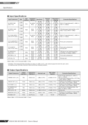
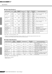
... output level when the unit is set to the maximum level. (All faders and level controls are at their maximum position.) ■ Output Specifications Output Connectors Output Impedance Appropriate Impedance STEREO OUT (L, R) 75Ω 600Ω Lines GROUP OUT (1-4) 150Ω 10kΩ Lines AUX SEND (1-4) 150Ω 10kΩ Lines CH INSERT OUT (CHs 1-12) REC OUT (L, R) 75Ω 600Ω 10kΩ Lines 10kΩ Lines MONITOR...
... output level when the unit is set to the maximum level. (All faders and level controls are at their maximum position.) ■ Output Specifications Output Connectors Output Impedance Appropriate Impedance STEREO OUT (L, R) 75Ω 600Ω Lines GROUP OUT (1-4) 150Ω 10kΩ Lines AUX SEND (1-4) 150Ω 10kΩ Lines CH INSERT OUT (CHs 1-12) REC OUT (L, R) 75Ω 600Ω 10kΩ Lines 10kΩ Lines MONITOR...
Owner's Manual
Page 23
... dB) STEREO/GROUP/PFL bus PEAK lights if the signal level reaches 3 dB below the clipping level. Crosstalk (1 kHz) Maximum voltage gain (1 kHz) All faders and controls are measured with infinite dB/octave attenuation. EFFECT/AUX* SEND Master EFFECT/AUX* control at nominal level and all channels' ST and 1-2, 3-4 switches off frequency of signal generator: 150 ohms * MG166CX: AUX1, 2, EFFECT MG166C: AUX1, 2, 3 MG206C/MG166CX/MG166C Owner's Manual 77 STEREO OUT Residual Output Noise Adjacent Input CHs 1-8 Input to Output STEREO L/R, CHs...
... dB) STEREO/GROUP/PFL bus PEAK lights if the signal level reaches 3 dB below the clipping level. Crosstalk (1 kHz) Maximum voltage gain (1 kHz) All faders and controls are measured with infinite dB/octave attenuation. EFFECT/AUX* SEND Master EFFECT/AUX* control at nominal level and all channels' ST and 1-2, 3-4 switches off frequency of signal generator: 150 ohms * MG166CX: AUX1, 2, EFFECT MG166C: AUX1, 2, 3 MG206C/MG166CX/MG166C Owner's Manual 77 STEREO OUT Residual Output Noise Adjacent Input CHs 1-8 Input to Output STEREO L/R, CHs...
Owner's Manual
Page 24
... nominal output level when the unit is set to the maximum level. (All faders and level controls are at their maximum position.) ■ Output Specifications Output Connectors Output Impedance Appropriate Impedance STEREO OUT (L, R) 75Ω 600Ω Lines GROUP OUT (1-4) 150Ω 10kΩ Lines EFFECT/AUX* SEND 150Ω 10kΩ Lines CH INSERT OUT (CHs 1-8) REC OUT (L, R) 75Ω 600Ω 10kΩ Lines 10kΩ Lines MONITOR...
... nominal output level when the unit is set to the maximum level. (All faders and level controls are at their maximum position.) ■ Output Specifications Output Connectors Output Impedance Appropriate Impedance STEREO OUT (L, R) 75Ω 600Ω Lines GROUP OUT (1-4) 150Ω 10kΩ Lines EFFECT/AUX* SEND 150Ω 10kΩ Lines CH INSERT OUT (CHs 1-8) REC OUT (L, R) 75Ω 600Ω 10kΩ Lines 10kΩ Lines MONITOR...
Owner's Manual
Page 27
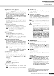
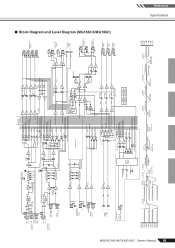
... DR LED Meter MONI/PHONES INV [-16dBu] INV SUM SUM SUM AUX SEND 1 [0dBu] [-6dBu] BA AUX SEND 2 [0dBu] [-6dBu] BA [0dBu] AUX SEND* [-6dBu] BA MONITOR MIX MODEL MG166C MG166CX AUX * AUX 3 EFFECT 1 2 GROUP OUT [+4dBu] 3 4 L STEREO OUT [+4dBu] R L REC OUT [-10dBV] R [-7.8dBu] L MONITOR OUT [+4dBu] R PHONES [3mW,40ohms] AUX SEND 1 [+4dBu] AUX SEND 2 [+4dBu] AUX SEND * [+4dBu] [-6dBu] Clip Level Clip Level Clip Level Clip Level AUX SEND *1 [+4dBu] GROUP OUT [+4dBu] AUX SEND *1 [Nominal:-6dB] GROUP Fader [Nominal:-10dB] ST Master [Nominal...
... DR LED Meter MONI/PHONES INV [-16dBu] INV SUM SUM SUM AUX SEND 1 [0dBu] [-6dBu] BA AUX SEND 2 [0dBu] [-6dBu] BA [0dBu] AUX SEND* [-6dBu] BA MONITOR MIX MODEL MG166C MG166CX AUX * AUX 3 EFFECT 1 2 GROUP OUT [+4dBu] 3 4 L STEREO OUT [+4dBu] R L REC OUT [-10dBV] R [-7.8dBu] L MONITOR OUT [+4dBu] R PHONES [3mW,40ohms] AUX SEND 1 [+4dBu] AUX SEND 2 [+4dBu] AUX SEND * [+4dBu] [-6dBu] Clip Level Clip Level Clip Level Clip Level AUX SEND *1 [+4dBu] GROUP OUT [+4dBu] AUX SEND *1 [Nominal:-6dB] GROUP Fader [Nominal:-10dB] ST Master [Nominal...


