
Owner's Manual
Page 2
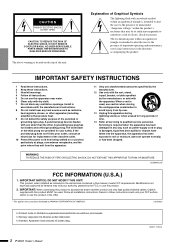
... for replacement of the obsolete outlet. 10 Protect the power cord from being walked on the top of time. 14 Refer all installation instructions. When a cart is used . IMPORTANT NOTICE: DO NOT MODIFY THIS UNIT! Cable/s supplied with arrowhead symbol within an equilateral triangle is intended to alert the user to the presence of the polarized or grounding-type plug. Failure...
... for replacement of the obsolete outlet. 10 Protect the power cord from being walked on the top of time. 14 Refer all installation instructions. When a cart is used . IMPORTANT NOTICE: DO NOT MODIFY THIS UNIT! Cable/s supplied with arrowhead symbol within an equilateral triangle is intended to alert the user to the presence of the polarized or grounding-type plug. Failure...
Owner's Manual
Page 3
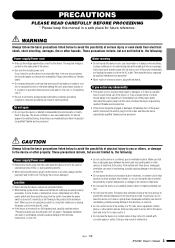
... a protective grounding connection. Location • Before moving the device, remove all connected cables. • When setting up the device, make sure to it. • Do not place the device in a location where it , immediately turn off the power switch, disconnect the electric plug from the outlet, and have the device inspected by qualified Yamaha service personnel. • If this manual...
... a protective grounding connection. Location • Before moving the device, remove all connected cables. • When setting up the device, make sure to it. • Do not place the device in a location where it , immediately turn off the power switch, disconnect the electric plug from the outlet, and have the device inspected by qualified Yamaha service personnel. • If this manual...
Owner's Manual
Page 4
... the device inspected by improper use only the speaker cables for connecting speakers to the speaker jacks. Always turn the power off when the device is lost or destroyed. Ltd. (3 wires) 4 IPA8200 Owner's Manual (5)-6 2/2 When turning the power off, the device should be held responsible for damage caused by qualified Yamaha service personnel. • Do not use speakers for a long period of time at any purpose other devices...
... the device inspected by improper use only the speaker cables for connecting speakers to the speaker jacks. Always turn the power off when the device is lost or destroyed. Ltd. (3 wires) 4 IPA8200 Owner's Manual (5)-6 2/2 When turning the power off, the device should be held responsible for damage caused by qualified Yamaha service personnel. • Do not use speakers for a long period of time at any purpose other devices...
Owner's Manual
Page 5
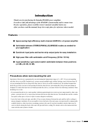
... a safe place for reference when needed for your application ■ Euroblock input jacks and barrier strip output jacks for easy installation ■ High-pass filter with switchable cutoff frequency (20 Hz / 55 Hz) ■ Input sensitivity / gain select switch switchable between STEREO/PARALLEL/BRIDGE modes as needed . If you have installed a fan kit, there may be cases in this space or...
... a safe place for reference when needed for your application ■ Euroblock input jacks and barrier strip output jacks for easy installation ■ High-pass filter with switchable cutoff frequency (20 Hz / 55 Hz) ■ Input sensitivity / gain select switch switchable between STEREO/PARALLEL/BRIDGE modes as needed . If you have installed a fan kit, there may be cases in this space or...
Owner's Manual
Page 6
... ...5 Precautions when rack-mounting the unit 5 Controls and Functions 7 Front Panel ...7 Rear Panel...8 Mode settings ...9 STEREO mode...9 PARALLEL mode 9 BRIDGE mode...9 Connections ...10 Input jack connections (Euroblock 10 Speaker connections (barrier strip 10 Troubleshooting 11 Specifications ...57 General Specifications 57 Block Diagram 58 Dimensions...58 Current Draw ...59 Accessories (Please make sure the following items are included in the package.) • IPA8200 Owner's Manual (this document) • Power cable (2.5 m) x 1 • Security cover x 1 • Allen wrench...
... ...5 Precautions when rack-mounting the unit 5 Controls and Functions 7 Front Panel ...7 Rear Panel...8 Mode settings ...9 STEREO mode...9 PARALLEL mode 9 BRIDGE mode...9 Connections ...10 Input jack connections (Euroblock 10 Speaker connections (barrier strip 10 Troubleshooting 11 Specifications ...57 General Specifications 57 Block Diagram 58 Dimensions...58 Current Draw ...59 Accessories (Please make sure the following items are included in the package.) • IPA8200 Owner's Manual (this document) • Power cable (2.5 m) x 1 • Security cover x 1 • Allen wrench...
Owner's Manual
Page 7
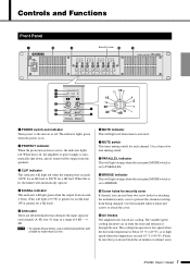
... rear panel MODE switch is automatically shut down, and no wider than 5.5 mm. The variable speed cooling fan draws air in a range of each channel. Please be output from the speakers. The indicator lights green when the power is set to BRIDGE. !0 Screw holes for a 4Ω load.) t Attenuator These are detented knobs that you can use these knobs, use a slotted screwdriver with a blade no sound...
... rear panel MODE switch is automatically shut down, and no wider than 5.5 mm. The variable speed cooling fan draws air in a range of each channel. Please be output from the speakers. The indicator lights green when the power is set to BRIDGE. !0 Screw holes for a 4Ω load.) t Attenuator These are detented knobs that you can use these knobs, use a slotted screwdriver with a blade no sound...
Owner's Manual
Page 8
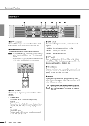
... frequency will be used . 8 IPA8200 Owner's Manual Connect the plug end of the AC power cable to an AC outlet of the correct voltage. • If this is to be rack mounted and transported frequently, be cut by a 12 dB/oct. filter. NOTE • If using BRIDGE mode, connect the speakers to support the rear end of the barrier strip connectors. Controls and Functions Rear Panel q ew r ty u q INPUT...
... frequency will be used . 8 IPA8200 Owner's Manual Connect the plug end of the AC power cable to an AC outlet of the correct voltage. • If this is to be rack mounted and transported frequently, be cut by a 12 dB/oct. filter. NOTE • If using BRIDGE mode, connect the speakers to support the rear end of the barrier strip connectors. Controls and Functions Rear Panel q ew r ty u q INPUT...
Owner's Manual
Page 9
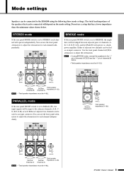
...used as an input connector. IPA8200 Owner's Manual 9 Do not use a setup that can be connected will depend on the mode setting. Either of channels (AB, C-D, E-F, G-H), and the IPA8200 will be 8-16Ω. Use the front panel channel A/C/E/G attenuators to adjust the attenuation. Source: Channel A Total speaker impedance: 8-16Ω Source: Channel A Total speaker Source: impedance: 4-8Ω Channel A NOTE • Total speaker impedance must be 4-8Ω. STEREO mode If the rear panel MODE switch is set to BRIDGE, the amplifiers will operate independently. Source...
...used as an input connector. IPA8200 Owner's Manual 9 Do not use a setup that can be connected will depend on the mode setting. Either of channels (AB, C-D, E-F, G-H), and the IPA8200 will be 8-16Ω. Use the front panel channel A/C/E/G attenuators to adjust the attenuation. Source: Channel A Total speaker impedance: 8-16Ω Source: Channel A Total speaker Source: impedance: 4-8Ω Channel A NOTE • Total speaker impedance must be 4-8Ω. STEREO mode If the rear panel MODE switch is set to BRIDGE, the amplifiers will operate independently. Source...
Owner's Manual
Page 10
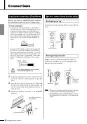
... IPA8200's input jack. Euroblock connector Wires -G + 10 IPA8200 Owner's Manual If you lose them, contact your equipment, use a lacing bar when possible to bundle and fasten the cables. nector, strip the wire as the AI0, 5-6WH made by the Phoenix Contact corporation). 1.6 mm approx. approx. 7 mm Speaker connections (barrier strip) If using BRIDGE mode, connect the speakers to the "+" pin of channels A/C/E/G and the "-" pin of a portable installation...
... IPA8200's input jack. Euroblock connector Wires -G + 10 IPA8200 Owner's Manual If you lose them, contact your equipment, use a lacing bar when possible to bundle and fasten the cables. nector, strip the wire as the AI0, 5-6WH made by the Phoenix Contact corporation). 1.6 mm approx. approx. 7 mm Speaker connections (barrier strip) If using BRIDGE mode, connect the speakers to the "+" pin of channels A/C/E/G and the "-" pin of a portable installation...
Owner's Manual
Page 11
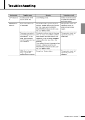
... unit. Possible cause Output exceeds 100 W (8Ω) or 200 W (4Ω). If the PROTECT indicator is shorted. Check whether the speaker output connector or speaker cable could be blockage at the air intake or a ventilation problem inside the rack, and verify that the load impedance of the connected speakers is Consult your Yamaha dealer. Speaker output connector is still lit, contact your Yamaha dealer. IPA8200 Owner's Manual 11
... unit. Possible cause Output exceeds 100 W (8Ω) or 200 W (4Ω). If the PROTECT indicator is shorted. Check whether the speaker output connector or speaker cable could be blockage at the air intake or a ventilation problem inside the rack, and verify that the load impedance of the connected speakers is Consult your Yamaha dealer. Speaker output connector is still lit, contact your Yamaha dealer. IPA8200 Owner's Manual 11
Owner's Manual
Page 12
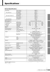
... Input Level Input Impedance Input Sensitivity (dBu) 8Ω, Att. Max S/N Ratio THD+N Frequency Response Channel Separation Controls 4Ω per channel 8Ω per channel 8Ω / BRIDGE 4Ω per channel 8Ω per channel 8Ω / BRIDGE 4Ω per channel 8Ω per channel 8Ω / BRIDGE Switch Position Input sensitivity Switch Position Voltage Gain A-weighted 1kHz, half power, 4Ω 1W, 8Ω 1kHz, half power, 8Ω Att. max, input 600Ω shunt Front Panel Rear Panel Connectors Indicators Input Output Power Load Protection...
... Input Level Input Impedance Input Sensitivity (dBu) 8Ω, Att. Max S/N Ratio THD+N Frequency Response Channel Separation Controls 4Ω per channel 8Ω per channel 8Ω / BRIDGE 4Ω per channel 8Ω per channel 8Ω / BRIDGE 4Ω per channel 8Ω per channel 8Ω / BRIDGE Switch Position Input sensitivity Switch Position Voltage Gain A-weighted 1kHz, half power, 4Ω 1W, 8Ω 1kHz, half power, 8Ω Att. max, input 600Ω shunt Front Panel Rear Panel Connectors Indicators Input Output Power Load Protection...
Owner's Manual
Page 13
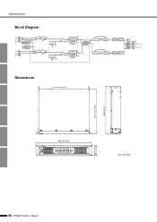
BA Clip Level Detect P.Amp Signal Level Detect Comp. BA Level Detect Inv P.Amp Signal Level Detect Output Filter SPEAKERS - + A, C, E, G - + B, D, F, H Dimensions 377.7 (14-7/8") 406.5 (16") 480 (18-7/8") 88 (3-7/16") Unit: mm (inch) 58 IPA8200 Owner's Manual HA G GAIN GAIN CH B, D, F, H HPF HPF Fc=20Hz HPF Fc=55Hz HPF Fc=20Hz HPF Fc=55Hz HPF STEREO MODE BRIDGE PARALLEL Comp. G STEREO MODE BRIDGE ATTENUATOR MUTE HA PARALLEL STEREO BRIDGE PARALLEL + ATTENUATOR MUTE - Specifications Block Diagram CH A, C, E, G + -
BA Clip Level Detect P.Amp Signal Level Detect Comp. BA Level Detect Inv P.Amp Signal Level Detect Output Filter SPEAKERS - + A, C, E, G - + B, D, F, H Dimensions 377.7 (14-7/8") 406.5 (16") 480 (18-7/8") 88 (3-7/16") Unit: mm (inch) 58 IPA8200 Owner's Manual HA G GAIN GAIN CH B, D, F, H HPF HPF Fc=20Hz HPF Fc=55Hz HPF Fc=20Hz HPF Fc=55Hz HPF STEREO MODE BRIDGE PARALLEL Comp. G STEREO MODE BRIDGE ATTENUATOR MUTE HA PARALLEL STEREO BRIDGE PARALLEL + ATTENUATOR MUTE - Specifications Block Diagram CH A, C, E, G + -
Owner's Manual
Page 14
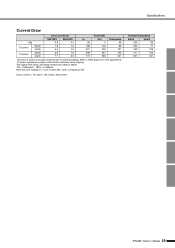
... 77 433 109 417 105 821 207 IPA8200 Owner's Manual 59 Test signal: Pink Noise, bandwidth limited from 22Hz to 22kHz 1W = 0.860kcal/h, 1BTU = 0.252kcal Note that Line Voltage [V] x Line Current [A] = [VA], not equals to these figures for most applications. 1/3 power represents program material with occasional clipping. Specifications Current Draw Line Current (A) Power (W) 100/120V 230/240V In Out...
... 77 433 109 417 105 821 207 IPA8200 Owner's Manual 59 Test signal: Pink Noise, bandwidth limited from 22Hz to 22kHz 1W = 0.860kcal/h, 1BTU = 0.252kcal Note that Line Voltage [V] x Line Current [A] = [VA], not equals to these figures for most applications. 1/3 power represents program material with occasional clipping. Specifications Current Draw Line Current (A) Power (W) 100/120V 230/240V In Out...
Owner's Manual
Page 18
... Nakazawa-cho 10-1, Naka-ku, Hamamatsu, Japan 430-8650 Tel: +81-53-460-2313 PA24 HEAD OFFICE Yamaha Corporation, Pro Audio & Digital Musical Instrument Division Nakazawa-cho 10-1, Naka-ku, Hamamatsu, Japan 430-8650 Tel: +81-53-460-2441 IPA8200 Owner's Manual 63 A. Torre Banco General, Piso 7, Urbanización Marbella, Calle 47 y Aquilino de la Guardia, Ciudad de...
... Nakazawa-cho 10-1, Naka-ku, Hamamatsu, Japan 430-8650 Tel: +81-53-460-2313 PA24 HEAD OFFICE Yamaha Corporation, Pro Audio & Digital Musical Instrument Division Nakazawa-cho 10-1, Naka-ku, Hamamatsu, Japan 430-8650 Tel: +81-53-460-2441 IPA8200 Owner's Manual 63 A. Torre Banco General, Piso 7, Urbanización Marbella, Calle 47 y Aquilino de la Guardia, Ciudad de...


