
Owner's Manual
Page 2
... found in the users manual, may cause undesired operation. Failure to follow instructions could void your use of Equipment : MIXING CONSOLE Model Name : IM8-40/IM8-32/IM8-24 This device complies with these corrective measures do not produce satisfactory results, please contact the local retailer authorized to products distributed by YAMAHA CORPORATION OF AMERICA. Compliance...
... found in the users manual, may cause undesired operation. Failure to follow instructions could void your use of Equipment : MIXING CONSOLE Model Name : IM8-40/IM8-32/IM8-24 This device complies with these corrective measures do not produce satisfactory results, please contact the local retailer authorized to products distributed by YAMAHA CORPORATION OF AMERICA. Compliance...
Owner's Manual
Page 4
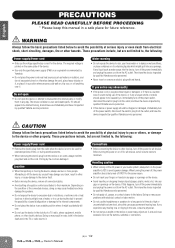
...ngers or hands in a safe place for all equalizer controls and faders to be caused by it inspected by qualified Yamaha service personnel. CAUTION Always follow the basic precautions listed below to avoid the possibility of the connected devices, doing so may cause .... Connections • Before connecting the device to the device or other devices, turn on the buttons, switches or connectors. (5)-5 1/2 4 Owner's Manual If you or others, or damage to other property. Depending on or off the power for future reference. Before turning the power on the condition...
...ngers or hands in a safe place for all equalizer controls and faders to be caused by it inspected by qualified Yamaha service personnel. CAUTION Always follow the basic precautions listed below to avoid the possibility of the connected devices, doing so may cause .... Connections • Before connecting the device to the device or other devices, turn on the buttons, switches or connectors. (5)-5 1/2 4 Owner's Manual If you or others, or damage to other property. Depending on or off the power for future reference. Before turning the power on the condition...
Owner's Manual
Page 5
...is strictly prohibited except for information purposes only. Insert TRS phone jacks are for your Yamaha dealer. (5)-5 2/2 Owner's Manual 5 SPECIAL NOTICES • This manual is the exclusive copyright of Yamaha Corporation. • The software included in part by improper use or modifications...announced separately. European models Purchaser/User Information specified in this manual are for use with moving contacts, such as follows: sleeve: ground, tip: send, and ring: return. Yamaha cannot be held responsible for damage caused by any time without limitation, ...
...is strictly prohibited except for information purposes only. Insert TRS phone jacks are for your Yamaha dealer. (5)-5 2/2 Owner's Manual 5 SPECIAL NOTICES • This manual is the exclusive copyright of Yamaha Corporation. • The software included in part by improper use or modifications...announced separately. European models Purchaser/User Information specified in this manual are for use with moving contacts, such as follows: sleeve: ground, tip: send, and ring: return. Yamaha cannot be held responsible for damage caused by any time without limitation, ...
Owner's Manual
Page 6
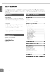
... Power supply cable • Cubase AI 4 DVD-ROM • USB cable Introduction 6 Features 6 Accessories 6 System Requirements 7 Differences between the IM8-40/32/24 mixers 7 Controls and Functions 8 Channel Control Section 8 Master Control Section 12 STEREO AUX RETURN Section 13 2TR IN/USB Section 13 ...and Level Diagram..174 6 Owner's Manual Using just a single knob, you can accommodate line-level devices. • Compressors A compressor is provided on the AUX sends, allowing you to use , so that can compress the peaks of the Yamaha IM8 mixing console. After you've ...
... Power supply cable • Cubase AI 4 DVD-ROM • USB cable Introduction 6 Features 6 Accessories 6 System Requirements 7 Differences between the IM8-40/32/24 mixers 7 Controls and Functions 8 Channel Control Section 8 Master Control Section 12 STEREO AUX RETURN Section 13 2TR IN/USB Section 13 ...and Level Diagram..174 6 Owner's Manual Using just a single knob, you can accommodate line-level devices. • Compressors A compressor is provided on the AUX sends, allowing you to use , so that can compress the peaks of the Yamaha IM8 mixing console. After you've ...

Owner's Manual
Page 7
...models. • Number of LAMP connectors The IM8-40 provides three LAMP connectors to which differ as follows. • Number of monaural input channels The IM8-40 provides 40 monaural input channels, the IM832 provides 32, and the IM8-24 provides 24. English Introduction System Requirements ■...AI, check the web site below. Owner's Manual 7 Differences between the IM8-40/32/24 mixers The IM8 mixer is available in three models (IM8-40, IM8-32, IM8-24) which you can connect separately sold gooseneck lamps (e.g., Yamaha LA5000), while the IM8-32 and IM8-24 provide two such connectors.
...models. • Number of LAMP connectors The IM8-40 provides three LAMP connectors to which differ as follows. • Number of monaural input channels The IM8-40 provides 40 monaural input channels, the IM832 provides 32, and the IM8-24 provides 24. English Introduction System Requirements ■...AI, check the web site below. Owner's Manual 7 Differences between the IM8-40/32/24 mixers The IM8 mixer is available in three models (IM8-40, IM8-32, IM8-24) which you can connect separately sold gooseneck lamps (e.g., Yamaha LA5000), while the IM8-32 and IM8-24 provide two such connectors.
Owner's Manual
Page 8
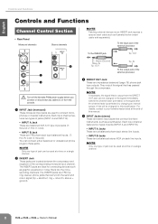
...IN Tip: OUT Tip: IN To the output jack of the external processor To the INSERT jack Tip: OUT 1 4 2 3 Turn off the Yamaha PW8 power supply before the channel fader (pre-fader) or the signal after the channel fader (post-fader) by changing an internal jumper. S: Ground...) You can be used to your Yamaha dealer listed at a time on a single channel. 8 Owner's Manual English Controls and Functions Controls and Functions Channel Control Section • Rear Panel Monaural channels Stereo channels NOTE ·...
...IN Tip: OUT Tip: IN To the output jack of the external processor To the INSERT jack Tip: OUT 1 4 2 3 Turn off the Yamaha PW8 power supply before the channel fader (pre-fader) or the signal after the channel fader (post-fader) by changing an internal jumper. S: Ground...) You can be used to your Yamaha dealer listed at a time on a single channel. 8 Owner's Manual English Controls and Functions Controls and Functions Channel Control Section • Rear Panel Monaural channels Stereo channels NOTE ·...

Owner's Manual
Page 9
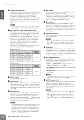
... to Pin 2 and 3 of 12 dB/ octave. all the way down. Turn the switch off if you do not need to mix a phasereversed signal. Owner's Manual 9 English NOTE · If you try to mix a phase-reversed signal, the signals will interfere with a low input level to the channel. Turn it on...
... to Pin 2 and 3 of 12 dB/ octave. all the way down. Turn the switch off if you do not need to mix a phasereversed signal. Owner's Manual 9 English NOTE · If you try to mix a phase-reversed signal, the signals will interfere with a low input level to the channel. Turn it on...
Owner's Manual
Page 10
... channel signal level after the channel fader (post-fader). J MUTE Switches (1-4) These assign the channel's mute on/off to your Yamaha dealer listed at the end of this manual. NOTE · Avoid setting the compression too high, as the higher average output level that results may lead to the even channels...A fee will light red when the input signal reaches 3 dB before the channel fader via the MONITOR OUT jacks and the PHONES jack. 10 Owner's Manual Rotate the knob clockwise to pan the signal to the odd channels of the GROUP buses and the ST L bus, and counter-clockwise to pan...
... channel signal level after the channel fader (post-fader). J MUTE Switches (1-4) These assign the channel's mute on/off to your Yamaha dealer listed at the end of this manual. NOTE · Avoid setting the compression too high, as the higher average output level that results may lead to the even channels...A fee will light red when the input signal reaches 3 dB before the channel fader via the MONITOR OUT jacks and the PHONES jack. 10 Owner's Manual Rotate the knob clockwise to pan the signal to the odd channels of the GROUP buses and the ST L bus, and counter-clockwise to pan...
Owner's Manual
Page 11
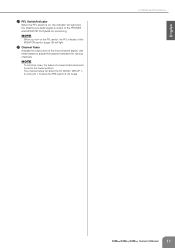
... minimize noise, the faders of the MONITOR section (page 18) will light and the channel pre-fader signal is off) buses. Controls and Functions Owner's Manual 11 Use these faders to the PHONES and MONITOR OUT jacks for monitoring. L Channel Fader Adjusts the output level of the input channel signal.
... minimize noise, the faders of the MONITOR section (page 18) will light and the channel pre-fader signal is off) buses. Controls and Functions Owner's Manual 11 Use these faders to the PHONES and MONITOR OUT jacks for monitoring. L Channel Fader Adjusts the output level of the input channel signal.

Owner's Manual
Page 12
...) MUTE MASTER Section (page 15) TALKBACK Section (page 15) AUX SEND Section (page 16) MONITOR Section (page 18) GROUP OUT Section (page 16) 12 Owner's Manual MONO Section (page 19) STEREO MASTER Section (page 17)
...) MUTE MASTER Section (page 15) TALKBACK Section (page 15) AUX SEND Section (page 16) MONITOR Section (page 18) GROUP OUT Section (page 16) 12 Owner's Manual MONO Section (page 19) STEREO MASTER Section (page 17)

Owner's Manual
Page 13
... the USB connector When connecting the computer to the USB connector, make sure to do so risks freezing the computer and corrupting or losing Owner's Manual 13 NOTE · When you connect to the L/MONO jack only, the mixer will recognize the signal as the REC OUT jacks. English STEREO AUX...
... the USB connector When connecting the computer to the USB connector, make sure to do so risks freezing the computer and corrupting or losing Owner's Manual 13 NOTE · When you connect to the L/MONO jack only, the mixer will recognize the signal as the REC OUT jacks. English STEREO AUX...
Owner's Manual
Page 14
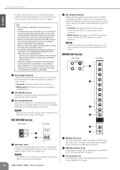
...; When you should wait for six seconds or more between these jacks. 6 1 MATRIX OUT Jack This is output to the MATRIX OUT jacks. 14 Owner's Manual Quit any power-saving mode of the signals sent from the 2TR IN jacks and the USB con-
...; When you should wait for six seconds or more between these jacks. 6 1 MATRIX OUT Jack This is output to the MATRIX OUT jacks. 14 Owner's Manual Quit any power-saving mode of the signals sent from the 2TR IN jacks and the USB con-
Owner's Manual
Page 15
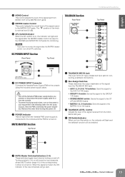
... 1 TALKBACK MIC IN Jack This is output to the console using the included power supply cable. • Turn off all PFL switches. Owner's Manual 15 Turning a switch (1-4) on will mute the input channels whose MUTE switch (page 10) of the input channels will light and the signal after ...the MATRIX master control, turn on . DC POWER INPUT Section Rear Panel NPUT Top Panel 1 2 1 DC POWER INPUT Connector Connects the Yamaha Power Supply PW8 to the PHONES and MONITOR OUT jacks for connecting a talkback microphone. 2 Bus Assign Switches These determine the output destination of...
... 1 TALKBACK MIC IN Jack This is output to the console using the included power supply cable. • Turn off all PFL switches. Owner's Manual 15 Turning a switch (1-4) on will mute the input channels whose MUTE switch (page 10) of the input channels will light and the signal after ...the MATRIX master control, turn on . DC POWER INPUT Section Rear Panel NPUT Top Panel 1 2 1 DC POWER INPUT Connector Connects the Yamaha Power Supply PW8 to the PHONES and MONITOR OUT jacks for connecting a talkback microphone. 2 Bus Assign Switches These determine the output destination of...

Owner's Manual
Page 16
... both the send and return signal (tip = send/out; To the input jack of the external processor To the INSERT jack Tip: OUT 16 Owner's Manual Sleeve (Ground) Ring: IN Tip: OUT Tip: IN To the output jack of the external processor
... both the send and return signal (tip = send/out; To the input jack of the external processor To the INSERT jack Tip: OUT 16 Owner's Manual Sleeve (Ground) Ring: IN Tip: OUT Tip: IN To the output jack of the external processor

Owner's Manual
Page 17
This is on , that GROUP OUT will be enabled and the indicator will light and the signal after the GROUP OUT fader. Owner's Manual 17 English 2 GROUP OUT Jacks These are TRS phone type impedance-balanced (page 19) output jacks that carries both the send and return signal (tip = ...
This is on , that GROUP OUT will be enabled and the indicator will light and the signal after the GROUP OUT fader. Owner's Manual 17 English 2 GROUP OUT Jacks These are TRS phone type impedance-balanced (page 19) output jacks that carries both the send and return signal (tip = ...
Owner's Manual
Page 18
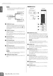
...-balanced (page 19) TRS phonetype output jacks that output the mixed stereo signal. NOTE · If you can connect to the PHONES jack. 18 Owner's Manual MONITOR Section Rear Panel Top Panel 1 Front Panel 2 3 4 5 6 1 MONITOR OUT Jacks These are XLR-3-32 type balanced output jacks that you want to monitor the...
...-balanced (page 19) TRS phonetype output jacks that output the mixed stereo signal. NOTE · If you can connect to the PHONES jack. 18 Owner's Manual MONITOR Section Rear Panel Top Panel 1 Front Panel 2 3 4 5 6 1 MONITOR OUT Jacks These are XLR-3-32 type balanced output jacks that you want to monitor the...
Owner's Manual
Page 19
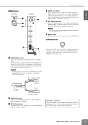
... The PEAK LED will light red when the MONO OUT signal reaches 3 dB before the MONO fader. sleeve = ground). The IM8-40 mixer has three of impedance balanced output jacks have two. LAMP Connector 6 5 1 MONO INSERT Jack This is a TRS ... external devices via an INSERT jack requires a special insert cable such as illustrated below (insert cable sold gooseneck lamp (e.g., Yamaha LA5000). To the INSERT jack Tip: OUT Sleeve (Ground) Ring: IN Tip: OUT Tip: IN To the output jack... is output to the MONITOR OUT and PHONES jacks for monitoring. Owner's Manual 19 ring = return/in;
... The PEAK LED will light red when the MONO OUT signal reaches 3 dB before the MONO fader. sleeve = ground). The IM8-40 mixer has three of impedance balanced output jacks have two. LAMP Connector 6 5 1 MONO INSERT Jack This is a TRS ... external devices via an INSERT jack requires a special insert cable such as illustrated below (insert cable sold gooseneck lamp (e.g., Yamaha LA5000). To the INSERT jack Tip: OUT Sleeve (Ground) Ring: IN Tip: OUT Tip: IN To the output jack... is output to the MONITOR OUT and PHONES jacks for monitoring. Owner's Manual 19 ring = return/in;
Owner's Manual
Page 20
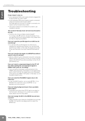
...PW8 power supply properly connected using multiple mics, phase reversal may be sent to select the MONO bus. 20 Owner's Manual The sound of the GROUP bus without sending it to the ST L/R (and MONO) bus. How can I send... portable audio player via the included power cable. • If the above checks do not identify the problem, call Yamaha for monitoring? • You can I play background music from a portable audio player? • A standard mini-...(or MATRIX 3-4) to the MONO bus and also record it is off the IM8's COMP control. How can I assign the MC to the intercom.
...PW8 power supply properly connected using multiple mics, phase reversal may be sent to select the MONO bus. 20 Owner's Manual The sound of the GROUP bus without sending it to the ST L/R (and MONO) bus. How can I send... portable audio player via the included power cable. • If the above checks do not identify the problem, call Yamaha for monitoring? • You can I play background music from a portable audio player? • A standard mini-...(or MATRIX 3-4) to the MONO bus and also record it is off the IM8's COMP control. How can I assign the MC to the intercom.

Owner's Manual
Page 21
..., check the web site below . If you do not register the software, you will be held responsible for registration. Note that Yamaha does not offer technical support for Windows and Macintosh. About the DAW software in the accessory disk The accessory disk contains DAW software ... part by any means is governed by Steinberg Media Technologies GmbH. For information about the minimum system requirements and latest information of this manual and the software. About software support Support for audio/visual purpose. ister the software and activate your player. Click the "Register Now...
..., check the web site below . If you do not register the software, you will be held responsible for registration. Note that Yamaha does not offer technical support for Windows and Macintosh. About the DAW software in the accessory disk The accessory disk contains DAW software ... part by any means is governed by Steinberg Media Technologies GmbH. For information about the minimum system requirements and latest information of this manual and the software. About software support Support for audio/visual purpose. ister the software and activate your player. Click the "Register Now...
Owner's Manual
Page 22
... This Agreement shall be binding unless in materials and workmanship under relevant copyrights. · You may not use of Yamaha. 22 Owner's Manual THIS AGREEMENT PROVIDES YOUR USE-CONDITIONS ABOUT THE "DAW" SOFTWARE OF STEINBERG MEDIA TECHNOLOGIES GMBH("STEINBERG") WHICH IS BUNDLED... paid for all applicable treaty provisions. THIS AGREEMENT IS BETWEEN YOU (AS AN INDIVIDUAL OR LEGAL ENTITY) AND YAMAHA CORPORATION ("YAMAHA"). English About the accessory disk ATTENTION SOFTWARE LICENSE AGREEMENT PLEASE READ THIS SOFTWARE LICENSE AGREEMENT ("AGREEMENT") CAREFULLY BEFORE USING...
... This Agreement shall be binding unless in materials and workmanship under relevant copyrights. · You may not use of Yamaha. 22 Owner's Manual THIS AGREEMENT PROVIDES YOUR USE-CONDITIONS ABOUT THE "DAW" SOFTWARE OF STEINBERG MEDIA TECHNOLOGIES GMBH("STEINBERG") WHICH IS BUNDLED... paid for all applicable treaty provisions. THIS AGREEMENT IS BETWEEN YOU (AS AN INDIVIDUAL OR LEGAL ENTITY) AND YAMAHA CORPORATION ("YAMAHA"). English About the accessory disk ATTENTION SOFTWARE LICENSE AGREEMENT PLEASE READ THIS SOFTWARE LICENSE AGREEMENT ("AGREEMENT") CAREFULLY BEFORE USING...

