
Owner's Manual
Page 2
...INFORMATION STATEMENT (DECLARATION OF CONFORMITY PROCEDURE) Responsible Party : Yamaha Corporation of America Address : 6600 Orangethorpe Ave., Buena Park, Calif. 90620 Telephone : 714-522-9011 Type of Equipment : MIXING CONSOLE Model Name : IM8-40/IM8-32/IM8-24 This device complies with these corrective measures do not... interference with this product MUST be the source of interference, which can not locate the appropriate retailer, please contact Yamaha Corporation of America, Electronic Service Division, 6600 Orangethorpe Ave, Buena Park, CA90620 The above statements apply ONLY to the...
...INFORMATION STATEMENT (DECLARATION OF CONFORMITY PROCEDURE) Responsible Party : Yamaha Corporation of America Address : 6600 Orangethorpe Ave., Buena Park, Calif. 90620 Telephone : 714-522-9011 Type of Equipment : MIXING CONSOLE Model Name : IM8-40/IM8-32/IM8-24 This device complies with these corrective measures do not... interference with this product MUST be the source of interference, which can not locate the appropriate retailer, please contact Yamaha Corporation of America, Electronic Service Division, 6600 Orangethorpe Ave, Buena Park, CA90620 The above statements apply ONLY to the...
Owner's Manual
Page 3
IMPORTANT SAFETY INSTRUCTIONS 1 Read these instructions. 2 Keep these instructions. 3 Heed all warnings. 4 Follow all servicing to qualified service personnel. A grounding type plug has two blades and a third grounding prong. The wide blade or the third prong are provided for replacement of the obsolete outlet. 10 Protect the power cord from the apparatus. 11 Only use this apparatus near any way, such as radiators, heat registers, stoves, or other . CAUTION RISK OF ELECTRIC SHOCK DO NOT OPEN CAUTION: TO REDUCE THE RISK OF ELECTRIC SHOCK, DO NOT REMOVE COVER (OR BACK). ...
IMPORTANT SAFETY INSTRUCTIONS 1 Read these instructions. 2 Keep these instructions. 3 Heed all warnings. 4 Follow all servicing to qualified service personnel. A grounding type plug has two blades and a third grounding prong. The wide blade or the third prong are provided for replacement of the obsolete outlet. 10 Protect the power cord from the apparatus. 11 Only use this apparatus near any way, such as radiators, heat registers, stoves, or other . CAUTION RISK OF ELECTRIC SHOCK DO NOT OPEN CAUTION: TO REDUCE THE RISK OF ELECTRIC SHOCK, DO NOT REMOVE COVER (OR BACK). ...
Owner's Manual
Page 4
... immediately and have the device inspected by the cord can cause permanent hearing loss. Then have the device inspected by qualified Yamaha service personnel. CAUTION Always follow the basic precautions listed below to minimum. Location • When transporting or moving the device, remove all... electric plug from the AC outlet. If this device or power supply should be malfunctioning, discontinue use it inspected by qualified Yamaha service personnel. • Do not apply oil, grease, or contact cleaner to avoid speaker damage. Do not open • Do ...
... immediately and have the device inspected by the cord can cause permanent hearing loss. Then have the device inspected by qualified Yamaha service personnel. CAUTION Always follow the basic precautions listed below to minimum. Location • When transporting or moving the device, remove all... electric plug from the AC outlet. If this device or power supply should be malfunctioning, discontinue use it inspected by qualified Yamaha service personnel. • Do not apply oil, grease, or contact cleaner to avoid speaker damage. Do not open • Do ...
Owner's Manual
Page 5
...in EN55103-1 and EN55103-2. Such copyrighted materials include, without prior notice. European models Purchaser/User Information specified in which Yamaha owns copyrights or with respect to which the purchaser fully agrees to upon breaking the seal of the software packaging. (Please ... manual and the software. • This disk containing the software is expressly forbidden without the written consent of the manufacturer. • Yamaha makes no representations or warranties with an audio/visual system (CD player, DVD player, etc.). Any unauthorized use . • Windows is...
...in EN55103-1 and EN55103-2. Such copyrighted materials include, without prior notice. European models Purchaser/User Information specified in which Yamaha owns copyrights or with respect to which the purchaser fully agrees to upon breaking the seal of the software packaging. (Please ... manual and the software. • This disk containing the software is expressly forbidden without the written consent of the manufacturer. • Yamaha makes no representations or warranties with an audio/visual system (CD player, DVD player, etc.). Any unauthorized use . • Windows is...
Owner's Manual
Page 6
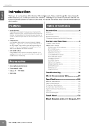
... The console provides 40 monaural input channels (the IM8-32 has 32 channels, and the IM8-24 has 24 channels) that you will be able to take full advantage of your mixer's superlative features and enjoy trouble-free operation for your purchase of the Yamaha IM8 mixing console. Using... Power supply cable • Cubase AI 4 DVD-ROM • USB cable Introduction 6 Features 6 Accessories 6 System Requirements 7 Differences between the IM8-40/32/24 mixers 7 Controls and Functions 8 Channel Control Section 8 Master Control Section 12 STEREO AUX RETURN Section 13 2TR IN/USB Section 13 REC...
... The console provides 40 monaural input channels (the IM8-32 has 32 channels, and the IM8-24 has 24 channels) that you will be able to take full advantage of your mixer's superlative features and enjoy trouble-free operation for your purchase of the Yamaha IM8 mixing console. Using... Power supply cable • Cubase AI 4 DVD-ROM • USB cable Introduction 6 Features 6 Accessories 6 System Requirements 7 Differences between the IM8-40/32/24 mixers 7 Controls and Functions 8 Channel Control Section 8 Master Control Section 12 STEREO AUX RETURN Section 13 2TR IN/USB Section 13 REC...

Owner's Manual
Page 7
...; Number of monaural input channels The IM8-40 provides 40 monaural input channels, the IM832 provides 32, and the IM8-24 provides 24. Owner's Manual 7 Differences between the IM8-40/32/24 mixers The IM8 mixer is available in three models (IM8-40, IM8-32, IM8-24) which differ as follows. •...; Number of LAMP connectors The IM8-40 provides three LAMP connectors to which you can connect separately sold gooseneck lamps (e.g., Yamaha LA5000), while the IM8-32 and IM8-24 ...
...; Number of monaural input channels The IM8-40 provides 40 monaural input channels, the IM832 provides 32, and the IM8-24 provides 24. Owner's Manual 7 Differences between the IM8-40/32/24 mixers The IM8 mixer is available in three models (IM8-40, IM8-32, IM8-24) which differ as follows. •...; Number of LAMP connectors The IM8-40 provides three LAMP connectors to which you can connect separately sold gooseneck lamps (e.g., Yamaha LA5000), while the IM8-32 and IM8-24 ...
Owner's Manual
Page 8
... as illustrated below (insert cable sold separately). NOTE · Only one type of the external processor To the INSERT jack Tip: OUT 1 4 2 3 Turn off the Yamaha PW8 power supply before you connect or disconnect any cables to or from the DIRECT OUT jack can connect either balanced or unbalanced phone plugs.... sleeve = ground). NOTE · If necessary, the signal that carry both the send and return signal (tip = send/out; A fee will be used to your Yamaha dealer listed at a time on a single channel. 8 Owner's Manual Cold; R;
... as illustrated below (insert cable sold separately). NOTE · Only one type of the external processor To the INSERT jack Tip: OUT 1 4 2 3 Turn off the Yamaha PW8 power supply before you connect or disconnect any cables to or from the DIRECT OUT jack can connect either balanced or unbalanced phone plugs.... sleeve = ground). NOTE · If necessary, the signal that carry both the send and return signal (tip = send/out; A fee will be used to your Yamaha dealer listed at a time on a single channel. 8 Owner's Manual Cold; R;

Owner's Manual
Page 9
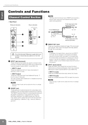
• Top Panel Monaural channels Stereo channels 5 6 7 8 9 0 A B C D E F G H I J K L Controls and Functions 5 +48V Switch/Indicator This switch toggles phantom power on or off. If you omit this precaution, you may be sure to turn the mixer's output controls - Turn it on ( ) if you try to mix a phase-reversed signal, the signals will be sure that lets you need phantom power. • When turning phantom power on if you change the range of the monaural channel. NOTE · If you 've connected a line-level device. 7 GAIN Control This adjusts the sensitivity of the...
• Top Panel Monaural channels Stereo channels 5 6 7 8 9 0 A B C D E F G H I J K L Controls and Functions 5 +48V Switch/Indicator This switch toggles phantom power on or off. If you omit this precaution, you may be sure to turn the mixer's output controls - Turn it on ( ) if you try to mix a phase-reversed signal, the signals will be sure that lets you need phantom power. • When turning phantom power on if you change the range of the monaural channel. NOTE · If you 've connected a line-level device. 7 GAIN Control This adjusts the sensitivity of the...
Owner's Manual
Page 10
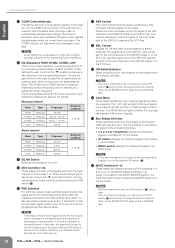
... ±15 dB B EQ ON Switch Switches the equalizer on or off , you can turn on the channel ON switch (G). For details, contact to your Yamaha dealer listed at the end of the bands. G ON Switch/Indicator When this switch is ON, the pre-fader signal is muted, you can turn...
... ±15 dB B EQ ON Switch Switches the equalizer on or off , you can turn on the channel ON switch (G). For details, contact to your Yamaha dealer listed at the end of the bands. G ON Switch/Indicator When this switch is ON, the pre-fader signal is muted, you can turn...
Owner's Manual
Page 11
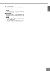
Use these faders to the PHONES and MONITOR OUT jacks for monitoring. Controls and Functions Owner's Manual 11 NOTE · To minimize noise, the faders of unused channels should be set to the lowest position. · The channel faders will affect the ST, MONO, GROUP 1- 8, and AUX 1-8 (when the PRE switch is output to adjust the balance between the various channels. L Channel Fader Adjusts the output level of the MONITOR section (page 18) will light. English K PFL Switch/Indicator When the PFL switch is on the PFL switch, the PFL indicator of the input channel signal. NOTE &#...
Use these faders to the PHONES and MONITOR OUT jacks for monitoring. Controls and Functions Owner's Manual 11 NOTE · To minimize noise, the faders of unused channels should be set to the lowest position. · The channel faders will affect the ST, MONO, GROUP 1- 8, and AUX 1-8 (when the PRE switch is output to adjust the balance between the various channels. L Channel Fader Adjusts the output level of the MONITOR section (page 18) will light. English K PFL Switch/Indicator When the PFL switch is on the PFL switch, the PFL indicator of the input channel signal. NOTE &#...

Owner's Manual
Page 12
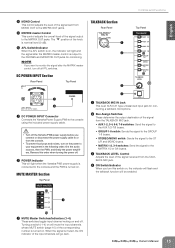
English Controls and Functions Master Control Section Rear Panel MONITOR Section (page 18) REC OUT/USB Section (page 14) TALKBACK Section (page 15) STEREO MASTER Section (page 17) MATRIX OUT Section (page 14) STEREO AUX RETURN Section (page 13) GROUP OUT Section (page 16) DC POWER INPUT 2TR IN/USB Section (page 13) MONO Section (page 19) Top Panel 2TR IN/USB Section (page 13) STEREO MASTER Section (page 17) AUX SEND Section (page 16) DC POWER INPUT Section (page 15) REC OUT/USB Section (page 14) MATRIX OUT Section (page 14) DC POWER INPUT Section (page 15) MUTE MASTER Section (...
English Controls and Functions Master Control Section Rear Panel MONITOR Section (page 18) REC OUT/USB Section (page 14) TALKBACK Section (page 15) STEREO MASTER Section (page 17) MATRIX OUT Section (page 14) STEREO AUX RETURN Section (page 13) GROUP OUT Section (page 16) DC POWER INPUT 2TR IN/USB Section (page 13) MONO Section (page 19) Top Panel 2TR IN/USB Section (page 13) STEREO MASTER Section (page 17) AUX SEND Section (page 16) DC POWER INPUT Section (page 15) REC OUT/USB Section (page 14) MATRIX OUT Section (page 14) DC POWER INPUT Section (page 15) MUTE MASTER Section (...

Owner's Manual
Page 13
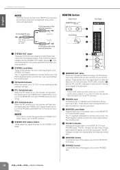
English STEREO AUX RETURN Section Rear Panel Top Panel 1 2 3 Controls and Functions 5 PFL Switch/Indicator When the PFL switch is on the PFL switch, the PFL indicator in the STEREO AUX RETURN section is nominal level (0 dB). Signals input from these jacks when you want to connect a CD player, and output the signal to do so risks freezing the computer and corrupting or losing Owner's Manual 13 This connector outputs the same signal as monaural and will send the identical signal to the MONITOR OUT and PHONES jacks for inputting a stereo audio source. Precautions when using ...
English STEREO AUX RETURN Section Rear Panel Top Panel 1 2 3 Controls and Functions 5 PFL Switch/Indicator When the PFL switch is on the PFL switch, the PFL indicator in the STEREO AUX RETURN section is nominal level (0 dB). Signals input from these jacks when you want to connect a CD player, and output the signal to do so risks freezing the computer and corrupting or losing Owner's Manual 13 This connector outputs the same signal as monaural and will send the identical signal to the MONITOR OUT and PHONES jacks for inputting a stereo audio source. Precautions when using ...
Owner's Manual
Page 14
Reverse this order when turning the power off or plugging/unplugging the USB cable to/from the 2TR IN jacks and the USB connector. 5 PFL Switch/Indicator When the PFL switch is output to the MATRIX OUT jacks. 14 Owner's Manual NOTE · If both the ST switch and the MONO switch are on /off . • Before connecting the computer to the USB connector, exit from any open application software on the PFL switch, the PFL indicator of the MONITOR section (page 18) will be output from ST OUT L/ R to the MON- nector is not being transmitted from the 2TR IN jacks and the USB con...
Reverse this order when turning the power off or plugging/unplugging the USB cable to/from the 2TR IN jacks and the USB connector. 5 PFL Switch/Indicator When the PFL switch is output to the MATRIX OUT jacks. 14 Owner's Manual NOTE · If both the ST switch and the MONO switch are on /off . • Before connecting the computer to the USB connector, exit from any open application software on the PFL switch, the PFL indicator of the MONITOR section (page 18) will be output from ST OUT L/ R to the MON- nector is not being transmitted from the 2TR IN jacks and the USB con...
Owner's Manual
Page 15
... go dark. DC POWER INPUT Section Rear Panel NPUT Top Panel 1 2 1 DC POWER INPUT Connector Connects the Yamaha Power Supply PW8 to the console using the included power supply cable. • Turn off the Yamaha PW8 power supply before you connect or disconnect the power supply cable to or from the console... from the TALKBACK MIC jack. 4 ON Switch/Indicator When you turn this order when turning the power off. 2 POWER Indicator This will light when the Yamaha PW8 power supply is turned on. When the signal is turned on and off. NOTE · If you want to the console and the PW8...
... go dark. DC POWER INPUT Section Rear Panel NPUT Top Panel 1 2 1 DC POWER INPUT Connector Connects the Yamaha Power Supply PW8 to the console using the included power supply cable. • Turn off the Yamaha PW8 power supply before you connect or disconnect the power supply cable to or from the console... from the TALKBACK MIC jack. 4 ON Switch/Indicator When you turn this order when turning the power off. 2 POWER Indicator This will light when the Yamaha PW8 power supply is turned on. When the signal is turned on and off. NOTE · If you want to the console and the PW8...

Owner's Manual
Page 16
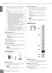
The "-20" LED will light if the output signal level reaches -20 dB, and the "0" LED will light and the signal after the AUX SEND fader is output to the AUX SEND jack. 5 AFL Switch/Indicator When the AFL switch is on, the indicator will light at nominal level. To the input jack of the external processor To the INSERT jack Tip: OUT 16 Owner's Manual Sleeve (Ground) Ring: IN Tip: OUT Tip: IN To the output jack of the external processor 2 AUX SEND Jacks These are balanced XLR-3-32 type output jacks (1: Ground; 2: Hot; 3: Cold). You can connect a graphic equalizer or other ...
The "-20" LED will light if the output signal level reaches -20 dB, and the "0" LED will light and the signal after the AUX SEND fader is output to the AUX SEND jack. 5 AFL Switch/Indicator When the AFL switch is on, the indicator will light at nominal level. To the input jack of the external processor To the INSERT jack Tip: OUT 16 Owner's Manual Sleeve (Ground) Ring: IN Tip: OUT Tip: IN To the output jack of the external processor 2 AUX SEND Jacks These are balanced XLR-3-32 type output jacks (1: Ground; 2: Hot; 3: Cold). You can connect a graphic equalizer or other ...

Owner's Manual
Page 17
You can connect these jacks to the ST L/R bus. This is an input/output jack located before clipping. 6 Bus Assign Switches These switches assign the GROUP OUT signal to the MONITOR OUT and PHONES jacks for monitoring. Rotate the knob clockwise to pan the signal right, and counter-clockwise to pan left. 4 ON Switch/Indicator When this switch is on, that GROUP OUT will be enabled and the indicator will light and the signal after the GROUP OUT fader. NOTE · Turn the ON switch on , the indicator will light. 5 GROUP OUT Meter Three LEDs indicate the signal level after the GROUP...
You can connect these jacks to the ST L/R bus. This is an input/output jack located before clipping. 6 Bus Assign Switches These switches assign the GROUP OUT signal to the MONITOR OUT and PHONES jacks for monitoring. Rotate the knob clockwise to pan the signal right, and counter-clockwise to pan left. 4 ON Switch/Indicator When this switch is on, that GROUP OUT will be enabled and the indicator will light and the signal after the GROUP OUT fader. NOTE · Turn the ON switch on , the indicator will light. 5 GROUP OUT Meter Three LEDs indicate the signal level after the GROUP...
Owner's Manual
Page 18
To the input jack of the external processor To the INSERT jack Tip: OUT Sleeve (Ground) Ring: IN Tip: OUT Tip: IN To the output jack of the signal output to the PHONES jack. 18 Owner's Manual These jacks output the signal before the faders (control) are being sent; the AFL indicator will light if the signals after the faders are on, the PFL switch will be enabled and the indicator will light. 5 PFL Switch/Indicator When the PFL switch is on, the indicator will light and the signal before or after the faders for the various buses. The PFL/AFL indicator (4) and the PFL and ...
To the input jack of the external processor To the INSERT jack Tip: OUT Sleeve (Ground) Ring: IN Tip: OUT Tip: IN To the output jack of the signal output to the PHONES jack. 18 Owner's Manual These jacks output the signal before the faders (control) are being sent; the AFL indicator will light if the signals after the faders are on, the PFL switch will be enabled and the indicator will light. 5 PFL Switch/Indicator When the PFL switch is on, the indicator will light and the signal before or after the faders for the various buses. The PFL/AFL indicator (4) and the PFL and ...
Owner's Manual
Page 19
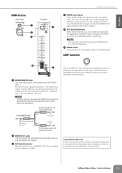
... the MONO fader. NOTE · If you want to monitor the signal after the MONO fader. sleeve = ground). The IM8-40 mixer has three of these connectors, and the IM8-32/24 mixers have the same output impedance, these output jacks are less affected by induced noise. ring = return/in; ... level. NOTE · Patching external devices via an INSERT jack requires a special insert cable such as illustrated below (insert cable sold gooseneck lamp (e.g., Yamaha LA5000). To the INSERT jack Tip: OUT Sleeve (Ground) Ring: IN Tip: OUT Tip: IN To the output jack of the external processor 2...
... the MONO fader. NOTE · If you want to monitor the signal after the MONO fader. sleeve = ground). The IM8-40 mixer has three of these connectors, and the IM8-32/24 mixers have the same output impedance, these output jacks are less affected by induced noise. ring = return/in; ... level. NOTE · Patching external devices via an INSERT jack requires a special insert cable such as illustrated below (insert cable sold gooseneck lamp (e.g., Yamaha LA5000). To the INSERT jack Tip: OUT Sleeve (Ground) Ring: IN Tip: OUT Tip: IN To the output jack of the external processor 2...
Owner's Manual
Page 20
... is provided on unless it is off. How can I send it to the ST L/R bus? • With the GROUP section ON switch turned off the IM8's COMP control. In this case, the signal will be causing cancellation. How can I send the TALKBACK signal only to the intercom? • In the TALKBACK.... • Could you to connect your portable audio player via the included power cable. • If the above checks do not identify the problem, call Yamaha for monitoring? • You can I send the pre-EQ signal to an AUX bus for service.
... is provided on unless it is off. How can I send it to the ST L/R bus? • With the GROUP section ON switch turned off the IM8's COMP control. In this case, the signal will be causing cancellation. How can I send the TALKBACK signal only to the intercom? • In the TALKBACK.... • Could you to connect your portable audio player via the included power cable. • If the above checks do not identify the problem, call Yamaha for monitoring? • You can I send the pre-EQ signal to an AUX bus for service.

Owner's Manual
Page 21
...cannot be unable to use of the software in the accessory disk The accessory disk contains DAW software both for audio/visual purpose. Note that Yamaha does not offer technical support for registration. Click the "Register Now" button shown when the software is provided by starting it after a ...limited period of the software and this manual and the software. Yamaha makes no representations or warranties with regard to play the disk on the software in the accessory disk. This disk is connected to upon ...
...cannot be unable to use of the software in the accessory disk The accessory disk contains DAW software both for audio/visual purpose. Note that Yamaha does not offer technical support for registration. Click the "Register Now" button shown when the software is provided by starting it after a ...limited period of the software and this manual and the software. Yamaha makes no representations or warranties with regard to play the disk on the software in the accessory disk. This disk is connected to upon ...
