
Owner's Manual
Page 2
... or its subsidiaries. (class B) COMPLIANCE INFORMATION STATEMENT (DECLARATION OF CONFORMITY PROCEDURE) Responsible Party : Yamaha Corporation of America Address : 6600 Orangethorpe Ave., Buena Park, Calif. 90620 Telephone : 714-522-9011 Type of Equipment : MIXING CONSOLE Model Name : IM8-40/IM8-32/IM8-24 This device complies with FCC regulations does not guarantee * This applies only to...
... or its subsidiaries. (class B) COMPLIANCE INFORMATION STATEMENT (DECLARATION OF CONFORMITY PROCEDURE) Responsible Party : Yamaha Corporation of America Address : 6600 Orangethorpe Ave., Buena Park, Calif. 90620 Telephone : 714-522-9011 Type of Equipment : MIXING CONSOLE Model Name : IM8-40/IM8-32/IM8-24 This device complies with FCC regulations does not guarantee * This applies only to...
Owner's Manual
Page 6
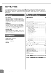
...8226; Power supply cable • Cubase AI 4 DVD-ROM • USB cable Introduction 6 Features 6 Accessories 6 System Requirements 7 Differences between the IM8-40/32/24 mixers 7 Controls and Functions 8 Channel Control Section 8 Master Control Section 12 STEREO AUX RETURN Section 13 2TR IN/USB Section 13 REC ...of Contents • Input channels The console provides 40 monaural input channels (the IM8-32 has 32 channels, and the IM8-24 has 24 channels) that you will be able to take full advantage of your purchase of the Yamaha IM8 mixing console. Please read the manual, keep it...
...8226; Power supply cable • Cubase AI 4 DVD-ROM • USB cable Introduction 6 Features 6 Accessories 6 System Requirements 7 Differences between the IM8-40/32/24 mixers 7 Controls and Functions 8 Channel Control Section 8 Master Control Section 12 STEREO AUX RETURN Section 13 2TR IN/USB Section 13 REC ...of Contents • Input channels The console provides 40 monaural input channels (the IM8-32 has 32 channels, and the IM8-24 has 24 channels) that you will be able to take full advantage of your purchase of the Yamaha IM8 mixing console. Please read the manual, keep it...

Owner's Manual
Page 7
Owner's Manual 7 Differences between the IM8-40/32/24 mixers The IM8 mixer is available in three models (IM8-40, IM8-32, IM8-24) which you can connect separately sold gooseneck lamps (e.g., Yamaha LA5000), while the IM8-32 and IM8-24 provide two such connectors. The remaining channels (stereo input channels, 2TR IN, etc.) are the same for all models. •...
Owner's Manual 7 Differences between the IM8-40/32/24 mixers The IM8 mixer is available in three models (IM8-40, IM8-32, IM8-24) which you can connect separately sold gooseneck lamps (e.g., Yamaha LA5000), while the IM8-32 and IM8-24 provide two such connectors. The remaining channels (stereo input channels, 2TR IN, etc.) are the same for all models. •...
Owner's Manual
Page 19
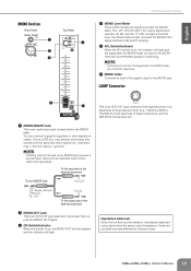
...6 5 1 MONO INSERT Jack This is a TRS (tip, ring, sleeve) phone jack that supplies power to a separately sold separately). The IM8-40 mixer has three of impedance balanced output jacks have two. Owner's Manual 19 Impedance balanced: Since the hot and cold terminals of these connectors, and...· Patching external devices via an INSERT jack requires a special insert cable such as illustrated below (insert cable sold gooseneck lamp (e.g., Yamaha LA5000). NOTE · If you want to monitor the signal after the MONO fader. This is an input/output jack located before ...
...6 5 1 MONO INSERT Jack This is a TRS (tip, ring, sleeve) phone jack that supplies power to a separately sold separately). The IM8-40 mixer has three of impedance balanced output jacks have two. Owner's Manual 19 Impedance balanced: Since the hot and cold terminals of these connectors, and...· Patching external devices via an INSERT jack requires a special insert cable such as illustrated below (insert cable sold gooseneck lamp (e.g., Yamaha LA5000). NOTE · If you want to monitor the signal after the MONO fader. This is an input/output jack located before ...

Owner's Manual
Page 24
... and controls are nominal when measured. (The nominal position is 10 dB lower than the maximum position.) Output impedance of signal generator: 150 ohms * IM8-40: 1-40, IM8-32: 1-32, IM8-24: 1-24 Italiano 166 Owner's Manual equivalent to Output STEREO OUT L/R, MOMO CH INPUT*, PAN: panned hard left or hard right. AUX SEND faders...
... and controls are nominal when measured. (The nominal position is 10 dB lower than the maximum position.) Output impedance of signal generator: 150 ohms * IM8-40: 1-40, IM8-32: 1-32, IM8-24: 1-24 Italiano 166 Owner's Manual equivalent to Output STEREO OUT L/R, MOMO CH INPUT*, PAN: panned hard left or hard right. AUX SEND faders...
Owner's Manual
Page 25
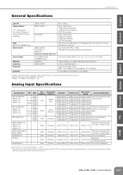
... maximum position.) Output impedance of signal generator: 150 ohms * IM8-40: 1-40, IM8-32: 1-32, IM8-24: 1-24 Analog Input Specifications Input Connectors INPUT A (MONO CHs) IM8-40: 1-40 IM8-32: 1-32 IM8-40: 1-24 INPUT B (MONO CHs) IM8-40: 1-40 IM8-32: 1-32 IM8-40: 1-24 INPUT A/B (ST CHs) INSERT IN (MONO CHs) IM8-40: 1-40 IM8-32: 1-32 IM8-40: 1-24 INSERT IN (AUX, GROUP, STEREO, MONO) AUX RETURN...
... maximum position.) Output impedance of signal generator: 150 ohms * IM8-40: 1-40, IM8-32: 1-32, IM8-24: 1-24 Analog Input Specifications Input Connectors INPUT A (MONO CHs) IM8-40: 1-40 IM8-32: 1-32 IM8-40: 1-24 INPUT B (MONO CHs) IM8-40: 1-40 IM8-32: 1-32 IM8-40: 1-24 INPUT A/B (ST CHs) INSERT IN (MONO CHs) IM8-40: 1-40 IM8-32: 1-32 IM8-40: 1-24 INSERT IN (AUX, GROUP, STEREO, MONO) AUX RETURN...

Owner's Manual
Page 26
...; Lines 600 Ω Lines 10 kΩ Lines 600 Ω Lines 10 kΩ Lines 10 kΩ Lines 10 kΩ Lines 10 kΩ Lines 10 kΩ Lines 40 Ω Phones Nominal Level +4 dBu (1.23 V) +4 dBu (1.23 V) +4 dBu (1.23 V) +4 dBu (1.23 V) +4 dBu (1.23 V) 0 dBu (0.775 V) 0 dBu (0.775 V) 0 dBu (0.775 V) -10 dBV (0.316 V) +4 dBu (1.23...
...; Lines 600 Ω Lines 10 kΩ Lines 600 Ω Lines 10 kΩ Lines 10 kΩ Lines 10 kΩ Lines 10 kΩ Lines 10 kΩ Lines 40 Ω Phones Nominal Level +4 dBu (1.23 V) +4 dBu (1.23 V) +4 dBu (1.23 V) +4 dBu (1.23 V) +4 dBu (1.23 V) 0 dBu (0.775 V) 0 dBu (0.775 V) 0 dBu (0.775 V) -10 dBV (0.316 V) +4 dBu (1.23...
Owner's Manual
Page 32
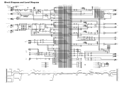
... Diagram CH INPUT [-60dBu to -16dBu] [-34dBu to +10dBu] 24ch : CH1 to 24 32ch : CH1 to 32 40ch : CH1 to 40 INPUT A INPUT B INSERT I/O [0dBu] DIRECT OUT [0dBu] ST CH INPUT 1 to 4 LINE L [-34dBu to +10dBu] LINE ...dBu +10 dBu CH INPUT A, B [+10dBu] 0 dBu -10 dBu -20 dBu CHINPUT A, B [-16dBu] -30 dBu -40 dBu CH INPUT A, B [-34dBu] -50 dBu -60 dBu CH INPUT A, B [-60dBu] 24ch:CH1 to 24, 32ch:CH1 to 32, 40ch...:CH1 to 40 PHANTOM +48V RE PAD HA N INV R PAD GAIN [-60dBu to -16dBu] [-34dBu to +10dBu] [0dBu] HPF ...
... Diagram CH INPUT [-60dBu to -16dBu] [-34dBu to +10dBu] 24ch : CH1 to 24 32ch : CH1 to 32 40ch : CH1 to 40 INPUT A INPUT B INSERT I/O [0dBu] DIRECT OUT [0dBu] ST CH INPUT 1 to 4 LINE L [-34dBu to +10dBu] LINE ...dBu +10 dBu CH INPUT A, B [+10dBu] 0 dBu -10 dBu -20 dBu CHINPUT A, B [-16dBu] -30 dBu -40 dBu CH INPUT A, B [-34dBu] -50 dBu -60 dBu CH INPUT A, B [-60dBu] 24ch:CH1 to 24, 32ch:CH1 to 32, 40ch...:CH1 to 40 PHANTOM +48V RE PAD HA N INV R PAD GAIN [-60dBu to -16dBu] [-34dBu to +10dBu] [0dBu] HPF ...
