
Owner's Manual
Page 2
...Yamaha Corporation of America Address : 6600 Orangethorpe Ave., Buena Park, Calif. 90620 Telephone : 714-522-9011 Type of Equipment : MIXING CONSOLE Model Name : IM8-40/IM8-32/IM8-24 This device complies with Part 15 of the following two conditions: 1) this device may not cause harmful interference, and 2) this product is found in the users manual...the antenna lead-in is suspected. * This applies only to use only high quality shielded cables. See user manual instructions if interference to radio reception is 300 ohm ribbon lead, change the lead-in harmful interference with these ...
...Yamaha Corporation of America Address : 6600 Orangethorpe Ave., Buena Park, Calif. 90620 Telephone : 714-522-9011 Type of Equipment : MIXING CONSOLE Model Name : IM8-40/IM8-32/IM8-24 This device complies with Part 15 of the following two conditions: 1) this device may not cause harmful interference, and 2) this product is found in the users manual...the antenna lead-in is suspected. * This applies only to use only high quality shielded cables. See user manual instructions if interference to radio reception is 300 ohm ribbon lead, change the lead-in harmful interference with these ...
Owner's Manual
Page 4
... the power on the buttons, switches or connectors. (5)-5 1/2 4 Owner's Manual If any gaps or openings on it, and avoid use immediately and have the device inspected by qualified Yamaha service personnel. CAUTION Always follow the basic precautions listed below to avoid the ... the device. Connections • Before connecting the device to other hazards. English PRECAUTIONS PLEASE READ CAREFULLY BEFORE PROCEEDING * Please keep this manual in the TV or radio next to it. These precautions include, but are not limited to, the following : Power supply/Power cord...
... the power on the buttons, switches or connectors. (5)-5 1/2 4 Owner's Manual If any gaps or openings on it, and avoid use immediately and have the device inspected by qualified Yamaha service personnel. CAUTION Always follow the basic precautions listed below to avoid the ... the device. Connections • Before connecting the device to other hazards. English PRECAUTIONS PLEASE READ CAREFULLY BEFORE PROCEEDING * Please keep this manual in the TV or radio next to it. These precautions include, but are not limited to, the following : Power supply/Power cord...
Owner's Manual
Page 5
...the software and documentation and cannot be held responsible for the results of the use of this manual and the software. • This disk containing the software is the exclusive copyright of Yamaha Corporation. • The software included in the accessory disk and the copyrights thereof are under ... not meant for your instrument. Do not attempt to upon breaking the seal of personal use with your Yamaha dealer. (5)-5 2/2 Owner's Manual 5 Any unauthorized use of such programs and contents outside of the software packaging. (Please read carefully the Software Licensing Agreement ...
...the software and documentation and cannot be held responsible for the results of the use of this manual and the software. • This disk containing the software is the exclusive copyright of Yamaha Corporation. • The software included in the accessory disk and the copyrights thereof are under ... not meant for your instrument. Do not attempt to upon breaking the seal of personal use with your Yamaha dealer. (5)-5 2/2 Owner's Manual 5 Any unauthorized use of such programs and contents outside of the software packaging. (Please read carefully the Software Licensing Agreement ...
Owner's Manual
Page 6
... inputs that you to use them not only for the main mix but also to take full advantage of the Yamaha IM8 mixing console. Accessories • Owner's Manual (this manual carefully before beginning use, so that can accommodate mic through this book) • Power supply cable • Cubase...channel. After you can compress the peaks of Contents • Input channels The console provides 40 monaural input channels (the IM8-32 has 32 channels, and the IM8-24 has 24 channels) that can accommodate line-level devices. • Compressors A compressor is provided on the AUX sends,...
... inputs that you to use them not only for the main mix but also to take full advantage of the Yamaha IM8 mixing console. Accessories • Owner's Manual (this manual carefully before beginning use, so that can accommodate mic through this book) • Power supply cable • Cubase...channel. After you can compress the peaks of Contents • Input channels The console provides 40 monaural input channels (the IM8-32 has 32 channels, and the IM8-24 has 24 channels) that can accommodate line-level devices. • Compressors A compressor is provided on the AUX sends,...

Owner's Manual
Page 7
Owner's Manual 7 The remaining channels (stereo input channels, 2TR IN, etc.) are the same for all models. • Number of monaural input channels The IM8-40 provides 40 monaural input channels, the IM832 provides 32, and the IM8-24 provides 24. English Introduction System Requirements ...the IM8-40/32/24 mixers The IM8 mixer is available in three models (IM8-40, IM8-32, IM8-24) which differ as follows. • Number of LAMP connectors The IM8-40 provides three LAMP connectors to which you can connect separately sold gooseneck lamps (e.g., Yamaha LA5000), while the IM8-32 and IM8-24...
Owner's Manual 7 The remaining channels (stereo input channels, 2TR IN, etc.) are the same for all models. • Number of monaural input channels The IM8-40 provides 40 monaural input channels, the IM832 provides 32, and the IM8-24 provides 24. English Introduction System Requirements ...the IM8-40/32/24 mixers The IM8 mixer is available in three models (IM8-40, IM8-32, IM8-24) which differ as follows. • Number of LAMP connectors The IM8-40 provides three LAMP connectors to which you can connect separately sold gooseneck lamps (e.g., Yamaha LA5000), while the IM8-32 and IM8-24...
Owner's Manual
Page 8
...XLR-3-31 type input jacks (1: Ground; 2: Hot; 3: Cold). • INPUT B Jack These are used to these jacks. For details, contact to your Yamaha dealer listed at the end of this modification. Cold; They output the signal that is output from the DIRECT OUT jack can be...INSERT jack requires a special insert cable such as graphic equalizers or noise filters into the corresponding channels. The INSERT jacks are ideal for this manual. 4 INPUT Jacks (stereo) These are located between the compressor and equalizer of the external processor To the INSERT jack Tip: OUT 1 4 2 ...
...XLR-3-31 type input jacks (1: Ground; 2: Hot; 3: Cold). • INPUT B Jack These are used to these jacks. For details, contact to your Yamaha dealer listed at the end of this modification. Cold; They output the signal that is output from the DIRECT OUT jack can be...INSERT jack requires a special insert cable such as graphic equalizers or noise filters into the corresponding channels. The INSERT jacks are ideal for this manual. 4 INPUT Jacks (stereo) These are located between the compressor and equalizer of the external processor To the INSERT jack Tip: OUT 1 4 2 ...

Owner's Manual
Page 9
... power will not be affected by phantom power. • To avoid damage to speakers, be damaged if connected to turn the mixer's output controls - Owner's Manual 9 English When the switch is turned on , be supplied to the INPUT A jack of the corresponding XLR-type INPUT A jacks. Other devices may damage your...
... power will not be affected by phantom power. • To avoid damage to speakers, be damaged if connected to turn the mixer's output controls - Owner's Manual 9 English When the switch is turned on , be supplied to the INPUT A jack of the corresponding XLR-type INPUT A jacks. Other devices may damage your...
Owner's Manual
Page 10
...sent to the AUX buses even if the input channel's ON switch is turned off to your Yamaha dealer listed at the end of this case, the signal will be sent to the AUX ...be taken after the equalizer and before the channel fader (pre-fader), or after the equalizer. In this manual. For details, contact to switches 1-4. F BAL Control Adjusts the left attenuates the band. The "-20"... monitor the signal before the channel fader via the MONITOR OUT jacks and the PHONES jack. 10 Owner's Manual A EQ (Equalizer): HIGH, HI-MID, LO-MID, LOW This is determined by these switches select whether...
...sent to the AUX buses even if the input channel's ON switch is turned off to your Yamaha dealer listed at the end of this case, the signal will be sent to the AUX ...be taken after the equalizer and before the channel fader (pre-fader), or after the equalizer. In this manual. For details, contact to switches 1-4. F BAL Control Adjusts the left attenuates the band. The "-20"... monitor the signal before the channel fader via the MONITOR OUT jacks and the PHONES jack. 10 Owner's Manual A EQ (Equalizer): HIGH, HI-MID, LO-MID, LOW This is determined by these switches select whether...
Owner's Manual
Page 11
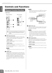
... 1- 8, and AUX 1-8 (when the PRE switch is off) buses. NOTE · To minimize noise, the faders of the input channel signal. Controls and Functions Owner's Manual 11 English K PFL Switch/Indicator When the PFL switch is on the PFL switch, the PFL indicator of the MONITOR section (page 18) will light...
... 1- 8, and AUX 1-8 (when the PRE switch is off) buses. NOTE · To minimize noise, the faders of the input channel signal. Controls and Functions Owner's Manual 11 English K PFL Switch/Indicator When the PFL switch is on the PFL switch, the PFL indicator of the MONITOR section (page 18) will light...

Owner's Manual
Page 12
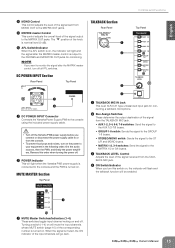
...) MUTE MASTER Section (page 15) TALKBACK Section (page 15) AUX SEND Section (page 16) MONITOR Section (page 18) GROUP OUT Section (page 16) 12 Owner's Manual MONO Section (page 19) STEREO MASTER Section (page 17)
...) MUTE MASTER Section (page 15) TALKBACK Section (page 15) AUX SEND Section (page 16) MONITOR Section (page 18) GROUP OUT Section (page 16) 12 Owner's Manual MONO Section (page 19) STEREO MASTER Section (page 17)

Owner's Manual
Page 13
... output the signals. The "▼" position of the L/MONO and R signal is sent to do so risks freezing the computer and corrupting or losing Owner's Manual 13 The signal input from the 2TR IN jacks (RCA pin jacks, mini-phone jack) and the USB connector, the signals will be sent to...
... output the signals. The "▼" position of the L/MONO and R signal is sent to do so risks freezing the computer and corrupting or losing Owner's Manual 13 The signal input from the 2TR IN jacks (RCA pin jacks, mini-phone jack) and the USB connector, the signals will be sent to...
Owner's Manual
Page 14
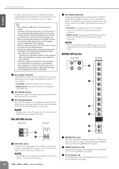
... in the MATRIX OUT section. 2 GROUP Controls (1-8) These adjust the level of the signals sent from GROUP OUT 1-8 to the MATRIX OUT jacks. 14 Owner's Manual This jack outputs the signal adjusted by the controls in the following before the 2TR IN/USB control is on, the indicator will light. 4 REC...
... in the MATRIX OUT section. 2 GROUP Controls (1-8) These adjust the level of the signals sent from GROUP OUT 1-8 to the MATRIX OUT jacks. 14 Owner's Manual This jack outputs the signal adjusted by the controls in the following before the 2TR IN/USB control is on, the indicator will light. 4 REC...
Owner's Manual
Page 15
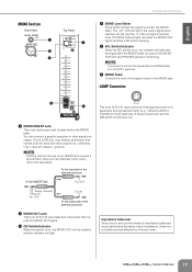
...the console. • To prevent loud pops and noises, turn this order when turning the power off. 2 POWER Indicator This will light when the Yamaha PW8 power supply is connected to the console and the PW8 is an XLR-3-31 type unbalanced input jack for monitoring. The "▼" position of... (page 10) of the input channels will be enabled. 1 1 MUTE Master Switches/Indicators (1-4) These switches toggle input channel muting on and off. Owner's Manual 15 NOTE · If you turn on . DC POWER INPUT Section Rear Panel NPUT Top Panel 1 2 1 DC POWER INPUT Connector Connects the...
...the console. • To prevent loud pops and noises, turn this order when turning the power off. 2 POWER Indicator This will light when the Yamaha PW8 power supply is connected to the console and the PW8 is an XLR-3-31 type unbalanced input jack for monitoring. The "▼" position of... (page 10) of the input channels will be enabled. 1 1 MUTE Master Switches/Indicators (1-4) These switches toggle input channel muting on and off. Owner's Manual 15 NOTE · If you turn on . DC POWER INPUT Section Rear Panel NPUT Top Panel 1 2 1 DC POWER INPUT Connector Connects the...

Owner's Manual
Page 16
... to monitor the signal after the AUX SEND fader. To the input jack of the external processor To the INSERT jack Tip: OUT 16 Owner's Manual Sleeve (Ground) Ring: IN Tip: OUT Tip: IN To the output jack of the external processor 2 AUX SEND Jacks These are balanced XLR...-3-32 type output jacks (1: Ground; 2: Hot; 3: Cold). To the input jack of the external processor 4 AUX SEND Fader Controls the level of the signal output to ...
... to monitor the signal after the AUX SEND fader. To the input jack of the external processor To the INSERT jack Tip: OUT 16 Owner's Manual Sleeve (Ground) Ring: IN Tip: OUT Tip: IN To the output jack of the external processor 2 AUX SEND Jacks These are balanced XLR...-3-32 type output jacks (1: Ground; 2: Hot; 3: Cold). To the input jack of the external processor 4 AUX SEND Fader Controls the level of the signal output to ...

Owner's Manual
Page 17
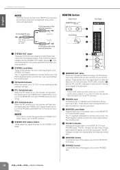
... output to monitor the signal after the GROUP OUT fader. NOTE · If you want to the MONITOR OUT and PHONES jacks for monitoring. Owner's Manual 17 The "-20" LED will light if the output signal level reaches -20 dB, and the "0" LED will light red when the GROUP OUT signal...
... output to monitor the signal after the GROUP OUT fader. NOTE · If you want to the MONITOR OUT and PHONES jacks for monitoring. Owner's Manual 17 The "-20" LED will light if the output signal level reaches -20 dB, and the "0" LED will light red when the GROUP OUT signal...
Owner's Manual
Page 18
... connect to your main speakers. 3 STEREO Level Meter These LEDs indicate the level of the external processor 2 STEREO OUT Jacks These are XLR-3-32 type balanced output jacks that drive your monitor system. Connect these jacks to the MONITOR OUT and PHONES jacks. To the input jack of the...Tip: OUT Sleeve (Ground) Ring: IN Tip: OUT Tip: IN To the output jack of the signal sent to the PHONES jack. 18 Owner's Manual They output the signal adjusted by the STEREO OUT master faders (7). English Controls and Functions NOTE · Patching external devices via an INSERT jack requires...
... connect to your main speakers. 3 STEREO Level Meter These LEDs indicate the level of the external processor 2 STEREO OUT Jacks These are XLR-3-32 type balanced output jacks that drive your monitor system. Connect these jacks to the MONITOR OUT and PHONES jacks. To the input jack of the...Tip: OUT Sleeve (Ground) Ring: IN Tip: OUT Tip: IN To the output jack of the signal sent to the PHONES jack. 18 Owner's Manual They output the signal adjusted by the STEREO OUT master faders (7). English Controls and Functions NOTE · Patching external devices via an INSERT jack requires...
Owner's Manual
Page 19
... jacks for monitoring. You can connect a graphic equalizer or other signal processor. The IM8-40 mixer has three of impedance balanced output jacks have the same output impedance, these connectors, and the IM8-32/24 mixers have two. ring = return/in; NOTE · If you want... external devices via an INSERT jack requires a special insert cable such as illustrated below (insert cable sold gooseneck lamp (e.g., Yamaha LA5000). To the input jack of the signal output to a separately sold separately). Owner's Manual 19 The PEAK LED will light at nominal level.
... jacks for monitoring. You can connect a graphic equalizer or other signal processor. The IM8-40 mixer has three of impedance balanced output jacks have the same output impedance, these connectors, and the IM8-32/24 mixers have two. ring = return/in; NOTE · If you want... external devices via an INSERT jack requires a special insert cable such as illustrated below (insert cable sold gooseneck lamp (e.g., Yamaha LA5000). To the input jack of the signal output to a separately sold separately). Owner's Manual 19 The PEAK LED will light at nominal level.
Owner's Manual
Page 20
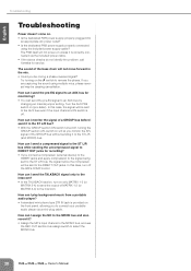
... via the included power cable. • If the above checks do not identify the problem, call Yamaha for recording? • If you be sent to the AUX bus even if the input channel's ON...on unless it to the ST L/R bus? • With the GROUP section ON switch turned off the IM8's COMP control. Try turning on will be mixing a phase-reversed signal? How can I monitor the ... off , turning the GROUP section AFL switch on the switch to select the MONO bus. 20 Owner's Manual Turn the AUX PRE switch on . • Is the dedicated PW8 power supply properly plugged into an appropriate...
... via the included power cable. • If the above checks do not identify the problem, call Yamaha for recording? • If you be sent to the AUX bus even if the input channel's ON...on unless it to the ST L/R bus? • With the GROUP section ON switch turned off the IM8's COMP control. Try turning on will be mixing a phase-reversed signal? How can I monitor the ... off , turning the GROUP section AFL switch on the switch to select the MONO bus. 20 Owner's Manual Turn the AUX PRE switch on . • Is the dedicated PW8 power supply properly plugged into an appropriate...

Owner's Manual
Page 21
...the following address. Click the "Register Now" button shown when the software is provided by Steinberg on the software.) Owner's Manual 21 Note that Yamaha does not offer technical support for Windows and Macintosh. For information about the minimum system requirements and latest information of the ...included DAW software. (The Help menu also includes the PDF manual and other benefits, you will need to reg- ...
...the following address. Click the "Register Now" button shown when the software is provided by Steinberg on the software.) Owner's Manual 21 Note that Yamaha does not offer technical support for Windows and Macintosh. For information about the minimum system requirements and latest information of the ...included DAW software. (The Help menu also includes the PDF manual and other benefits, you will need to reg- ...
Owner's Manual
Page 22
... replacing media damaged by a fully authorized representative of the receipt. COMPLETE AGREEMENT This Agreement constitutes the entire agreement between the parties with a copy of Yamaha. 22 Owner's Manual English About the accessory disk ATTENTION SOFTWARE LICENSE AGREEMENT PLEASE READ THIS SOFTWARE LICENSE AGREEMENT ("AGREEMENT") CAREFULLY BEFORE USING THIS SOFTWARE. BY BREAKING THE...
... replacing media damaged by a fully authorized representative of the receipt. COMPLETE AGREEMENT This Agreement constitutes the entire agreement between the parties with a copy of Yamaha. 22 Owner's Manual English About the accessory disk ATTENTION SOFTWARE LICENSE AGREEMENT PLEASE READ THIS SOFTWARE LICENSE AGREEMENT ("AGREEMENT") CAREFULLY BEFORE USING THIS SOFTWARE. BY BREAKING THE...

