
MCXSP10 Manual
Page 1
U HTR-5860 AV Receiver OWNER'S MANUAL
U HTR-5860 AV Receiver OWNER'S MANUAL
MCXSP10 Manual
Page 2
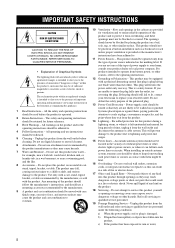
NO USER-SERVICEABLE PARTS INSIDE. The safety and operating instructions should never be retained for future reference. 3 Heed Warnings - Unplug this product near water - for long periods of the product and to rain or water, i The openings should be blocked by placing the product on an unstable cart, stand, tripod, bracket, or table. For products intended to operate from overheating, and these openings must not be located in a risk of power source indicated on the product. 18 Servicing - This plug will prevent damage to the product due to replace your product dealer ...
NO USER-SERVICEABLE PARTS INSIDE. The safety and operating instructions should never be retained for future reference. 3 Heed Warnings - Unplug this product near water - for long periods of the product and to rain or water, i The openings should be blocked by placing the product on an unstable cart, stand, tripod, bracket, or table. For products intended to operate from overheating, and these openings must not be located in a risk of power source indicated on the product. 18 Servicing - This plug will prevent damage to the product due to replace your product dealer ...
MCXSP10 Manual
Page 3
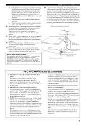
... GROUNDING CONDUCTORS (NEC SECTION 810-21) GROUND CLAMPS POWER SERVICE GROUNDING ELECTRODE SYSTEM (NEC ART 250. Modifications not expressly approved by Yamaha may cause interference harmful to those controls that the cable ground shall be sure the antenna or cable system is 300 ohm ribbon ...or the device that produce heat. The unit should be the source of interference, which can not locate the appropriate retailer, please contact Yamaha Electronics Corp., U.S.A. 6660 Orangethorpe Ave, Buena Park, CA 90620. The product should be used replacement parts specified by the manufacturer or...
... GROUNDING CONDUCTORS (NEC SECTION 810-21) GROUND CLAMPS POWER SERVICE GROUNDING ELECTRODE SYSTEM (NEC ART 250. Modifications not expressly approved by Yamaha may cause interference harmful to those controls that the cable ground shall be sure the antenna or cable system is 300 ohm ribbon ...or the device that produce heat. The unit should be the source of interference, which can not locate the appropriate retailer, please contact Yamaha Electronics Corp., U.S.A. 6660 Orangethorpe Ave, Buena Park, CA 90620. The product should be used replacement parts specified by the manufacturer or...
MCXSP10 Manual
Page 4
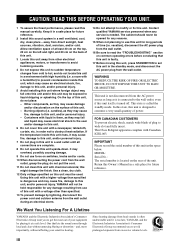
... use this unit for future reference. 2 Install this Owner's Manual in the space below. Burning objects (i.e. Containers with chemical solvents; YAMAHA will not be used. This unit is not disconnected from loud sounds is often undetectable until all connections are complete. 8 Do not ...of your sensitive hearing. It may cause fire, damage to wide slot and fully insert. We Want You Listening For A Lifetime YAMAHA and the Electronic Industries Association's Consumer Electronics Group want you to obstruct heat radiation. away from the wall outlet during an electrical...
... use this unit for future reference. 2 Install this Owner's Manual in the space below. Burning objects (i.e. Containers with chemical solvents; YAMAHA will not be used. This unit is not disconnected from loud sounds is often undetectable until all connections are complete. 8 Do not ...of your sensitive hearing. It may cause fire, damage to wide slot and fully insert. We Want You Listening For A Lifetime YAMAHA and the Electronic Industries Association's Consumer Electronics Group want you to obstruct heat radiation. away from the wall outlet during an electrical...
MCXSP10 Manual
Page 5
... 39 Selecting preset stations 41 Exchanging preset stations 42 XM SATELLITE RADIO TUNING 44 What is XM Satellite Radio 44 XM Satellite Radio connections 44 XM Satellite Radio functions 45 Activating XM Satellite Radio 46 Basic XM Satellite Radio operations 47 XM Satellite Radio search modes 48 Setting XM Satellite Radio preset channels 51 RECORDING 54 SOUND FIELD...
... 39 Selecting preset stations 41 Exchanging preset stations 42 XM SATELLITE RADIO TUNING 44 What is XM Satellite Radio 44 XM Satellite Radio connections 44 XM Satellite Radio functions 45 Activating XM Satellite Radio 46 Basic XM Satellite Radio operations 47 XM Satellite Radio search modes 48 Setting XM Satellite Radio preset channels 51 RECORDING 54 SOUND FIELD...

MCXSP10 Manual
Page 6
.... Manufactured under license from Dolby Laboratories. The XM name and related logos are subject to change in parentheses. • This manual is printed prior to 20 kHz, 8 Ω) Front: 95 W + 95 W Center: 95 W Surround: 95 W + 95 W Surround back: 95 W + 95 W Sound field features ◆ Proprietary YAMAHA technology for the creation of sound fields ◆...
.... Manufactured under license from Dolby Laboratories. The XM name and related logos are subject to change in parentheses. • This manual is printed prior to 20 kHz, 8 Ω) Front: 95 W + 95 W Center: 95 W Surround: 95 W + 95 W Surround back: 95 W + 95 W Sound field features ◆ Proprietary YAMAHA technology for the creation of sound fields ◆...
MCXSP10 Manual
Page 7
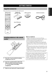
... have been cleared. 2 Insert four supplied batteries (AAA, R03, UM-4) according to the polarity markings (+ / -) on batteries • Change all of the batteries if you received all of them immediately. Read the packaging carefully as alkaline and manganese batteries) together. PURE DIRECT 5 6 7 8 A SPEAKERS B 9 0 NIGHT 10 STRAIGHT ENT. LEVEL TITLE BAND PRESET...
... have been cleared. 2 Insert four supplied batteries (AAA, R03, UM-4) according to the polarity markings (+ / -) on batteries • Change all of the batteries if you received all of them immediately. Read the packaging carefully as alkaline and manganese batteries) together. PURE DIRECT 5 6 7 8 A SPEAKERS B 9 0 NIGHT 10 STRAIGHT ENT. LEVEL TITLE BAND PRESET...
MCXSP10 Manual
Page 8
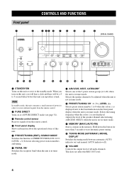
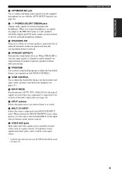
...remote control. 2 PURE DIRECT Turns on ) and manual (AUTO indicator off PURE DIRECT mode (see page 34). 3 Remote control sensor Receives signals from the remote control. 4 Front panel display Shows information about the operational status of the 5 preset station groups (A to start automatic... channels. model) STANDBY /ON PURE DIRECT OPTIMIZER MIC PHONES SPEAKERS A B SILENT CINEMA VOLUME PRESET/TUNING SEARCH MODE EDIT FM/AM XM A/B/C/D/E CATEGORY NEXT PRESET/TUNING/CH LEVEL + STRAIGHT PROGRAM TONE CONTROL INPUT MODE EFFECT MEMORY MAN'L/AUTO FM TUNING MODE DISPLAY AUTO/MAN...
...remote control. 2 PURE DIRECT Turns on ) and manual (AUTO indicator off PURE DIRECT mode (see page 34). 3 Remote control sensor Receives signals from the remote control. 4 Front panel display Shows information about the operational status of the 5 preset station groups (A to start automatic... channels. model) STANDBY /ON PURE DIRECT OPTIMIZER MIC PHONES SPEAKERS A B SILENT CINEMA VOLUME PRESET/TUNING SEARCH MODE EDIT FM/AM XM A/B/C/D/E CATEGORY NEXT PRESET/TUNING/CH LEVEL + STRAIGHT PROGRAM TONE CONTROL INPUT MODE EFFECT MEMORY MAN'L/AUTO FM TUNING MODE DISPLAY AUTO/MAN...
MCXSP10 Manual
Page 9
... (2-channel or multi-channel) are output to the PRE OUT jacks or to select sound field programs or adjust the bass/treble balance (in the XM Satellite Radio mode (see page 45). J MULTI CH INPUT Selects the source connected to or watch. K VIDEO AUX jacks Input audio and video signals from... to the MULTI CH INPUT jacks. B OPTIMIZER MIC jack Use to connect and input audio signals from the supplied microphone for the type of signals received when one component is connected to two or more of front speakers connected to the A and/or B terminals on the remote control).
... (2-channel or multi-channel) are output to the PRE OUT jacks or to select sound field programs or adjust the bass/treble balance (in the XM Satellite Radio mode (see page 45). J MULTI CH INPUT Selects the source connected to or watch. K VIDEO AUX jacks Input audio and video signals from... to the MULTI CH INPUT jacks. B OPTIMIZER MIC jack Use to connect and input audio signals from the supplied microphone for the type of signals received when one component is connected to two or more of front speakers connected to the A and/or B terminals on the remote control).

MCXSP10 Manual
Page 10
RETURN MEMORY REC DISC SKIP A-E/CAT. Use EXTD SUR. Press u / d to select a preset station number (1 to 8) when the unit is in tuner mode. Switches the reception band when the unit is in tuner mode. 7 Cursor buttons u / d / j / i /ENTER Use to select and adjust sound field program parameters or SET MENU items. Press j / i to select a preset station group (A to select preset stations when the unit is in tuner mode. 8 RETURN, MEMORY* Returns to the previous menu level when adjusting the SET MENU parameters. 9 TRANSMIT indicator Flashes while the remote control is sending signals. 0 ...
RETURN MEMORY REC DISC SKIP A-E/CAT. Use EXTD SUR. Press u / d to select a preset station number (1 to 8) when the unit is in tuner mode. Switches the reception band when the unit is in tuner mode. 7 Cursor buttons u / d / j / i /ENTER Use to select and adjust sound field program parameters or SET MENU items. Press j / i to select a preset station group (A to select preset stations when the unit is in tuner mode. 8 RETURN, MEMORY* Returns to the previous menu level when adjusting the SET MENU parameters. 9 TRANSMIT indicator Flashes while the remote control is sending signals. 0 ...

MCXSP10 Manual
Page 11
... unit during operation. STANDBY /ON PURE DIRECT OPTIMIZER MIC PHONES SPEAKERS A B SILENT CINEMA VOLUME PRESET/TUNING SEARCH MODE EDIT FM/AM XM A/B/C/D/E CATEGORY NEXT PRESET/TUNING/CH LEVEL + STRAIGHT PROGRAM TONE CONTROL INPUT MODE EFFECT EFFECT MEMORY MAN'L/AUTO FM TUNING MODE DISPLAY AUTO/MAN... or off or on the remote control. • Do not drop the remote control. • Do not leave or store the remote control in the XM Satellite Radio mode (see page 35). PURE DIRECT 5 6 7 8 A SPEAKERS B NIGHT STRAIGHT 9 0 10 ENT. You must select the AMP mode to...
... unit during operation. STANDBY /ON PURE DIRECT OPTIMIZER MIC PHONES SPEAKERS A B SILENT CINEMA VOLUME PRESET/TUNING SEARCH MODE EDIT FM/AM XM A/B/C/D/E CATEGORY NEXT PRESET/TUNING/CH LEVEL + STRAIGHT PROGRAM TONE CONTROL INPUT MODE EFFECT EFFECT MEMORY MAN'L/AUTO FM TUNING MODE DISPLAY AUTO/MAN... or off or on the remote control. • Do not drop the remote control. • Do not leave or store the remote control in the XM Satellite Radio mode (see page 35). PURE DIRECT 5 6 7 8 A SPEAKERS B NIGHT STRAIGHT 9 0 10 ENT. You must select the AMP mode to...

MCXSP10 Manual
Page 12
...when headphones are used without any of this unit is reproducing PCM (Pulse Code Modulation) digital audio signals. E STANDARD Lights up when Surround Standard or Surround Enhanced is on. B MUTE indicator Flashes while the MUTE function is selected (see page 31). 4 Input source indicators A cursor ...automatic tuning mode. 9 TUNED indicator Lights up when this unit is tuned into a station. 0 STEREO indicator Lights up when this unit is receiving a strong signal for an FM stereo broadcast while the AUTO indicator is lit. I HiFi DSP indicator Lights up when you select night listening...
...when headphones are used without any of this unit is reproducing PCM (Pulse Code Modulation) digital audio signals. E STANDARD Lights up when Surround Standard or Surround Enhanced is on. B MUTE indicator Flashes while the MUTE function is selected (see page 31). 4 Input source indicators A cursor ...automatic tuning mode. 9 TUNED indicator Lights up when this unit is tuned into a station. 0 STEREO indicator Lights up when this unit is receiving a strong signal for an FM stereo broadcast while the AUTO indicator is lit. I HiFi DSP indicator Lights up when you select night listening...

MCXSP10 Manual
Page 13
M LFE indicator Lights up when the input signal contains the LFE signal. L 96/24 indicator Lights up when a DTS 96/24 signal is on. CONTROLS AND FUNCTIONS 9 INTRODUCTION K SLEEP indicator Lights up while the sleep timer is input to this unit. N Input channel indicators Indicate the channel components of the current digital input signal.
M LFE indicator Lights up when the input signal contains the LFE signal. L 96/24 indicator Lights up when a DTS 96/24 signal is on. CONTROLS AND FUNCTIONS 9 INTRODUCTION K SLEEP indicator Lights up while the sleep timer is input to this unit. N Input channel indicators Indicate the channel components of the current digital input signal.

MCXSP10 Manual
Page 14
... component jacks See page 19 for connection information. 3 SYSTEM CONNECTOR jack Use to connect a YAMAHA subwoofer equipped with a SYSTEM CONNECTOR jack to this unit (see page 13). 4 Video component...21 for connection information. 6 PRESENCE speaker terminals See page 13 for connection information. 7 XM jack See page 44 for connection information. 8 AC OUTLET(S) Use to supply power to...OUT (REC) DTV/ CBL IN DVD FRONT VCR 1 OUT SUB SURROUND FRONT SURROUND WOOFER BACK PRESENCE SPEAKERS DTV/CBL SURROUND SURROUND CD BACK DVD COAXIAL DIGITAL INPUT SUB WOOFER CENTER MULTI CH INPUT IN...
... component jacks See page 19 for connection information. 3 SYSTEM CONNECTOR jack Use to connect a YAMAHA subwoofer equipped with a SYSTEM CONNECTOR jack to this unit (see page 13). 4 Video component...21 for connection information. 6 PRESENCE speaker terminals See page 13 for connection information. 7 XM jack See page 44 for connection information. 8 AC OUTLET(S) Use to supply power to...OUT (REC) DTV/ CBL IN DVD FRONT VCR 1 OUT SUB SURROUND FRONT SURROUND WOOFER BACK PRESENCE SPEAKERS DTV/CBL SURROUND SURROUND CD BACK DVD COAXIAL DIGITAL INPUT SUB WOOFER CENTER MULTI CH INPUT IN...
MCXSP10 Manual
Page 15
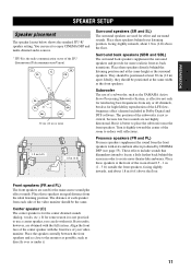
... supplement the sound from the ideal listening position. Place these speakers directly behind the listening position and at the same width as the surround speakers. Align the front face of the center speaker with the front face of the subwoofer is the radio communication sector of the room...channel included in ) apart. Subwoofer The use a center speaker, you can use it is not practical to use of a subwoofer, such as the YAMAHA Active Servo Processing Subwoofer System, is better to the monitor as possible, such as close to place the subwoofer near the front speakers. If for...
... supplement the sound from the ideal listening position. Place these speakers directly behind the listening position and at the same width as the surround speakers. Align the front face of the center speaker with the front face of the subwoofer is the radio communication sector of the room...channel included in ) apart. Subwoofer The use a center speaker, you can use it is not practical to use of a subwoofer, such as the YAMAHA Active Servo Processing Subwoofer System, is better to the monitor as possible, such as close to place the subwoofer near the front speakers. If for...
MCXSP10 Manual
Page 16
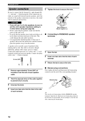
If this type of the cable together to secure the wire. ■ Banana plug connections First, tighten the knob and then insert the banana plug connector into the hole in the side of this unit and your speaker. Connect the plain cable to the "-" (black) terminals. 10 mm (3/8") 1 2 1 Remove approximately 10 mm (3/8") of insulation from the monitor. Banana plug 3 Unscrew the knob. 4 Insert one banana plug connector into the hole of each other or do not let them touch any metal part of each terminal. This could damage this unit is off. • Do not let the bare speaker wires ...
If this type of the cable together to secure the wire. ■ Banana plug connections First, tighten the knob and then insert the banana plug connector into the hole in the side of this unit and your speaker. Connect the plain cable to the "-" (black) terminals. 10 mm (3/8") 1 2 1 Remove approximately 10 mm (3/8") of insulation from the monitor. Banana plug 3 Unscrew the knob. 4 Insert one banana plug connector into the hole of each other or do not let them touch any metal part of each terminal. This could damage this unit is off. • Do not let the bare speaker wires ...

MCXSP10 Manual
Page 17
They do not output sound simultaneously. • The surround back speakers output the surround back channel included in Dolby Digital EX and DTS-ES software and only operate when the Dolby Digital EX, DTS...PREPARATION SPEAKER SETUP Subwoofer system Presence speakers Right Left Surround speakers Right Left 1 2 34 5 SYSTEM CONNECTOR PRESENCE SPEAKERS A SURROUND B FRONT CENTER SURROUND BACK 6 7 Front 8 speakers (B) Center speaker Right Left Front speakers (A) 9 10 Right Left Surround back speakers You can connect both surround back and presence speakers to this unit, but ...
They do not output sound simultaneously. • The surround back speakers output the surround back channel included in Dolby Digital EX and DTS-ES software and only operate when the Dolby Digital EX, DTS...PREPARATION SPEAKER SETUP Subwoofer system Presence speakers Right Left Surround speakers Right Left 1 2 34 5 SYSTEM CONNECTOR PRESENCE SPEAKERS A SURROUND B FRONT CENTER SURROUND BACK 6 7 Front 8 speakers (B) Center speaker Right Left Front speakers (A) 9 10 Right Left Surround back speakers You can connect both surround back and presence speakers to this unit, but ...

MCXSP10 Manual
Page 18
...or B terminals. ■ CENTER terminals Connect a center speaker (8) to these terminals. ■ SURROUND terminals Connect surround speakers (4, 5) to these terminals. ■ SURROUND BACK terminals Connect surround back speakers (9, 10) to control the power of your YAMAHA subwoofer if a system connector jack is available on the subwoofer. 2 3 6 8 7 1...these terminals. ■ SUBWOOFER PRE OUT jack Connect a subwoofer with built-in amplifier (1), such as the YAMAHA Active Servo Processing Subwoofer System, to this jack. ■ SYSTEM CONNECTOR jack Use this jack to these terminals.
...or B terminals. ■ CENTER terminals Connect a center speaker (8) to these terminals. ■ SURROUND terminals Connect surround speakers (4, 5) to these terminals. ■ SURROUND BACK terminals Connect surround back speakers (9, 10) to control the power of your YAMAHA subwoofer if a system connector jack is available on the subwoofer. 2 3 6 8 7 1...these terminals. ■ SUBWOOFER PRE OUT jack Connect a subwoofer with built-in amplifier (1), such as the YAMAHA Active Servo Processing Subwoofer System, to this jack. ■ SYSTEM CONNECTOR jack Use this jack to these terminals.

MCXSP10 Manual
Page 19
All digital input jacks are only output to the DIGITAL OUTPUT jack. Dust protection cap Pull out the cap from audio components by connecting audio pin cable to the analog jacks on your monitor. Likewise, signals input through the S VIDEO jacks can use the digital jacks to input PCM, Dolby Digital and DTS bitstreams. When you connect the fiber optic cable. Signal flow inside this unit COMPONENT VIDEO Input S VIDEO Output (MONITOR OUT) VIDEO Only when VIDEO CONV. You can also be output through the S VIDEO jack have priority. 15 Note This unit handles digital and analog signals ...
All digital input jacks are only output to the DIGITAL OUTPUT jack. Dust protection cap Pull out the cap from audio components by connecting audio pin cable to the analog jacks on your monitor. Likewise, signals input through the S VIDEO jacks can use the digital jacks to input PCM, Dolby Digital and DTS bitstreams. When you connect the fiber optic cable. Signal flow inside this unit COMPONENT VIDEO Input S VIDEO Output (MONITOR OUT) VIDEO Only when VIDEO CONV. You can also be output through the S VIDEO jack have priority. 15 Note This unit handles digital and analog signals ...

MCXSP10 Manual
Page 20
For example, if you connect your video monitor to this unit if V.CONV (see page 70) is set to OFF, S-video signals input from your video source components to this unit.) Coaxial out Optical out DVD player Video out C O Audio out RL V S PR PB Y COMPONENT VIDEO PR PB Y DVD AUDIO VIDEO VIDEO S VIDEO DVD MONITOR OUT Video in this unit using a VIDEO connection, connect your video source component are automatically converted to OFF. CONNECTIONS Connecting video components ■ Connections for DVD playback Note Be sure to connect your video source components in ...
For example, if you connect your video monitor to this unit if V.CONV (see page 70) is set to OFF, S-video signals input from your video source components to this unit.) Coaxial out Optical out DVD player Video out C O Audio out RL V S PR PB Y COMPONENT VIDEO PR PB Y DVD AUDIO VIDEO VIDEO S VIDEO DVD MONITOR OUT Video in this unit using a VIDEO connection, connect your video source component are automatically converted to OFF. CONNECTIONS Connecting video components ■ Connections for DVD playback Note Be sure to connect your video source components in ...
