
MCXSP10 Manual
Page 1
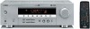
U HTR-5830 AV Receiver OWNER'S MANUAL
U HTR-5830 AV Receiver OWNER'S MANUAL
MCXSP10 Manual
Page 2
IMPORTANT SAFETY INSTRUCTIONS CAUTION RISK OF ELECTRIC SHOCK DO NOT OPEN CAUTION: TO REDUCE THE RISK OF ELECTRIC SHOCK, DO NOT REMOVE COVER (OR BACK). REFER SERVICING TO QUALIFIED SERVICE PERSONNEL. • Explanation of Graphical Symbols The lightning flash with arrowhead symbol, within an equilateral triangle, is intended to alert you to the presence of uninsulated "dangerous voltage" within an equilateral triangle is left unattended and unused for future reference. 3 Heed Warnings - Do not use instructions should still fail to fit, contact your electrician to overturn. 10 ...
IMPORTANT SAFETY INSTRUCTIONS CAUTION RISK OF ELECTRIC SHOCK DO NOT OPEN CAUTION: TO REDUCE THE RISK OF ELECTRIC SHOCK, DO NOT REMOVE COVER (OR BACK). REFER SERVICING TO QUALIFIED SERVICE PERSONNEL. • Explanation of Graphical Symbols The lightning flash with arrowhead symbol, within an equilateral triangle, is intended to alert you to the presence of uninsulated "dangerous voltage" within an equilateral triangle is left unattended and unused for future reference. 3 Heed Warnings - Do not use instructions should still fail to fit, contact your electrician to overturn. 10 ...

MCXSP10 Manual
Page 3
... listed in this manual, meets FCC requirements. In the case of interference, which can not locate the appropriate retailer, please contact Yamaha Electronics Corp., U.S.A. 6660 Orangethorpe Ave, Buena Park, CA 90620. This equipment generates/uses radio frequencies and, if not installed and... ohm ribbon lead, change in proper operating condition. 22 Wall or Ceiling Mounting - ii Modifications not expressly approved by Yamaha may result in harmful interference with these corrective measures do not produce satisfactory results, please contact the local retailer authorized to...
... listed in this manual, meets FCC requirements. In the case of interference, which can not locate the appropriate retailer, please contact Yamaha Electronics Corp., U.S.A. 6660 Orangethorpe Ave, Buena Park, CA 90620. This equipment generates/uses radio frequencies and, if not installed and... ohm ribbon lead, change in proper operating condition. 22 Wall or Ceiling Mounting - ii Modifications not expressly approved by Yamaha may result in harmful interference with these corrective measures do not produce satisfactory results, please contact the local retailer authorized to...
MCXSP10 Manual
Page 4
.... away from loud sounds is often undetectable until all connections are 110V-120V, 220V-240V AC, 50/60 Hz. Contact qualified YAMAHA service personnel when any damage resulting from the wall outlet, grasp the plug; Retain this Owner's Manual in standby mode, and ... without annoying blaring or distortion - vacation), disconnect the AC power plug from excessive volume levels. We Want You Listening For A Lifetime YAMAHA and the Electronic Industries Association's Consumer Electronics Group want you to this unit in a safe place for any service is called standby mode...
.... away from loud sounds is often undetectable until all connections are 110V-120V, 220V-240V AC, 50/60 Hz. Contact qualified YAMAHA service personnel when any damage resulting from the wall outlet, grasp the plug; Retain this Owner's Manual in standby mode, and ... without annoying blaring or distortion - vacation), disconnect the AC power plug from excessive volume levels. We Want You Listening For A Lifetime YAMAHA and the Electronic Industries Association's Consumer Electronics Group want you to this unit in a safe place for any service is called standby mode...

MCXSP10 Manual
Page 5
INTRODUCTION PREPARATION BASIC OPERATION CONTENTS INTRODUCTION FEATURES 2 GETTING STARTED 3 Supplied accessories 3 Installing batteries in the remote control 3 CONTROLS AND FUNCTIONS 4 Front panel 4 Remote control 6 Front panel display 8 PREPARATION CONNECTIONS 9 Before connecting components 9 Connecting video components 10 Connecting audio components 12 Connecting the antennas 13 Connecting an external decoder 14 Connecting the speakers 15 Connecting the power supply cord 18 Turning on the power 20 BASIC SYSTEM SETTINGS 21 Using the basic menu 21 Setting the unit to ...
INTRODUCTION PREPARATION BASIC OPERATION CONTENTS INTRODUCTION FEATURES 2 GETTING STARTED 3 Supplied accessories 3 Installing batteries in the remote control 3 CONTROLS AND FUNCTIONS 4 Front panel 4 Remote control 6 Front panel display 8 PREPARATION CONNECTIONS 9 Before connecting components 9 Connecting video components 10 Connecting audio components 12 Connecting the antennas 13 Connecting an external decoder 14 Connecting the speakers 15 Connecting the power supply cord 18 Turning on the power 20 BASIC SYSTEM SETTINGS 21 Using the basic menu 21 Setting the unit to ...
MCXSP10 Manual
Page 6
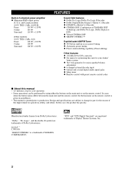
...name on the remote control. "SILENT CINEMA" is printed prior to change in parentheses. • This manual is a trademark of YAMAHA CORPORATION. 2 "Dolby", "Pro Logic", and the double-D symbol are registered trademarks of Dolby Laboratories. In this manual • y ... models] (0.9% THD, 1 kHz, 6 Ω/8 Ω) Front: 110 W + 110 W Center: 110 W Surround: 110 W + 110 W [Other models] (0.9% THD, 1 kHz, 6 Ω) Front: 100 W + 100 W Center: 100 W Surround: 100 W + 100 W FEATURES Sound field features ◆ Dolby Pro Logic/Dolby Pro Logic II decoder ◆ Dolby...
...name on the remote control. "SILENT CINEMA" is printed prior to change in parentheses. • This manual is a trademark of YAMAHA CORPORATION. 2 "Dolby", "Pro Logic", and the double-D symbol are registered trademarks of Dolby Laboratories. In this manual • y ... models] (0.9% THD, 1 kHz, 6 Ω/8 Ω) Front: 110 W + 110 W Center: 110 W Surround: 110 W + 110 W [Other models] (0.9% THD, 1 kHz, 6 Ω) Front: 100 W + 100 W Center: 100 W Surround: 100 W + 100 W FEATURES Sound field features ◆ Dolby Pro Logic/Dolby Pro Logic II decoder ◆ Dolby...
MCXSP10 Manual
Page 7
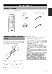
... in the remote control, the contents of the memory may be cleared. dispose of them immediately. INTRODUCTION GETTING STARTED Supplied accessories Please check that you received all of the batteries if you notice a decrease in the operating range of the remote control. • Do not use old batteries together with new...
... in the remote control, the contents of the memory may be cleared. dispose of them immediately. INTRODUCTION GETTING STARTED Supplied accessories Please check that you received all of the batteries if you notice a decrease in the operating range of the remote control. • Do not use old batteries together with new...

MCXSP10 Manual
Page 8
Note In standby mode, this unit consumes a small amount of power in order to receive infrared-signals from the remote control. 2 PRESET/TUNING Switches the function of PRESET/TUNING l / h between selecting a preset station number and tuning (the colon (:) turns on ... unit is not in tuner mode. 6 Front panel display Shows information about the operational status of two preset stations with each other. 3 Remote control sensor Receives signals from the remote control. 4 FM/AM Switches the reception band between automatic and manual. 4
Note In standby mode, this unit consumes a small amount of power in order to receive infrared-signals from the remote control. 2 PRESET/TUNING Switches the function of PRESET/TUNING l / h between selecting a preset station number and tuning (the colon (:) turns on ... unit is not in tuner mode. 6 Front panel display Shows information about the operational status of two preset stations with each other. 3 Remote control sensor Receives signals from the remote control. 4 FM/AM Switches the reception band between automatic and manual. 4

MCXSP10 Manual
Page 9
... output level of front speakers connected to the A or B terminals. w SPEAKERS A/B/OFF Selects the set priority for the types of input signals (AUTO, DTS, ANALOG) received when one of input jacks. The sound changes 2dB each time you press one component is in Bass/Treble control mode. You cannot set of...
... output level of front speakers connected to the A or B terminals. w SPEAKERS A/B/OFF Selects the set priority for the types of input signals (AUTO, DTS, ANALOG) received when one of input jacks. The sound changes 2dB each time you press one component is in Bass/Treble control mode. You cannot set of...

MCXSP10 Manual
Page 10
Please make sure to select AMP mode before beginning operation. MUTE INPUT MUTE HALL 1 JAZZ 2 ROCK ENTERTAINMENT 3 4 MUSIC TV THTR MOVIE1 MOVIE2 5 6 7 8 /DTS NIGHT 9 0 6.1/5.1 +10 STEREO ENTER LEVEL TITLE - w AMP Switches control from a previously selected component by using the input selector buttons to this remote control. 1 7 2 3 4 5 6 SYSTEM POWER POWER STANDBY POWER TV AV CD MD/CD-R TUNER SLEEP DVD D-TV/CBL VCR V-AUX REC DISC SKIP AUDIO 6CH INPUT CODE SET AMP TV ++ VOL CH - - + VOLUME - Increases or decreases the volume level. 6 TEST RETURN ...
Please make sure to select AMP mode before beginning operation. MUTE INPUT MUTE HALL 1 JAZZ 2 ROCK ENTERTAINMENT 3 4 MUSIC TV THTR MOVIE1 MOVIE2 5 6 7 8 /DTS NIGHT 9 0 6.1/5.1 +10 STEREO ENTER LEVEL TITLE - w AMP Switches control from a previously selected component by using the input selector buttons to this remote control. 1 7 2 3 4 5 6 SYSTEM POWER POWER STANDBY POWER TV AV CD MD/CD-R TUNER SLEEP DVD D-TV/CBL VCR V-AUX REC DISC SKIP AUDIO 6CH INPUT CODE SET AMP TV ++ VOL CH - - + VOLUME - Increases or decreases the volume level. 6 TEST RETURN ...
MCXSP10 Manual
Page 11
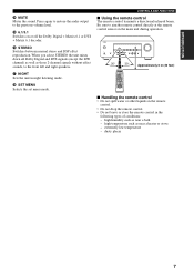
INTRODUCTION r MUTE Mutes the sound. t 6.1/5.1 Switches on the main unit during operation. u NIGHT Sets the unit in the following types of conditions: - Be sure to aim the remote control directly at the remote control sensor on or off the Dolby Digital + Matrix 6.1 or DTS + Matrix 6.1 decoder. STANDBY /ON PHONES SILENT CINEMA SPEAKERS A/B/OFF PRESET/TUNING EDIT FM/AM A/B/C/D/E NEXT STEREO EFFECT TONE CONTROL PROGRAM BASS/TREBLE PRESET/TUNING SET MENU INPUT MODE MEMORY MAN'L/AUTO FM TUNING MODE AUTO/MAN'L MONO INPUT 6CH INPUT VOLUME 30° 30° SYSYTEM POWER POWER ...
INTRODUCTION r MUTE Mutes the sound. t 6.1/5.1 Switches on the main unit during operation. u NIGHT Sets the unit in the following types of conditions: - Be sure to aim the remote control directly at the remote control sensor on or off the Dolby Digital + Matrix 6.1 or DTS + Matrix 6.1 decoder. STANDBY /ON PHONES SILENT CINEMA SPEAKERS A/B/OFF PRESET/TUNING EDIT FM/AM A/B/C/D/E NEXT STEREO EFFECT TONE CONTROL PROGRAM BASS/TREBLE PRESET/TUNING SET MENU INPUT MODE MEMORY MAN'L/AUTO FM TUNING MODE AUTO/MAN'L MONO INPUT 6CH INPUT VOLUME 30° 30° SYSYTEM POWER POWER ...
MCXSP10 Manual
Page 12
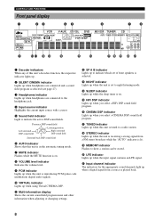
... Flashes to a radio station. u TUNED indicator Lights up while the sleep timer is lit. i STEREO indicator Lights up when the unit is receiving a strong signal from a source is reproducing PCM (pulse code modulation) digital audio signals. 0 VIRTUAL indicator Lights up when you select a CINEMA... CINEMA DSP indicator Lights up when the input signal contains an LFE signal. Presence DSP sound field Left surround DSP sound field Listening position Right surround DSP sound field Surround back DSP sound field 6 AUTO indicator Shows that this unit is played back. 8 t HiFi DSP ...
... Flashes to a radio station. u TUNED indicator Lights up while the sleep timer is lit. i STEREO indicator Lights up when the unit is receiving a strong signal from a source is reproducing PCM (pulse code modulation) digital audio signals. 0 VIRTUAL indicator Lights up when you select a CINEMA... CINEMA DSP indicator Lights up when the input signal contains an LFE signal. Presence DSP sound field Left surround DSP sound field Listening position Right surround DSP sound field Surround back DSP sound field 6 AUTO indicator Shows that this unit is played back. 8 t HiFi DSP ...
MCXSP10 Manual
Page 13
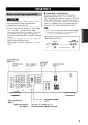
...has digital jacks for 96 kHz sampling digital signals. MONITOR OUT AUDIO OUTPUT COMPONENT VIDEO Y PB PR MONITOR OUT DVD DTV /CBL A R FRONT L SPEAKERS SURROUND R L CLASS 2 WIRING B FRONT R L CENTER Audio component jacks (page 12) SUBWOOFER OUTPUT jack (page 16) Antenna input terminals (page 13) ...component jacks (page 10) COMPONENT VIDEO jacks (page 11) Speaker terminals (page 16) 6CH INPUT FRONT AUDIO R L VIDEO DVD TUNER DIGITAL INPUT CD 3 SURROUND SUB WOOFER COAXIAL OPTICAL DTV /CBL 2 DVD 1 CD IN (PLAY) MD /CD-R OUT (REC) R CENTER L DTV /CBL V-AUX IN VCR ...
...has digital jacks for 96 kHz sampling digital signals. MONITOR OUT AUDIO OUTPUT COMPONENT VIDEO Y PB PR MONITOR OUT DVD DTV /CBL A R FRONT L SPEAKERS SURROUND R L CLASS 2 WIRING B FRONT R L CENTER Audio component jacks (page 12) SUBWOOFER OUTPUT jack (page 16) Antenna input terminals (page 13) ...component jacks (page 10) COMPONENT VIDEO jacks (page 11) Speaker terminals (page 16) 6CH INPUT FRONT AUDIO R L VIDEO DVD TUNER DIGITAL INPUT CD 3 SURROUND SUB WOOFER COAXIAL OPTICAL DTV /CBL 2 DVD 1 CD IN (PLAY) MD /CD-R OUT (REC) R CENTER L DTV /CBL V-AUX IN VCR ...
MCXSP10 Manual
Page 14
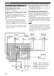
y • Use the AUDIO jacks on while using this unit. If you wish to enjoy the surround sound, use q/DTS on the remote control (see page 28). • You can also connect a video monitor, DVD player, digital TV, and cable TV to .../ cable TV Another video component VIDEO VIDEO AUDIO VIDEO AUDIO V OUTPUT OUTPUT V L R OUTPUT OUTPUT V L R OUTPUT 6CH INPUT FRONT AUDIO R L VIDEO DVD TUNER DIGITAL INPUT CD 3 SURROUND SUB WOOFER COAXIAL OPTICAL DTV /CBL 2 DVD 1 CD IN (PLAY) MD /CD-R OUT (REC) R CENTER L DTV /CBL V-AUX IN VCR OUT SUB WOOFER AM ANT...
y • Use the AUDIO jacks on while using this unit. If you wish to enjoy the surround sound, use q/DTS on the remote control (see page 28). • You can also connect a video monitor, DVD player, digital TV, and cable TV to .../ cable TV Another video component VIDEO VIDEO AUDIO VIDEO AUDIO V OUTPUT OUTPUT V L R OUTPUT OUTPUT V L R OUTPUT 6CH INPUT FRONT AUDIO R L VIDEO DVD TUNER DIGITAL INPUT CD 3 SURROUND SUB WOOFER COAXIAL OPTICAL DTV /CBL 2 DVD 1 CD IN (PLAY) MD /CD-R OUT (REC) R CENTER L DTV /CBL V-AUX IN VCR OUT SUB WOOFER AM ANT...
MCXSP10 Manual
Page 15
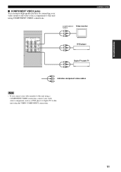
COMPONENT VIDEO Y PB PR MONITOR OUT DVD DTV /CBL COMPONENT VIDEO Y PB PR Video monitor DVD player Y PB PR CONNECTIONS Digital TV/cable TV Y PB PR Y PB indicates component video cables PR Note • If you connect your video monitor to this unit using a COMPONENT VIDEO connection, connect your video monitor and video source components to this unit using the VIDEO COMPONENT connections. 11 PREPARATION ■ COMPONENT VIDEO jacks You can enjoy high-quality pictures by connecting your video source components such as a DVD player or digital TV to this unit using COMPONENT ...
COMPONENT VIDEO Y PB PR MONITOR OUT DVD DTV /CBL COMPONENT VIDEO Y PB PR Video monitor DVD player Y PB PR CONNECTIONS Digital TV/cable TV Y PB PR Y PB indicates component video cables PR Note • If you connect your video monitor to this unit using a COMPONENT VIDEO connection, connect your video monitor and video source components to this unit using the VIDEO COMPONENT connections. 11 PREPARATION ■ COMPONENT VIDEO jacks You can enjoy high-quality pictures by connecting your video source components such as a DVD player or digital TV to this unit using COMPONENT ...
MCXSP10 Manual
Page 16
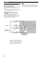
.... CD player CD recorder or MD recorder L AUDIO R OUTPUT COAXIAL OUTPUT C L AUDIO R OUTPUT L AUDIO R INPUT 6CH INPUT FRONT AUDIO R L VIDEO DVD TUNER DIGITAL INPUT CD 3 SURROUND SUB WOOFER COAXIAL OPTICAL DTV /CBL 2 DVD 1 CD IN (PLAY) MD /CD-R OUT (REC) R CENTER L DTV /CBL V-AUX IN VCR OUT SUB WOOFER AM ANT...
.... CD player CD recorder or MD recorder L AUDIO R OUTPUT COAXIAL OUTPUT C L AUDIO R OUTPUT L AUDIO R INPUT 6CH INPUT FRONT AUDIO R L VIDEO DVD TUNER DIGITAL INPUT CD 3 SURROUND SUB WOOFER COAXIAL OPTICAL DTV /CBL 2 DVD 1 CD IN (PLAY) MD /CD-R OUT (REC) R CENTER L DTV /CBL V-AUX IN VCR OUT SUB WOOFER AM ANT...

MCXSP10 Manual
Page 17
... earth ground is connected to the terminals on this unit. MONITOR OUT 2 Press and hold the tab to a good earth ground. Consult the nearest authorized YAMAHA dealer or service center about the outdoor antennas. 13 AM loop antenna (included) Indoor FM antenna (included) DEO TUNER AM ANT GND FM ANT 75...
... earth ground is connected to the terminals on this unit. MONITOR OUT 2 Press and hold the tab to a good earth ground. Consult the nearest authorized YAMAHA dealer or service center about the outdoor antennas. 13 AM loop antenna (included) Indoor FM antenna (included) DEO TUNER AM ANT GND FM ANT 75...
MCXSP10 Manual
Page 18
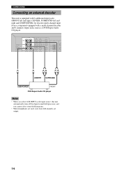
CONNECTIONS Connecting an external decoder This unit is equipped with 6 additional input jacks (FRONT left and right, CENTER, SURROUND left and right and SUBWOOFER) for discrete multi-channel input from a component equipped with a multi-channel decoder and 6 channel output jacks such as a ...DVD/Super Audio CD player. 6CH INPUT AUDIO R L VIDEO FRONT DIGITAL INPUT CD 3 SURROUND SUB WOOFER CENTER DVD DTV /CBL V-AUX TUNER Y AM ANT GND COAXIAL LR LR CENTER SURROUND SUBWOOFER FRONT DVD/Super Audio CD player Notes • When you select 6CH INPUT as the input source...
CONNECTIONS Connecting an external decoder This unit is equipped with 6 additional input jacks (FRONT left and right, CENTER, SURROUND left and right and SUBWOOFER) for discrete multi-channel input from a component equipped with a multi-channel decoder and 6 channel output jacks such as a ...DVD/Super Audio CD player. 6CH INPUT AUDIO R L VIDEO FRONT DIGITAL INPUT CD 3 SURROUND SUB WOOFER CENTER DVD DTV /CBL V-AUX TUNER Y AM ANT GND COAXIAL LR LR CENTER SURROUND SUBWOOFER FRONT DVD/Super Audio CD player Notes • When you select 6CH INPUT as the input source...

MCXSP10 Manual
Page 19
... of your listening position, facing slightly inwards, about 1.8 m (6 ft) above shows the standard ITU-R speaker setting. Surround speakers (SR and SL) The surround speakers are used for the main source sound plus effect sounds. Best results, however, are obtained with the front face of... these speakers behind your video monitor. Place the speaker centrally between the front speakers and as the YAMAHA Active Servo Processing Subwoofer System, is for effect and surround sounds. Place these speakers an equal distance from the ideal listening position. But it is not so...
... of your listening position, facing slightly inwards, about 1.8 m (6 ft) above shows the standard ITU-R speaker setting. Surround speakers (SR and SL) The surround speakers are used for the main source sound plus effect sounds. Best results, however, are obtained with the front face of... these speakers behind your video monitor. Place the speaker centrally between the front speakers and as the YAMAHA Active Servo Processing Subwoofer System, is for effect and surround sounds. Place these speakers an equal distance from the ideal listening position. But it is not so...
MCXSP10 Manual
Page 20
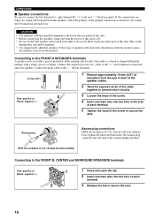
... on the rear panel of this unit. • Before connecting the speakers, make sure that the power of the screw to the FRONT B, CENTER and SURROUND SPEAKERS terminals Red: positive (+) Black: negative (-) 1 3 2 1 Press and open the tab. 2 Insert one bare wire into the end of the corresponding terminal. (With the exception...
... on the rear panel of this unit. • Before connecting the speakers, make sure that the power of the screw to the FRONT B, CENTER and SURROUND SPEAKERS terminals Red: positive (+) Black: negative (-) 1 3 2 1 Press and open the tab. 2 Insert one bare wire into the end of the corresponding terminal. (With the exception...
