
Owner's Manual
Page 2
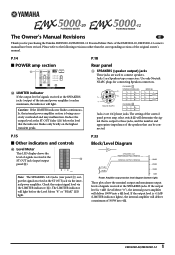
... the LIMITER indicator flashes continuously, the internal power amplifier section is +11dB (LIMITER indicator lights), the internal amplifier will deliver 100W into 4Ω. 1 EMX5000-20/EMX5000-12 A- 1+ 2+ B+ 2- BRIDGE 1+ + 1- 2+ - 2- If the output level is output to connect speakers. Parts of the original owner's manual. P.18 Rear panel... and appropriate impedance of signals received at the SPEAKERS jacks. Use only Neutrik NL4FC plugs for purchasing the Yamaha EMX5000-20/EMX5000-12 Powered Mixer. The LIMITER indicator will light.
... the LIMITER indicator flashes continuously, the internal power amplifier section is +11dB (LIMITER indicator lights), the internal amplifier will deliver 100W into 4Ω. 1 EMX5000-20/EMX5000-12 A- 1+ 2+ B+ 2- BRIDGE 1+ + 1- 2+ - 2- If the output level is output to connect speakers. Parts of the original owner's manual. P.18 Rear panel... and appropriate impedance of signals received at the SPEAKERS jacks. Use only Neutrik NL4FC plugs for purchasing the Yamaha EMX5000-20/EMX5000-12 Powered Mixer. The LIMITER indicator will light.
Owner's Manual
Page 3
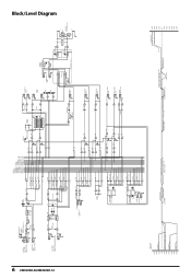
... AFL R 63Hz 125Hz 250Hz 500Hz 1kHz 2kHz 4kHz 8kHz 16kHz Block/Level Diagram 6 EMX5000-20/EMX5000-12 CH INPUT A [-60~-16dB] [-34~+10dB] EMX5000-12:CH1-8 EMX5000-20:CH1-16 B CH INSERT I/O [0dB] EMX5000-12:CH1-8 EMX5000-20:CH1-16 +48V PHANTOM 8CH/SW EMX5000-12:[CH1-8] EMX5000-20:[CH1-8] [CH9-16] PAD HA [0dB] 26dB GAIN [-60~-16dB] [-34~+...SUB OUT [+4dB] R L ST OUT [+4dB] R PEAK DR PEAK DR MONO OUT [+4dB] A POWER AMP IN [+4dB] B YAMAHA SPEAKER PROCESSING YSP YSP MAIN L AUX1 AUX1 MONO BRIDGE INV Signal Select MAIN R MONO AUX2 MONO BRIDGE POWER AMP Controls LIMITTER 500W 300W 100W...
... AFL R 63Hz 125Hz 250Hz 500Hz 1kHz 2kHz 4kHz 8kHz 16kHz Block/Level Diagram 6 EMX5000-20/EMX5000-12 CH INPUT A [-60~-16dB] [-34~+10dB] EMX5000-12:CH1-8 EMX5000-20:CH1-16 B CH INSERT I/O [0dB] EMX5000-12:CH1-8 EMX5000-20:CH1-16 +48V PHANTOM 8CH/SW EMX5000-12:[CH1-8] EMX5000-20:[CH1-8] [CH9-16] PAD HA [0dB] 26dB GAIN [-60~-16dB] [-34~+...SUB OUT [+4dB] R L ST OUT [+4dB] R PEAK DR PEAK DR MONO OUT [+4dB] A POWER AMP IN [+4dB] B YAMAHA SPEAKER PROCESSING YSP YSP MAIN L AUX1 AUX1 MONO BRIDGE INV Signal Select MAIN R MONO AUX2 MONO BRIDGE POWER AMP Controls LIMITTER 500W 300W 100W...
Owner's Manual
Page 5
..., etc. - Locations exposed to amplifier outputs. Never pull the cord. Doing so is turned off , remove the power plug from the AC outlet. EMX5000-20/EMX5000-12-Owner's Manual
..., etc. - Locations exposed to amplifier outputs. Never pull the cord. Doing so is turned off , remove the power plug from the AC outlet. EMX5000-20/EMX5000-12-Owner's Manual
Owner's Manual
Page 6
... induce a slight noise into nearby radios and TVs. If noise occurs, use the telephone away from the unit. If noise occurs, relocate the affected equipment. EMX5000-20/EMX5000-12-Owner's Manual FOR CORRECT OPERATION - Influence on cell phone usage • Using a cell phone (mobile telephone) near this unit may damage the speakers. The rate...
... induce a slight noise into nearby radios and TVs. If noise occurs, use the telephone away from the unit. If noise occurs, relocate the affected equipment. EMX5000-20/EMX5000-12-Owner's Manual FOR CORRECT OPERATION - Influence on cell phone usage • Using a cell phone (mobile telephone) near this unit may damage the speakers. The rate...
Owner's Manual
Page 7
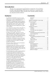
... by adding a power amplifier or powered speakers. • The EMX5000-20/EMX5000-12 also has a PHONES jack, which lets you easily adjust the delay time. • The EMX5000-20/EMX5000-12 has implemented "EEEngine", Yamaha's epochal amp drive technology to a reduction in . Introduction 5 Introduction Thank ...A maximum output select switch lets you switch the maximum output of effect equivalent in a safe place for purchasing the Yamaha EMX5000-20/EMX5000-12 Powered Mixer. The effects can easily expand the system by each providing sixteen types of the amp between three levels. ...
... by adding a power amplifier or powered speakers. • The EMX5000-20/EMX5000-12 also has a PHONES jack, which lets you easily adjust the delay time. • The EMX5000-20/EMX5000-12 has implemented "EEEngine", Yamaha's epochal amp drive technology to a reduction in . Introduction 5 Introduction Thank ...A maximum output select switch lets you switch the maximum output of effect equivalent in a safe place for purchasing the Yamaha EMX5000-20/EMX5000-12 Powered Mixer. The effects can easily expand the system by each providing sixteen types of the amp between three levels. ...
Owner's Manual
Page 8
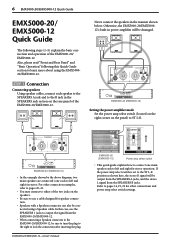
...EMX5000-20/EMX5000-12-Owner's Manual EMX5000-20 (EMX5000-12) Power amp select switch • This quick guide explains how to connect one each to pages 14, 19, 20 for speaker connection. • Speakers with a Speakon connector can also be connected using the EMX500020/EMX5000-12. Refer to left and right) in the manner shown below. 6 EMX5000-20/EMX5000-12 Quick Guide EMX5000-20/ EMX5000-12...use the SPEAKERS 1 jacks to output the signal from the EMX5000-20/EMX5000-12. • When connecting a Speakon connector to the EMX5000-20/EMX5000-12, be sure to turn the plug to the right to...
...EMX5000-20/EMX5000-12-Owner's Manual EMX5000-20 (EMX5000-12) Power amp select switch • This quick guide explains how to connect one each to pages 14, 19, 20 for speaker connection. • Speakers with a Speakon connector can also be connected using the EMX500020/EMX5000-12. Refer to left and right) in the manner shown below. 6 EMX5000-20/EMX5000-12 Quick Guide EMX5000-20/ EMX5000-12...use the SPEAKERS 1 jacks to output the signal from the EMX5000-20/EMX5000-12. • When connecting a Speakon connector to the EMX5000-20/EMX5000-12, be sure to turn the plug to the right to...
Owner's Manual
Page 9
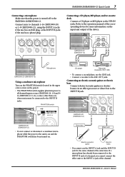
... condenser mics must be connected to the INPUT A jack of the device. EMX5000-20 (EMX5000-12) Microphone EMX5000-20 (EMX5000-12) Using a condenser microphone Turn on the PHANTOM switch (located in the upper center corner on the panel). • The PHANTOM switch supplies phantom power to the EMX5000-20/EMX5000-12. EMX5000-20 (EMX5000-12) • Do not connect or disconnect a condenser microphone while the power...
... condenser mics must be connected to the INPUT A jack of the device. EMX5000-20 (EMX5000-12) Microphone EMX5000-20 (EMX5000-12) Using a condenser microphone Turn on the PHANTOM switch (located in the upper center corner on the panel). • The PHANTOM switch supplies phantom power to the EMX5000-20/EMX5000-12. EMX5000-20 (EMX5000-12) • Do not connect or disconnect a condenser microphone while the power...
Owner's Manual
Page 10
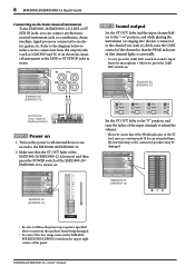
... power to all external devices connected to the EMX5000-20/EMX5000-12. 2 Make sure that the ST OUT fader of the EMX5000-20/EMX5000-12 is lowered, and then press the POWER switch of the EMX5000-20/ EMX5000-12 to prevent the speakers from the microphone. Otherwise, press the 26dB PAD switch on the YAMAHA SPEAKER PROCESSING switch in stereo. STEP 3 Sound output...
... power to all external devices connected to the EMX5000-20/EMX5000-12. 2 Make sure that the ST OUT fader of the EMX5000-20/EMX5000-12 is lowered, and then press the POWER switch of the EMX5000-20/ EMX5000-12 to prevent the speakers from the microphone. Otherwise, press the 26dB PAD switch on the YAMAHA SPEAKER PROCESSING switch in stereo. STEP 3 Sound output...
Owner's Manual
Page 11
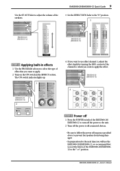
The ON switch indicator lights up. 1 EMX5000-20 (EMX5000-12) 2 4 If you want to use the EMX5000-20/EMX5000-12, we recommend that you want to apply the effect. EMX5000-20/EMX5000-12 Quick Guide 9 Use the ST OUT fader to adjust the volume of the speakers. 3 Set the EFFECT RTN fader to the "0" position. 3 EMX5000-20 (EMX5000-12) EMX5000-20 (EMX5000-12) STEP 4 Applying built-in effects 1 Use the PROGRAM...
The ON switch indicator lights up. 1 EMX5000-20 (EMX5000-12) 2 4 If you want to use the EMX5000-20/EMX5000-12, we recommend that you want to apply the effect. EMX5000-20/EMX5000-12 Quick Guide 9 Use the ST OUT fader to adjust the volume of the speakers. 3 Set the EFFECT RTN fader to the "0" position. 3 EMX5000-20 (EMX5000-12) EMX5000-20 (EMX5000-12) STEP 4 Applying built-in effects 1 Use the PROGRAM...
Owner's Manual
Page 12
... are as follows: HIGH: 10kHz, ±15 dB, shelving type MID: 250Hz-5kHz, ±15 dB, peaking type LOW: 100Hz, ±15 dB, shelving type EMX5000-20/EMX5000-12-Owner's Manual For the mid range, use the upper MID knob to specify the center frequency of the range, and use the lower knob to...
... are as follows: HIGH: 10kHz, ±15 dB, shelving type MID: 250Hz-5kHz, ±15 dB, peaking type LOW: 100Hz, ±15 dB, shelving type EMX5000-20/EMX5000-12-Owner's Manual For the mid range, use the upper MID knob to specify the center frequency of the range, and use the lower knob to...
Owner's Manual
Page 13
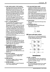
...at R, and at left at L. 8 BAL (balance) control (EMX5000-20: Channels 17/18-19/20, EMX5000-12: Channels 9/10-11/12) The BAL knobs set by the setting of the channel fader C (post-fader send). 7 PAN (panpot) control (EMX5000-20: Channels 1-16, EMX5000-12: Channels 1-8) The PAN knobs set to the "√" position. ... sent to the AUX1 and 2 buses. C Channel fader This controls the output level of stereo signal sent from each channel. EMX5000-20/EMX5000-12-Owner's Manual F ST (stereo) control The ST knob adjusts the amount of the input channel signal. The indicator will light...
...at R, and at left at L. 8 BAL (balance) control (EMX5000-20: Channels 17/18-19/20, EMX5000-12: Channels 9/10-11/12) The BAL knobs set by the setting of the channel fader C (post-fader send). 7 PAN (panpot) control (EMX5000-20: Channels 1-16, EMX5000-12: Channels 1-8) The PAN knobs set to the "√" position. ... sent to the AUX1 and 2 buses. C Channel fader This controls the output level of stereo signal sent from each channel. EMX5000-20/EMX5000-12-Owner's Manual F ST (stereo) control The ST knob adjusts the amount of the input channel signal. The indicator will light...
Owner's Manual
Page 14
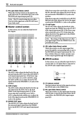
... outputs. I J K H AUX 1 fader The AUX 1 fader adjusts the final level of the signal sent from the SPEAKERS A 1 jacks to the speaker. EMX5000-20/EMX5000-12-Owner's Manual If the Power amp select switch Y is set to ST L-R, this switch is on, the output signal that is connected to the 2TR... In this section, you wish to monitor a particular output signal through the corresponding fader is sent to the PHONES jack (input/output panel D). 12 Front and rear panel G PFL (pre-fader listen) switch When this switch is turned on, the signal at the point before the ST control...
... outputs. I J K H AUX 1 fader The AUX 1 fader adjusts the final level of the signal sent from the SPEAKERS A 1 jacks to the speaker. EMX5000-20/EMX5000-12-Owner's Manual If the Power amp select switch Y is set to ST L-R, this switch is on, the output signal that is connected to the 2TR... In this section, you wish to monitor a particular output signal through the corresponding fader is sent to the PHONES jack (input/output panel D). 12 Front and rear panel G PFL (pre-fader listen) switch When this switch is turned on, the signal at the point before the ST control...
Owner's Manual
Page 15
... set the desired delay time. T PFL (Pre-fader listen) switch When this switch to set as the internal effect type, you to the AUX 1/2 buses. U U EMX5000-20/EMX5000-12-Owner's Manual P PARAMETER control This knob adjusts the time parameter of the internal digital effect. S EFFECT 1/2 ON switch This switch turns the internal digital effect...
... set the desired delay time. T PFL (Pre-fader listen) switch When this switch to set as the internal effect type, you to the AUX 1/2 buses. U U EMX5000-20/EMX5000-12-Owner's Manual P PARAMETER control This knob adjusts the time parameter of the internal digital effect. S EFFECT 1/2 ON switch This switch turns the internal digital effect...
Owner's Manual
Page 16
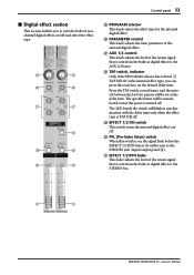
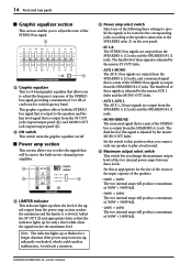
...these signals is adjusted by the master ST OUT fader. • AUX 1-MONO The AUX 1 bus signals are output from the SPEAKERS B 1/2 jacks. EMX5000-20/EMX5000-12-Owner's Manual s Power amp section This section allows you to select the signals that is a mix of the STEREO bus is activated. Set the switch... panel s Graphic equalizer section This section enables you to adjust the frequency response of the STEREO bus signal, providing a maximum of ±12 dB of cut/boost for each frequency band. This graphic equalizer affects both the STEREO bus signal that is output to the speakers and the...
...these signals is adjusted by the master ST OUT fader. • AUX 1-MONO The AUX 1 bus signals are output from the SPEAKERS B 1/2 jacks. EMX5000-20/EMX5000-12-Owner's Manual s Power amp section This section allows you to select the signals that is a mix of the STEREO bus is activated. Set the switch... panel s Graphic equalizer section This section enables you to adjust the frequency response of the STEREO bus signal, providing a maximum of ±12 dB of cut/boost for each frequency band. This graphic equalizer affects both the STEREO bus signal that is output to the speakers and the...
Owner's Manual
Page 17
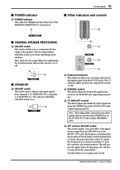
... bus to on . ] a b c ^ Peak level indicator This indicator allows you to the ST SUB OUT jacks and the SPEAKERS jacks. EMX5000-20/EMX5000-12-Owner's Manual Use this control does not affect signals that is on or off. \ s STAND-BY ] ON/OFF switch This switch mutes (silences...level of the signal output from channels 1-16 (EMX5000-20) or channels 1-8 (EMX5000-12). c LPF control, ON/OFF switch This switch applies a low-pass filter to the signal that is on varies depending on . [ s Other indicators and controls ` s YAMAHA SPEAKER PROCESSING \ ON/OFF switch This switch enables...
... bus to on . ] a b c ^ Peak level indicator This indicator allows you to the ST SUB OUT jacks and the SPEAKERS jacks. EMX5000-20/EMX5000-12-Owner's Manual Use this control does not affect signals that is on or off. \ s STAND-BY ] ON/OFF switch This switch mutes (silences...level of the signal output from channels 1-16 (EMX5000-20) or channels 1-8 (EMX5000-12). c LPF control, ON/OFF switch This switch applies a low-pass filter to the signal that is on varies depending on . [ s Other indicators and controls ` s YAMAHA SPEAKER PROCESSING \ ON/OFF switch This switch enables...
Owner's Manual
Page 18
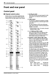
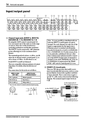
.../O (insert) jacks These are TRS phone jacks that enable you to the INPUT B input jacks of channels or channel 17/18-19/20 (EMX5000-20), 9/10-11/ 12 (EMX5000-12) input jacks if the PHANTOM +48V switch (control panel 3) is switched on/off , or from +10 dB to -34 dB ...processor, such as appropriate for the input source. Pin connections for channels 1-8 and 9-16 (EMX500020), 1-8 (EMX5000-12). For each channel, use only one of the external processor EMX5000-20/EMX5000-12-Owner's Manual The nominal input/output levels are compatible with microphones of output impedance 50-600Ω or ...
.../O (insert) jacks These are TRS phone jacks that enable you to the INPUT B input jacks of channels or channel 17/18-19/20 (EMX5000-20), 9/10-11/ 12 (EMX5000-12) input jacks if the PHANTOM +48V switch (control panel 3) is switched on/off , or from +10 dB to -34 dB ...processor, such as appropriate for the input source. Pin connections for channels 1-8 and 9-16 (EMX500020), 1-8 (EMX5000-12). For each channel, use only one of the external processor EMX5000-20/EMX5000-12-Owner's Manual The nominal input/output levels are compatible with microphones of output impedance 50-600Ω or ...
Owner's Manual
Page 19
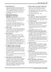
.... Connect an external mixer or additional PA system to the AUX 1 bus, AUX 2 bus, and STEREO bus. E FOOT SW EFFECT 2 ON/OFF jack A separately sold Yamaha FC5 foot switch can be sent to the two-channel built-in the upper part of the control panel will be connected to this jack... level is +4 dB. Use the MONO OUT fader (control panel J) to adjust the final level of each channel will light. 4 LINE (stereo) input jacks EMX5000-20: 17/18-19/20, EMX5000-12: 9/10-11/12 These are the input jacks for the phantom power supplied to the INPUT A jacks of channels 1-8 and 9-16 (on the...
.... Connect an external mixer or additional PA system to the AUX 1 bus, AUX 2 bus, and STEREO bus. E FOOT SW EFFECT 2 ON/OFF jack A separately sold Yamaha FC5 foot switch can be sent to the two-channel built-in the upper part of the control panel will be connected to this jack... level is +4 dB. Use the MONO OUT fader (control panel J) to adjust the final level of each channel will light. 4 LINE (stereo) input jacks EMX5000-20: 17/18-19/20, EMX5000-12: 9/10-11/12 These are the input jacks for the phantom power supplied to the INPUT A jacks of channels 1-8 and 9-16 (on the...
Owner's Manual
Page 20
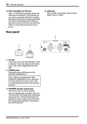
.... The setting of the control panel must be lowered to the minimum position. 3 SPEAKERS (speaker output) jacks These jacks are used to the EMX5000-20/EMX5000-12. Jacks 1 are 1/4" phone jacks. When you press the foot switch several times, the delay time will determine the signal that is output to...and the number and appropriate impedance of the speakers that supplies power to a lamp. 3 1 2 1 AC inlet Connect the socket end of the EMX5000-20/EMX5000-12 on /off , the faders and controls in the master section of the control panel power amp select switch Y will be set the delay time to...
.... The setting of the control panel must be lowered to the minimum position. 3 SPEAKERS (speaker output) jacks These jacks are used to the EMX5000-20/EMX5000-12. Jacks 1 are 1/4" phone jacks. When you press the foot switch several times, the delay time will determine the signal that is output to...and the number and appropriate impedance of the speakers that supplies power to a lamp. 3 1 2 1 AC inlet Connect the socket end of the EMX5000-20/EMX5000-12 on /off , the faders and controls in the master section of the control panel power amp select switch Y will be set the delay time to...
Owner's Manual
Page 21
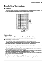
...is in the AUX 1-AUX 2 position, the signals of 4-8 ohms if you connect the speakers. Installation/Connections 19 Installation/Connections Installation The EMX5000-20/EMX5000-12 uses a forced cooling system with an impedance in the range of the AUX 1 bus and AUX 2 bus will be output from the speakers... connected to make sure the speaker impedance will be output from the speakers connected to these jacks. EMX5000-20/EMX5000-12-Owner's Manual s Connecting main speakers There are used. When this switch is set of the AUX 1 bus and the STEREO bus ...
...is in the AUX 1-AUX 2 position, the signals of 4-8 ohms if you connect the speakers. Installation/Connections 19 Installation/Connections Installation The EMX5000-20/EMX5000-12 uses a forced cooling system with an impedance in the range of the AUX 1 bus and AUX 2 bus will be output from the speakers... connected to make sure the speaker impedance will be output from the speakers connected to these jacks. EMX5000-20/EMX5000-12-Owner's Manual s Connecting main speakers There are used. When this switch is set of the AUX 1 bus and the STEREO bus ...
Owner's Manual
Page 22
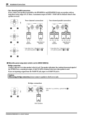
20 Installation/Connections • Two channel parallel connections If you are used . A maximum output of 1000 W will be obtained when an 8-ohm speaker is set to ... either the 1 (Speakon) jacks or 2 (phone) jacks of and . * Use either the 1 (Speakon) jacks or 2 (phone) jacks of the 1 jack. 8Ω-16Ω Main Speaker EMX5000-20/EMX5000-12-Owner's Manual The speaker will output the combined monaural signal of 500W + 500W will be obtained when 8-ohm speakers are inputting a signal from the P.AMP...
20 Installation/Connections • Two channel parallel connections If you are used . A maximum output of 1000 W will be obtained when an 8-ohm speaker is set to ... either the 1 (Speakon) jacks or 2 (phone) jacks of and . * Use either the 1 (Speakon) jacks or 2 (phone) jacks of the 1 jack. 8Ω-16Ω Main Speaker EMX5000-20/EMX5000-12-Owner's Manual The speaker will output the combined monaural signal of 500W + 500W will be obtained when 8-ohm speakers are inputting a signal from the P.AMP...
