

Owner's Manual
Page 1
...PROGRAMS 31 2-4.SELECTING SOUND FIELD PROGRAMS 31 2-5.MUTING THE EFFECT SOUND 32 2-6.SUPERIMPOSED VIDEO PROGRAM/PARAMETER DISPLAY 32 2-7.DESCRIPTIONS OF THE SOUND FIELD PROGRAMS 33 2-8.REMOTE CONTROL "LEARNING" FUNCTION 39 CREATING YOUR OWN SOUND FIELDS 41 3-1.SELECTING AND EDITING PROGRAM PARAMETERS 41 3-2.DESCRIPTIONS OF THE DIGITAL SOUND FIELD PARAMETERS 43 TABLES & SPECIFICATIONS 48 4-1.PROGRAM PARAMETER TABLE 48 4-2.TROUBLESHOOTING 51 4-3. DSP-A2070 DIGITAL SOUND FIELD PROCESSING AMPLIFIER OPERATION MANUAL CONTENTS SAFETY INSTRUCTIONS Inside Front cover SETUP & ADJUSTMENT...
...PROGRAMS 31 2-4.SELECTING SOUND FIELD PROGRAMS 31 2-5.MUTING THE EFFECT SOUND 32 2-6.SUPERIMPOSED VIDEO PROGRAM/PARAMETER DISPLAY 32 2-7.DESCRIPTIONS OF THE SOUND FIELD PROGRAMS 33 2-8.REMOTE CONTROL "LEARNING" FUNCTION 39 CREATING YOUR OWN SOUND FIELDS 41 3-1.SELECTING AND EDITING PROGRAM PARAMETERS 41 3-2.DESCRIPTIONS OF THE DIGITAL SOUND FIELD PARAMETERS 43 TABLES & SPECIFICATIONS 48 4-1.PROGRAM PARAMETER TABLE 48 4-2.TROUBLESHOOTING 51 4-3. DSP-A2070 DIGITAL SOUND FIELD PROCESSING AMPLIFIER OPERATION MANUAL CONTENTS SAFETY INSTRUCTIONS Inside Front cover SETUP & ADJUSTMENT...
Owner's Manual
Page 2
... Damage Requiring Service - The power-supply cord or the plug has been damaged; The user should be walked on or pinched by the manufacturer. 8 Ventilation - Precautions should be situated on the rear of the unit. Model: Serial No.: The serial number is operated. 2 Retain Instructions - SAFETY INSTRUCTIONS 1 Read Instructions - The unit should be taken so that they exit from heat sources such as...
... Damage Requiring Service - The power-supply cord or the plug has been damaged; The user should be walked on or pinched by the manufacturer. 8 Ventilation - Precautions should be situated on the rear of the unit. Model: Serial No.: The serial number is operated. 2 Retain Instructions - SAFETY INSTRUCTIONS 1 Read Instructions - The unit should be taken so that they exit from heat sources such as...
Owner's Manual
Page 3
... or fuse) circuits or install AC line filter/s. Then gently disconnect the power plug and the cords connecting to other electronic devices. Avoid sources of radio or TV interference, relocate/reorient the antenna. Compliance with these corrective measures do not expose to comply with chemical solvents; PRECAUTIONS 1 To ensure the finest performance, please read the "Troubleshooting" section on common operating errors before...
... or fuse) circuits or install AC line filter/s. Then gently disconnect the power plug and the cords connecting to other electronic devices. Avoid sources of radio or TV interference, relocate/reorient the antenna. Compliance with these corrective measures do not expose to comply with chemical solvents; PRECAUTIONS 1 To ensure the finest performance, please read the "Troubleshooting" section on common operating errors before...

Owner's Manual
Page 4
...-in channels of amplification on the DSP-A2070 mean that no additional amplifiers are the proud owner of listening experiences. The DSP system takes full advantage of Yamaha's undisputed leadership in the field of listening environments-anything from Dolby-encoded video tapes using the built-in a safe place for later reference. 2 Follow the instructions in this operation manual carefully and store it in Dolby Pro Logic Surround...
...-in channels of amplification on the DSP-A2070 mean that no additional amplifiers are the proud owner of listening experiences. The DSP system takes full advantage of Yamaha's undisputed leadership in the field of listening environments-anything from Dolby-encoded video tapes using the built-in a safe place for later reference. 2 Follow the instructions in this operation manual carefully and store it in Dolby Pro Logic Surround...
Owner's Manual
Page 8
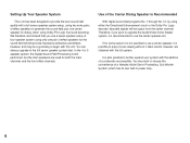
... built-in power amp. 6 Setting Up Your Speaker System This unit has been designed to provide the best sound field quality with a full seven-speaker system setup, using two extra pairs of effect speakers for the sound field will be a good way to begin with this unit. A four-speaker system using Dolby Pro Logic Surround decoding. We therefore recommend that you want to upgrade the Audio/Video home theater system, it...
... built-in power amp. 6 Setting Up Your Speaker System This unit has been designed to provide the best sound field quality with a full seven-speaker system setup, using two extra pairs of effect speakers for the sound field will be a good way to begin with this unit. A four-speaker system using Dolby Pro Logic Surround decoding. We therefore recommend that you want to upgrade the Audio/Video home theater system, it...
Owner's Manual
Page 13
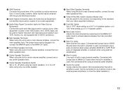
... inputs and/or outputs of your audio equipment. 3 Audio/Video Signal Connection Jacks (for higher resolution and improved picture quality if your VCR, monitor, etc. In some cases, however, better results may be connected to input jack(s) of the turntable to produce minimum hum. A Main Level Control Adjusts the main-channel line output level at the MAIN OUT jacks. 1 GND Terminal Connects the ground wire of one center speaker. 8 Rear Effect Speaker Terminals When using this switch...
... inputs and/or outputs of your audio equipment. 3 Audio/Video Signal Connection Jacks (for higher resolution and improved picture quality if your VCR, monitor, etc. In some cases, however, better results may be connected to input jack(s) of the turntable to produce minimum hum. A Main Level Control Adjusts the main-channel line output level at the MAIN OUT jacks. 1 GND Terminal Connects the ground wire of one center speaker. 8 Rear Effect Speaker Terminals When using this switch...
Owner's Manual
Page 14
... connected to input jacks of the correct setting. "Switched" means that power is connected to the line voltage in your dealer if unsure of an external stereo power amplifier driving the front effect speakers. F Mono Low Pass Jack When using an external power amplifier. Frequencies below 200 Hz from the left main and center channels are output (in center-channel amplifier. Can be available at the speaker terminals. 12 K Switched AC Outlets You may plug other audio components...
... connected to input jacks of the correct setting. "Switched" means that power is connected to the line voltage in your dealer if unsure of an external stereo power amplifier driving the front effect speakers. F Mono Low Pass Jack When using an external power amplifier. Frequencies below 200 Hz from the left main and center channels are output (in center-channel amplifier. Can be available at the speaker terminals. 12 K Switched AC Outlets You may plug other audio components...

Owner's Manual
Page 17
... unit, signals of screen display information are output from either S VIDEO or VIDEO input jacks of your monitor. Video disc player VIDEO OUT S-VIDEO OUT NOTE: If your unit is the General Model, be output from both S VIDEO MONITOR OUT and VIDEO MONITOR OUT jacks with "S" (high-resolution) video terminals, connect them to this unit's S VIDEO jacks, and connect this unit's S VIDEO MONITOR OUT jack to both S VIDEO input and VIDEO input jacks, the signals will be sure the VIDEO NTSC/PAL switch has been correctly set to...
... unit, signals of screen display information are output from either S VIDEO or VIDEO input jacks of your monitor. Video disc player VIDEO OUT S-VIDEO OUT NOTE: If your unit is the General Model, be output from both S VIDEO MONITOR OUT and VIDEO MONITOR OUT jacks with "S" (high-resolution) video terminals, connect them to this unit's S VIDEO jacks, and connect this unit's S VIDEO MONITOR OUT jack to both S VIDEO input and VIDEO input jacks, the signals will be sure the VIDEO NTSC/PAL switch has been correctly set to...
Owner's Manual
Page 20
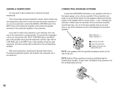
... the knob and secure the wire. This unit provides line-level subwoofer outputs, which contain only the frequencies under 200 Hz from the speakers. With some subwoofers, including the Yamaha Active Servo Processing Subwoofer System, the amplifier and subwoofer are reversed, the sound will lack bass. Do not let the bare speaker wires touch each subwoofer to the INPUT jack of the subwoofer amplifier, and connect the speaker terminals of the proper...
... the knob and secure the wire. This unit provides line-level subwoofer outputs, which contain only the frequencies under 200 Hz from the speakers. With some subwoofers, including the Yamaha Active Servo Processing Subwoofer System, the amplifier and subwoofer are reversed, the sound will lack bass. Do not let the bare speaker wires touch each subwoofer to the INPUT jack of the subwoofer amplifier, and connect the speaker terminals of the proper...
Owner's Manual
Page 21
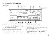
... mode, the indicator is half illuminated.) 2 Remote control sensor Signals from the remote control unit are received here. 3 Pro Logic Decoder Indicator Illuminates while the built-in Dolby Pro Logic Surround Decoder is being activated. 4 Sound Field Processor Indicator Illuminates while the built-in Sound Field Processor is being activated. 5 Display Panel Shows program names, parameters and information about other various settings and adjustments. 6 Tape 2 Monitor Switch Used when you have connected a second tape deck...
... mode, the indicator is half illuminated.) 2 Remote control sensor Signals from the remote control unit are received here. 3 Pro Logic Decoder Indicator Illuminates while the built-in Dolby Pro Logic Surround Decoder is being activated. 4 Sound Field Processor Indicator Illuminates while the built-in Sound Field Processor is being activated. 5 Display Panel Shows program names, parameters and information about other various settings and adjustments. 6 Tape 2 Monitor Switch Used when you have connected a second tape deck...

Owner's Manual
Page 22
... main channels. If the connected video equipment has a S video output terminal, connect it to the S VIDEO jack to (and watch). 8 Master Volume Control Simultaneously controls signal level at the main left and right output volume to the Main Speakers to match your tastes. 7 Input Selector Selects the input source that you do not have a subwoofer, the use of this switch will be recorded to these jacks. If the FRONT MIX and EFFECT switches are CENTER MODE, CENTER GEQ, LOW FREQ...
... main channels. If the connected video equipment has a S video output terminal, connect it to the S VIDEO jack to (and watch). 8 Master Volume Control Simultaneously controls signal level at the main left and right output volume to the Main Speakers to match your tastes. 7 Input Selector Selects the input source that you do not have a subwoofer, the use of this switch will be recorded to these jacks. If the FRONT MIX and EFFECT switches are CENTER MODE, CENTER GEQ, LOW FREQ...
Owner's Manual
Page 23
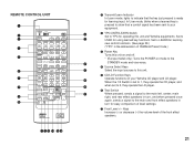
M 2 YPC/USER/LEARN Switch Set to YPC for learning new control functions. (See page 39.) ("YPC" is the abbreviation of YAMAHA Preset Code.) 3 Power Key Turns this unit on and off. * (Europe model only): Turns the POWER on mode to the K STANDBY mode and vice versa. 4 Source Select Keys J Select the input sources to your Yamaha CD player and LD player. Keys Increase (+) or decrease (-) the volume level of level settings. 7 Front Level +/- In User mode, blinks when a learned key is pressed to...
M 2 YPC/USER/LEARN Switch Set to YPC for learning new control functions. (See page 39.) ("YPC" is the abbreviation of YAMAHA Preset Code.) 3 Power Key Turns this unit on and off. * (Europe model only): Turns the POWER on mode to the K STANDBY mode and vice versa. 4 Source Select Keys J Select the input sources to your Yamaha CD player and LD player. Keys Increase (+) or decrease (-) the volume level of level settings. 7 Front Level +/- In User mode, blinks when a learned key is pressed to...

Owner's Manual
Page 24
...) Select programs 1 through 12. J Tuner Function Keys Operate Yamaha tuner functions. L Blank Keys Have no display in USER or LEARN mode to keys for use with either the CD player or LD player. ("1" for the CD player and "2" for seven types of the rear effect speakers. : Reset Button Press this switch selects page 1 or 2 for learning other remote controller's functions only. While muting, the indicator on the master VOLUME control flashes on the connected monitor's screen. A On Screen Display Key Changes the type of settings/adjustments...
...) Select programs 1 through 12. J Tuner Function Keys Operate Yamaha tuner functions. L Blank Keys Have no display in USER or LEARN mode to keys for use with either the CD player or LD player. ("1" for the CD player and "2" for seven types of the rear effect speakers. : Reset Button Press this switch selects page 1 or 2 for learning other remote controller's functions only. While muting, the indicator on the master VOLUME control flashes on the connected monitor's screen. A On Screen Display Key Changes the type of settings/adjustments...
Owner's Manual
Page 25
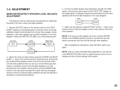
... effect speaker level adjustment, depress the TEST switch on the rear panel and adjust the center and rear level again. You will then hear the center channel test tone from the main speakers when you may also be at a normal listening position. Adjust the MASTER VOLUME to be adjusted if necessary to enter test mode. Left main LEFT Center CENTER Rear SURROUND Right main RIGHT 2. NOTE: If not using the CENTER and REAR LEVEL +/- keys on the remote control so that the sound...
... effect speaker level adjustment, depress the TEST switch on the rear panel and adjust the center and rear level again. You will then hear the center channel test tone from the main speakers when you may also be at a normal listening position. Adjust the MASTER VOLUME to be adjusted if necessary to enter test mode. Left main LEFT Center CENTER Rear SURROUND Right main RIGHT 2. NOTE: If not using the CENTER and REAR LEVEL +/- keys on the remote control so that the sound...

Owner's Manual
Page 27
...changed by using the INPUT TRIM control and the SET MENU switch on the monitor screen). 1. LOW FREQ. PARAMETER INIT 5. Set the PARAMETER/SET MENU switch to use this operation. 25 VCR3 VIDEO OUT 7. OTHER IMPORTANT SETTINGS AND ADJUSTMENTS The following seven types of setting/adjustment. Note that these settings and adjustments watching the information displayed on the remote control unit. CENTER GEQ 3. CENTER LEVEL TV THEATER 9 MOVIE THEATER 1 10 MOVIE THEATER 2 11 PRO LOGIC 12 ON SCREEN PARAMETER REAR LEVEL EFFECT ON/OFF SET MENU MASTER VOLUME MUTING RESET...
...changed by using the INPUT TRIM control and the SET MENU switch on the monitor screen). 1. LOW FREQ. PARAMETER INIT 5. Set the PARAMETER/SET MENU switch to use this operation. 25 VCR3 VIDEO OUT 7. OTHER IMPORTANT SETTINGS AND ADJUSTMENTS The following seven types of setting/adjustment. Note that these settings and adjustments watching the information displayed on the remote control unit. CENTER GEQ 3. CENTER LEVEL TV THEATER 9 MOVIE THEATER 1 10 MOVIE THEATER 2 11 PRO LOGIC 12 ON SCREEN PARAMETER REAR LEVEL EFFECT ON/OFF SET MENU MASTER VOLUME MUTING RESET...

Owner's Manual
Page 29
TEST) The internal low frequency test-tone generator is useful for adjustment. 2. Hiss-like calibration signal is output instead of this unit and the speaker(s) corresponding to "TEST TONE- - - key, select a channel (MAIN/CENTER/REAR EFFECT/FRONT EFFECT) to be compared with the control on the subwoofer so that the test tone can be changed from the subwoofer(s) connected to 250 Hz in your room. OFF". Next press the Parameter + or - NOTE: This low frequency test-tone can...
TEST) The internal low frequency test-tone generator is useful for adjustment. 2. Hiss-like calibration signal is output instead of this unit and the speaker(s) corresponding to "TEST TONE- - - key, select a channel (MAIN/CENTER/REAR EFFECT/FRONT EFFECT) to be compared with the control on the subwoofer so that the test tone can be changed from the subwoofer(s) connected to 250 Hz in your room. OFF". Next press the Parameter + or - NOTE: This low frequency test-tone can...
Owner's Manual
Page 30
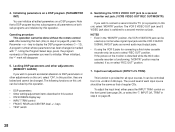
...; TEST switch 6. Locking DSP parameters and other adjustments on the front panel (see page 24), or select the "7. Input level adjustment (INPUT LVL TRIM) This function is provided for connecting a third video cassette recorder only, be the same as normal audio input/output jacks. • If using the VCR 3 jacks for all edited parameters on the monitor is disturbed while the third video cassette recorder is switched to display the DSP program numbers (1 - 12). To adjust the input level...
...; TEST switch 6. Locking DSP parameters and other adjustments on the front panel (see page 24), or select the "7. Input level adjustment (INPUT LVL TRIM) This function is provided for connecting a third video cassette recorder only, be the same as normal audio input/output jacks. • If using the VCR 3 jacks for all edited parameters on the monitor is disturbed while the third video cassette recorder is switched to display the DSP program numbers (1 - 12). To adjust the input level...
Owner's Manual
Page 31
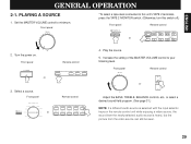
... Set the MASTER VOLUME control to your listening level. Front panel POWER or Remote control POWER TV VCR 1 VCR 2 3. PLAYING A SOURCE 1. Front panel Remote control INPUT SELECTOR LD TV/DBS TAPE 1 VCR 1 TAPE 2 MONITOR VCR 2 TUNER CD VCR 3 AUX PHONO or AUX PHONO TAPE 1 TUNER CD VCR 3 VCR 2 VCR 1 TV/DBS LD 4. Increase the setting of the MASTER VOLUME control to minimum. Front panel *To select a tape deck connected to this unit's TAPE 2 terminals, press the TAPE 2 MONITOR switch. (Otherwise, turn this switch off.) Front panel TAPE 2 MONITOR or Remote control TAPE...
... Set the MASTER VOLUME control to your listening level. Front panel POWER or Remote control POWER TV VCR 1 VCR 2 3. PLAYING A SOURCE 1. Front panel Remote control INPUT SELECTOR LD TV/DBS TAPE 1 VCR 1 TAPE 2 MONITOR VCR 2 TUNER CD VCR 3 AUX PHONO or AUX PHONO TAPE 1 TUNER CD VCR 3 VCR 2 VCR 1 TV/DBS LD 4. Increase the setting of the MASTER VOLUME control to minimum. Front panel *To select a tape deck connected to this unit's TAPE 2 terminals, press the TAPE 2 MONITOR switch. (Otherwise, turn this switch off.) Front panel TAPE 2 MONITOR or Remote control TAPE...
Owner's Manual
Page 41
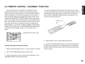
... switch to User mode. REMOTE CONTROL "LEARNING" FUNCTION The remote control unit, in your system or other remote control unit. Also, each capable of the main unit and other remote control unit corresponding to the new function to be used to record the functions learned by the various keys. 39 CENTER LEVEL TV THEATER 9 MOVIE THEATER 1 10 MOVIE THEATER 2 11 PRO LOGIC 12 ON SCREEN PARAMETER REAR LEVEL EFFECT ON/OFF SET MENU MASTER VOLUME MUTING RESET CLEAR PARAMETER/SET MENU switch...
... switch to User mode. REMOTE CONTROL "LEARNING" FUNCTION The remote control unit, in your system or other remote control unit. Also, each capable of the main unit and other remote control unit corresponding to the new function to be used to record the functions learned by the various keys. 39 CENTER LEVEL TV THEATER 9 MOVIE THEATER 1 10 MOVIE THEATER 2 11 PRO LOGIC 12 ON SCREEN PARAMETER REAR LEVEL EFFECT ON/OFF SET MENU MASTER VOLUME MUTING RESET CLEAR PARAMETER/SET MENU switch...
Owner's Manual
Page 53
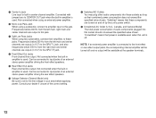
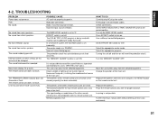
.... No front reflection sound. The sound field cannot be changed. The remote control unit does not work . POSSIBLE CAUSE AC cord not properly plugged in all connection cables. The DOLBY PRO LOGIC program is in "PHNTM". The center mode is being used with material not encoded with this unit cannot be recorded. WHAT TO DO Carefully plug AC plug into outlet. Turn up the MAIN LEVEL control. Direct sunlight or lighting (of an...
.... No front reflection sound. The sound field cannot be changed. The remote control unit does not work . POSSIBLE CAUSE AC cord not properly plugged in all connection cables. The DOLBY PRO LOGIC program is in "PHNTM". The center mode is being used with material not encoded with this unit cannot be recorded. WHAT TO DO Carefully plug AC plug into outlet. Turn up the MAIN LEVEL control. Direct sunlight or lighting (of an...


