
D1500 Owners Manual Image
Page 1
The O15W has the distinction of pro- Contents Front Panel Controls 1 Rear Panel Operation 3 Sample Settings Application Examples 5 Specifications 6 Block Diagram 7 YAMAHA D1500 DIGITAL DELAY OPERATING MANUAL Introduction The Yamaha O1500 is a high-performance digital delay system that is capable of being the world's first MIDI(MusicalInstrument Digital Interface) compatible delay system. The O1500 uses state-of-the-art digital technology to obtain the best possible performance from a MIDI keyboard or other MIDI equipment, vastly broadening its...
The O15W has the distinction of pro- Contents Front Panel Controls 1 Rear Panel Operation 3 Sample Settings Application Examples 5 Specifications 6 Block Diagram 7 YAMAHA D1500 DIGITAL DELAY OPERATING MANUAL Introduction The Yamaha O1500 is a high-performance digital delay system that is capable of being the world's first MIDI(MusicalInstrument Digital Interface) compatible delay system. The O1500 uses state-of-the-art digital technology to obtain the best possible performance from a MIDI keyboard or other MIDI equipment, vastly broadening its...
D1500 Owners Manual Image
Page 2
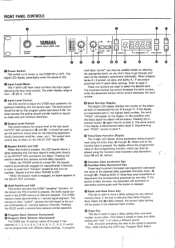
... the function keys is then "cycled", causing the held and repeated. Pressing either Program Bank Select Key 0 or Ois pressed, the current delay setting will be stored in hexidecimal format (0 through e). F are used to set so that the input signal is used to copy a delay setting from -20 dB to bank 0. The output level control has no data, and banks A- FRONT PANEL CONTROLS w .O'✓ tor, POWER YAMAHA DIGITAL DELAY MODEL D1500 ♦6 H.-20 10 LE L INPUT E . The digital LED display panel lights...
... the function keys is then "cycled", causing the held and repeated. Pressing either Program Bank Select Key 0 or Ois pressed, the current delay setting will be stored in hexidecimal format (0 through e). F are used to set so that the input signal is used to copy a delay setting from -20 dB to bank 0. The output level control has no data, and banks A- FRONT PANEL CONTROLS w .O'✓ tor, POWER YAMAHA DIGITAL DELAY MODEL D1500 ♦6 H.-20 10 LE L INPUT E . The digital LED display panel lights...
D1500 Owners Manual Image
Page 3
... (Low Frequency Oscillator) waveforms to create different modulation effects. Pressing this key causes its LED to light, and the delay time programmed in the D1500 basically determines the number of the "mix" (balance) • between the direct and delay sound. The data range is received. level) with a setting of phase with the direct signal. Pressing the MIDI CH key a second time stores the data and disengages the MIDI channel selection mode. ' The D1500 can be adjusted using the Function Data Increment...
... (Low Frequency Oscillator) waveforms to create different modulation effects. Pressing this key causes its LED to light, and the delay time programmed in the D1500 basically determines the number of the "mix" (balance) • between the direct and delay sound. The data range is received. level) with a setting of phase with the direct signal. Pressing the MIDI CH key a second time stores the data and disengages the MIDI channel selection mode. ' The D1500 can be adjusted using the Function Data Increment...
D1500 Owners Manual Image
Page 4
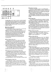
... diagram Cold s T / Ground Hot LO-Z 3 1 2 S T HI-Z (I ,... r et_, ()YAMAHA vt.TACIE SELCCTO. Pressing the MIDI PGM key a second time stores the data and disengages the MIDI Program Change function. A standard MIDI connection cable is used where a specific waveform is turned OFF, the front-panel LFO Rate LED will by selected by means other MIDI equip- Mixed Output Jack (Balanced TRS Phone) ED Mixed Output Jack (Balanced XLR) The mixed (direct and delay signal, mix ratio set to mix the direct and delayed sound at the MIDI...
... diagram Cold s T / Ground Hot LO-Z 3 1 2 S T HI-Z (I ,... r et_, ()YAMAHA vt.TACIE SELCCTO. Pressing the MIDI PGM key a second time stores the data and disengages the MIDI Program Change function. A standard MIDI connection cable is used where a specific waveform is turned OFF, the front-panel LFO Rate LED will by selected by means other MIDI equip- Mixed Output Jack (Balanced TRS Phone) ED Mixed Output Jack (Balanced XLR) The mixed (direct and delay signal, mix ratio set to mix the direct and delayed sound at the MIDI...
D1500 Owners Manual Image
Page 5
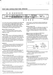
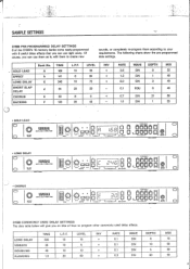
... MIX 10. 50 50 50 4 TIME L.P.F. I 1 ::), I O. ,_- O SO D. TA.YS• fog -- ''''' .."' © BANK SALMI 0 D1500 COMMONLY USED DELAY SETTINGS The data table below will give you can use them according to create new sounds, or completely re-program them as is • • •••• 0..MV I ,- Of course, you an idea of the D1500's 16 memory banks come ready-programmed with 6 useful delay effects...
... MIX 10. 50 50 50 4 TIME L.P.F. I 1 ::), I O. ,_- O SO D. TA.YS• fog -- ''''' .."' © BANK SALMI 0 D1500 COMMONLY USED DELAY SETTINGS The data table below will give you can use them according to create new sounds, or completely re-program them as is • • •••• 0..MV I ,- Of course, you an idea of the D1500's 16 memory banks come ready-programmed with 6 useful delay effects...
D1500 Owners Manual Image
Page 6
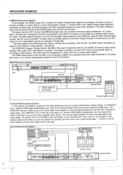
... jack input via a standard MIDI connection cable. The MIDI interface is then fed either a music in combination with reverb added. The data which do not require delay effects. The D1500 MIDI Program Change function (see 24) must be selected when a given DX7 voice selector is used to a sound reinforcement console via the XLR connector. The MIDI transmit channel of the DX7 and the MIDI receive channel of a sound reinforcement mixing console, in - With the DX1, the MIDI Program Numbers...
... jack input via a standard MIDI connection cable. The MIDI interface is then fed either a music in combination with reverb added. The data which do not require delay effects. The D1500 MIDI Program Change function (see 24) must be selected when a given DX7 voice selector is used to a sound reinforcement console via the XLR connector. The MIDI transmit channel of the DX7 and the MIDI receive channel of a sound reinforcement mixing console, in - With the DX1, the MIDI Program Numbers...
D1500 Owners Manual Image
Page 7
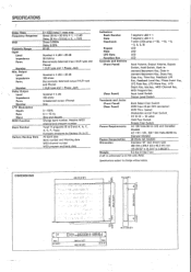
.../decrement Key, Data in - SPECIFICATIONS Delay Time 0-1023 msec/1 msec step Frequency Response Direct 20 Hz-20 KHz + 1, -2 dB Delay 20 Hz -18 KHz + 3, - 3dB THD . crement/decrement Key, Store Key, Copy Key, Time Key, Feedback LPF Key, Feedback Level Key, Phase Invert Key, LFO Rate Key, LFO Wave Key, LFO Depth Key, Mix Key, MIDI Channel Key, MIDI Program Key (Rear Panel) Input Level Switch Output Level Switch Terminals and Jacks (Front Panel) Bank Select Foot Switch (Rear Panel) MIDI Input (5 pin DIN connector) MIDI Thru. (same) Modulation on/off Foot Switch. DIMENSIONS...
.../decrement Key, Data in - SPECIFICATIONS Delay Time 0-1023 msec/1 msec step Frequency Response Direct 20 Hz-20 KHz + 1, -2 dB Delay 20 Hz -18 KHz + 3, - 3dB THD . crement/decrement Key, Store Key, Copy Key, Time Key, Feedback LPF Key, Feedback Level Key, Phase Invert Key, LFO Rate Key, LFO Wave Key, LFO Depth Key, Mix Key, MIDI Channel Key, MIDI Program Key (Rear Panel) Input Level Switch Output Level Switch Terminals and Jacks (Front Panel) Bank Select Foot Switch (Rear Panel) MIDI Input (5 pin DIN connector) MIDI Thru. (same) Modulation on/off Foot Switch. DIMENSIONS...
D1500 Owners Manual Image
Page 8
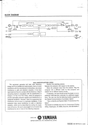
... receiver. Plug the interference to radio or television blems". L•P•F 1-f FO LEVEL FDL-P•F ,~ MIXING f Li_ f OE AY BA OUTPUT LEVEL •4 -20 LEVEL SW 0A MIX OUT owl O DELAY O_ OUT IN MIDI THRU FCC CERTIFICATION (USA) This equipment generates and uses radio frequency Reorient the receiving antenna. Subpart J of Part 15 of the following booklet prepared by turning the...
... receiver. Plug the interference to radio or television blems". L•P•F 1-f FO LEVEL FDL-P•F ,~ MIXING f Li_ f OE AY BA OUTPUT LEVEL •4 -20 LEVEL SW 0A MIX OUT owl O DELAY O_ OUT IN MIDI THRU FCC CERTIFICATION (USA) This equipment generates and uses radio frequency Reorient the receiving antenna. Subpart J of Part 15 of the following booklet prepared by turning the...


