
D1030 Owners Manual Image
Page 3
... crossover plus sub-woofer with delay for each output. 15 memory locations are provided so preset programs including delay and EQ settings can be recalled via the front-panel controls, by using a contact-closure system, or via MIDI. The D1030 offers sound quality, programmability and...mode change lockout for system protection. • MIDI interface for each output. • Delay time may be prepared and easily recalled when needed. Introduction The D1030 Digital Delay Line is a high-performance delay line with onboard EQ designed for a broad range of up to 1300 milliseconds (20-...
... crossover plus sub-woofer with delay for each output. 15 memory locations are provided so preset programs including delay and EQ settings can be recalled via the front-panel controls, by using a contact-closure system, or via MIDI. The D1030 offers sound quality, programmability and...mode change lockout for system protection. • MIDI interface for each output. • Delay time may be prepared and easily recalled when needed. Introduction The D1030 Digital Delay Line is a high-performance delay line with onboard EQ designed for a broad range of up to 1300 milliseconds (20-...

D1030 Owners Manual Image
Page 4
... PARAMETERS & PROCEDURE EQ & SUBSONIC FILTER SWITCHING DELAY & CROSSOVER MODE PROGRAMS AND PROGRAM SELECTION THE COMPARE FUNCTION ■ A/B/C: 3-CHANNEL DELAY + 3-WAY CROSSOVER FUNCTIONAL BLOCK DIAGRAM BASIC SYSTEM CONFIGURATION 3-WAY CROSSOVER PARAMETERS & PROCEDURE ■ D/E/F: DELAY + 2-WAY CROSSOVER + SUB-WOOFER FUNCTIONAL BLOCK... PROGRAM STORE REALTIME MIDI PARAMETER CONTROL HARD-WIRED PROGRAM SELECTION MIDI LINK UTILITY MODE FUNCTIONS TITLE EDIT DELAY DISPLAY LEVEL METER MIDI CONTROL MIDI PROGRAM CHANGE TABLE CONTROLLER ASSIGNMENT BULK OUT TIME ALIGNMENT BASICS DISTANCE COMPENSATION...
... PARAMETERS & PROCEDURE EQ & SUBSONIC FILTER SWITCHING DELAY & CROSSOVER MODE PROGRAMS AND PROGRAM SELECTION THE COMPARE FUNCTION ■ A/B/C: 3-CHANNEL DELAY + 3-WAY CROSSOVER FUNCTIONAL BLOCK DIAGRAM BASIC SYSTEM CONFIGURATION 3-WAY CROSSOVER PARAMETERS & PROCEDURE ■ D/E/F: DELAY + 2-WAY CROSSOVER + SUB-WOOFER FUNCTIONAL BLOCK... PROGRAM STORE REALTIME MIDI PARAMETER CONTROL HARD-WIRED PROGRAM SELECTION MIDI LINK UTILITY MODE FUNCTIONS TITLE EDIT DELAY DISPLAY LEVEL METER MIDI CONTROL MIDI PROGRAM CHANGE TABLE CONTROLLER ASSIGNMENT BULK OUT TIME ALIGNMENT BASICS DISTANCE COMPENSATION...
D1030 Owners Manual Image
Page 6
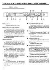
... the level indicator take-off in the "DELAY & PARAMETRIC EQ (P.EQ)" or "DELAY & CROSSOVER (X-OVER)" mode, selected by the (e rear-panel MODE switch MODE switch, below). • MEMORY Display This 7-segment LED display shows which of the D1030's three outputs. See page 17 for further... power ON or OFF. • Input & Output Level Indicators These 8-element LED level meters provide ac- O Mode Indicators Indicate whether the D1030 is in the DELAY & PARAMETRIC EQUALIZER mode. The display is backlit for easy operation and programming. E) • Power Switch Press to -42, -36, -...
... the level indicator take-off in the "DELAY & PARAMETRIC EQ (P.EQ)" or "DELAY & CROSSOVER (X-OVER)" mode, selected by the (e rear-panel MODE switch MODE switch, below). • MEMORY Display This 7-segment LED display shows which of the D1030's three outputs. See page 17 for further... power ON or OFF. • Input & Output Level Indicators These 8-element LED level meters provide ac- O Mode Indicators Indicate whether the D1030 is in the DELAY & PARAMETRIC EQUALIZER mode. The display is backlit for easy operation and programming. E) • Power Switch Press to -42, -36, -...
D1030 Owners Manual Image
Page 7
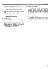
...to set up the optimum input level for further details. ® DELAY BYPASS Key One-touch delay bypass. el UTILITY Key The UTILITY key accesses a range of the D1030 input to the source signal. Use in any of the D1030 memory locations. See pages 8, 11 and 13 for further details. When... this key is selected (memory locations A through F). Pressing the key a second time causes its indicator will light and all delays are unaffected. le INPUT Level Control Matches the...
...to set up the optimum input level for further details. ® DELAY BYPASS Key One-touch delay bypass. el UTILITY Key The UTILITY key accesses a range of the D1030 input to the source signal. Use in any of the D1030 memory locations. See pages 8, 11 and 13 for further details. When... this key is selected (memory locations A through F). Pressing the key a second time causes its indicator will light and all delays are unaffected. le INPUT Level Control Matches the...
D1030 Owners Manual Image
Page 8
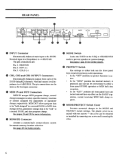
... specific memory locations or control assigned EQ parameters or parameter change, respectively. MODE/PROTECT Switch Cover Prevents unwanted changes to the D1030. MIDI OUT allows program data to be "bulk dumped" to be removed or installed by either lock out the front panel... (15 CH1, CH2 and CH3 OUTPUT Connectors Electronically balanced outputs from each of the D1030 delay/EQ channels. the cover can not be overwritten by removing one screw and loosening the other. 6 PM15 FOOLS ()YAMAHA Doff MAMIE ,•C) MOE JUANA • INPUT Connector Electronically balanced main input to...
... specific memory locations or control assigned EQ parameters or parameter change, respectively. MODE/PROTECT Switch Cover Prevents unwanted changes to the D1030. MIDI OUT allows program data to be "bulk dumped" to be removed or installed by either lock out the front panel... (15 CH1, CH2 and CH3 OUTPUT Connectors Electronically balanced outputs from each of the D1030 delay/EQ channels. the cover can not be overwritten by removing one screw and loosening the other. 6 PM15 FOOLS ()YAMAHA Doff MAMIE ,•C) MOE JUANA • INPUT Connector Electronically balanced main input to...

D1030 Owners Manual Image
Page 9
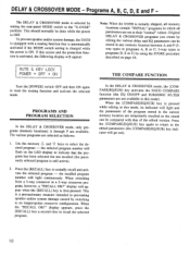
...To prevent speaker and/or system damage, the D1030 is equipped with a muting function that the program has been selected but not recalled (the previously selected program is still active. 2. PROGRAMS AND PROGRAM SELECTION In the DELAY & PARAMETRIC EQUALIZER mode, only programs (memory... programs are available. Note: When the D1030 is activated, the following display will light continuously. P0IEF cV".' EC) SUBSONIC P EC/ D/A LPF D/A LPF D/A LPF 0.0 +4dBm CH1 00° +4dBm CH2 0.0 +4dBm CH3 7 Memory Locations 1... 9 - The DELAY & PARAMETRIC EQUALIZER mode is selected by ...
...To prevent speaker and/or system damage, the D1030 is equipped with a muting function that the program has been selected but not recalled (the previously selected program is still active. 2. PROGRAMS AND PROGRAM SELECTION In the DELAY & PARAMETRIC EQUALIZER mode, only programs (memory... programs are available. Note: When the D1030 is activated, the following display will light continuously. P0IEF cV".' EC) SUBSONIC P EC/ D/A LPF D/A LPF D/A LPF 0.0 +4dBm CH1 00° +4dBm CH2 0.0 +4dBm CH3 7 Memory Locations 1... 9 - The DELAY & PARAMETRIC EQUALIZER mode is selected by ...

D1030 Owners Manual Image
Page 11
...channel. ON El ON E ON 'Ile. El indicates the channel-2 (CH2) parameter. indicates the channel-3 (CH3) parameter. DELAY, ATTENUATION & PHASE PARAMETERS & PROCEDURE These parameters operate the same in all D1030 modes. See page 17 for each channel, and the "SUB." allows switching the internal subsonic filter (20 Hz, -12 ... using the < and > CURSOR keys, then switch ON or OFF using the parameter editing Q and keys. 9 EQ & SUBSONIC FILTER SWITCHING In the DELAY & PARAMETRIC EQUALIZER mode, the [EQ/SUB] key alternately selects the following two display screens: EQ,SUB COMPARE P 'EC!
...channel. ON El ON E ON 'Ile. El indicates the channel-2 (CH2) parameter. indicates the channel-3 (CH3) parameter. DELAY, ATTENUATION & PHASE PARAMETERS & PROCEDURE These parameters operate the same in all D1030 modes. See page 17 for each channel, and the "SUB." allows switching the internal subsonic filter (20 Hz, -12 ... using the < and > CURSOR keys, then switch ON or OFF using the parameter editing Q and keys. 9 EQ & SUBSONIC FILTER SWITCHING In the DELAY & PARAMETRIC EQUALIZER mode, the [EQ/SUB] key alternately selects the following two display screens: EQ,SUB COMPARE P 'EC!
D1030 Owners Manual Image
Page 12
... has been selected but not recalled (the previously selected program is ON. THE COMPARE FUNCTION In the DELAY & CROSSOVER mode, the [COMPARE/EQ/SUB] key activates the D1030 COMPARE function (the EQ ON/OFF and SUBSONIC FILTER parameters are not available in the current memory location... protection function is activated, the f011owing display will appear: Note: When the D1030 is initially shipped, all parameters are temporarily recalled so the sound can be done while the power is OFF. The DELAY & CROSSOVER mode is a precautionary measure intended to preventing speaker and/or system...
... has been selected but not recalled (the previously selected program is ON. THE COMPARE FUNCTION In the DELAY & CROSSOVER mode, the [COMPARE/EQ/SUB] key activates the D1030 COMPARE function (the EQ ON/OFF and SUBSONIC FILTER parameters are not available in the current memory location... protection function is activated, the f011owing display will appear: Note: When the D1030 is initially shipped, all parameters are temporarily recalled so the sound can be done while the power is OFF. The DELAY & CROSSOVER mode is a precautionary measure intended to preventing speaker and/or system...

D1030 Owners Manual Image
Page 13
■ A/B/C: 3-CHANNEL DELAY + 3-WAY CROSSOVER • FUNCTIONAL BLOCK DIAGRAM 3WAY ri INPUT +4dBm 0.0 HA PRE-EM A/D 1=1 1=1 DELAY 0 LOW I-PF LO ATT r- D/A LPF MID-LO MID-HI DELAY ATT r D/A LPF DELAY ATT HIGH HIGI LPF r D/A LPF +4dBm LOW (CHi) +4dBm MID (CH2) +4dBm HIGH (CH3) • BASIC SYSTEM CONFIGULATION CH3 (HIGH) POWER AMPLIFIERS HF HORN • CH2 (LOW) MIDRANGE CH1 (LOW) INPUT D1030 LF HORN DELAY, ATTENUATION & PHASE PARAMETERS & PROCEDURE These parameters operate the same in all D1030 modes. See page 17 for details. 11
■ A/B/C: 3-CHANNEL DELAY + 3-WAY CROSSOVER • FUNCTIONAL BLOCK DIAGRAM 3WAY ri INPUT +4dBm 0.0 HA PRE-EM A/D 1=1 1=1 DELAY 0 LOW I-PF LO ATT r- D/A LPF MID-LO MID-HI DELAY ATT r D/A LPF DELAY ATT HIGH HIGI LPF r D/A LPF +4dBm LOW (CHi) +4dBm MID (CH2) +4dBm HIGH (CH3) • BASIC SYSTEM CONFIGULATION CH3 (HIGH) POWER AMPLIFIERS HF HORN • CH2 (LOW) MIDRANGE CH1 (LOW) INPUT D1030 LF HORN DELAY, ATTENUATION & PHASE PARAMETERS & PROCEDURE These parameters operate the same in all D1030 modes. See page 17 for details. 11
D1030 Owners Manual Image
Page 16
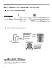
... + SUB-WOOFER • FUNCTIONAL BLOCK DIAGRAM r 2WAY + SUB-IN ri L INPUT +4dBm 0.0 HA PRE-EM A/D DELAY 0 DELAY 0 DELAY 0 SUB- TET a a D/A LOW HPF LO ATT D/A HIGH HIGH LPF ATT r D/A Z -EN LPF DE-EN LPF LPF 01. I-PF SUB-W ATT I- DELAY, ATTENUATION & PHASE PARAMETERS & PROCEDURE These parameters operate the same in place of a subwoofer if the... SUB-W (CH1) +4dBm LOW (CH2) +4dBm HIGH (CH3) • BASIC SYSTEM CONFIGULATION INPUT CH3 (HIGH) POWER AMPLIFIERS CH2 (LOW) CH1 (SUB-W) HF HORN LF HORN D1030 SUB-WOOFER A full-range auxilliary speaker can be used in all...
... + SUB-WOOFER • FUNCTIONAL BLOCK DIAGRAM r 2WAY + SUB-IN ri L INPUT +4dBm 0.0 HA PRE-EM A/D DELAY 0 DELAY 0 DELAY 0 SUB- TET a a D/A LOW HPF LO ATT D/A HIGH HIGH LPF ATT r D/A Z -EN LPF DE-EN LPF LPF 01. I-PF SUB-W ATT I- DELAY, ATTENUATION & PHASE PARAMETERS & PROCEDURE These parameters operate the same in place of a subwoofer if the... SUB-W (CH1) +4dBm LOW (CH2) +4dBm HIGH (CH3) • BASIC SYSTEM CONFIGULATION INPUT CH3 (HIGH) POWER AMPLIFIERS CH2 (LOW) CH1 (SUB-W) HF HORN LF HORN D1030 SUB-WOOFER A full-range auxilliary speaker can be used in all...
D1030 Owners Manual Image
Page 19
... The attenuator block for all three channels. Use the Q and 7 parameter editing keys to 1300 minus the highest current delay setting. DELAY, ATTENUATION & PHASE PARAMETERS & PROCEDURE The D1030 delay, attenuation and phase parameters are set the value of the selected parameter. Sets an overall... delay offset for each channel is located immediately following the delay block, as shown in the block diagrams on pages 27. The DLY OFFSET display...
... The attenuator block for all three channels. Use the Q and 7 parameter editing keys to 1300 minus the highest current delay setting. DELAY, ATTENUATION & PHASE PARAMETERS & PROCEDURE The D1030 delay, attenuation and phase parameters are set the value of the selected parameter. Sets an overall... delay offset for each channel is located immediately following the delay block, as shown in the block diagrams on pages 27. The DLY OFFSET display...

D1030 Owners Manual Image
Page 21
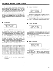
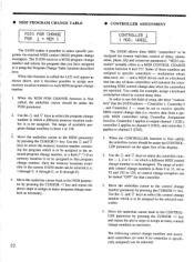
CTRI n Di y A.A 4 inn.pi CTRL 0 Di y A.A - lffi.A DELAY & CROSSOVER MODE DLY ATT. Attenuation. These parameters make it possible to independently control up to the three D1030 channels - for example, you would set the value of transmitting control change messages with control numbers Q ...through 31, 64 through 95 and 102 through 120 can be controlled in the DELAY & PARAMETRIC EQUALIZER and DELAY & CROSSOVER modes, as for...
CTRI n Di y A.A 4 inn.pi CTRL 0 Di y A.A - lffi.A DELAY & CROSSOVER MODE DLY ATT. Attenuation. These parameters make it possible to independently control up to the three D1030 channels - for example, you would set the value of transmitting control change messages with control numbers Q ...through 31, 64 through 95 and 102 through 120 can be controlled in the DELAY & PARAMETRIC EQUALIZER and DELAY & CROSSOVER modes, as for...
D1030 Owners Manual Image
Page 22
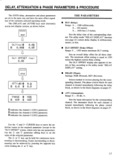
... channels require the same parameter settings, the editing procedure need only be programmed simultaneously. Any parameter changes made on the master unit will in the DELAY & CROSSOVER mode. • If more than one pin (6 ... 9) is grounded at the same time, the lowest-numbered pin takes priority. •...MIDI cable from the MIDI OUT of the master unit to match the transmit channel of the slave unit. MIDI LINK This function allows two D1030 units connected via a MIDI cable to the utility mode "MIDI CONTROL" function described on page 21. The MIDI link functions will then ...
... channels require the same parameter settings, the editing procedure need only be programmed simultaneously. Any parameter changes made on the master unit will in the DELAY & CROSSOVER mode. • If more than one pin (6 ... 9) is grounded at the same time, the lowest-numbered pin takes priority. •...MIDI cable from the MIDI OUT of the master unit to match the transmit channel of the slave unit. MIDI LINK This function allows two D1030 units connected via a MIDI cable to the utility mode "MIDI CONTROL" function described on page 21. The MIDI link functions will then ...
D1030 Owners Manual Image
Page 23
... at the cursor position. The characters accessible via the 6 and 9' keys are held briefly to allow for more convenient to create original titles for your D1030 programs, for longer than about one second. . f q h i ..i I< 1 n n o .5 P •i r st. J '' -. [ ] : . :j. + - = g: , . ' ! ? -ii• i- # ri 1 234 5 67 :39 * A SPACE can be ... display mode. • TITLE EDIT INITIAL P.E0 TITLE EDIT The Program Title Edit function allows you to have the D1030 display delay parameters in their proper order. In the peak hold mode. CA' ;.? F.' d P.
... at the cursor position. The characters accessible via the 6 and 9' keys are held briefly to allow for more convenient to create original titles for your D1030 programs, for longer than about one second. . f q h i ..i I< 1 n n o .5 P •i r st. J '' -. [ ] : . :j. + - = g: , . ' ! ? -ii• i- # ri 1 234 5 67 :39 * A SPACE can be ... display mode. • TITLE EDIT INITIAL P.E0 TITLE EDIT The Program Title Edit function allows you to have the D1030 display delay parameters in their proper order. In the peak hold mode. CA' ;.? F.' d P.
D1030 Owners Manual Image
Page 24
... the PGM parameter by pressing the CURSOR > key. Some of these controllers will appear as necessary. 22 • CONTROLLER ASSIGNMENT CONTROLLER 1 I = MEM 1 The D1030 makes it possible to control delay time. modulation wheel, data entry, etc - Controller 1, Controller 2 , and Controller 3 - to which a different memory location number is to assign as a keyboard that...
... the PGM parameter by pressing the CURSOR > key. Some of these controllers will appear as necessary. 22 • CONTROLLER ASSIGNMENT CONTROLLER 1 I = MEM 1 The D1030 makes it possible to control delay time. modulation wheel, data entry, etc - Controller 1, Controller 2 , and Controller 3 - to which a different memory location number is to assign as a keyboard that...

D1030 Owners Manual Image
Page 26
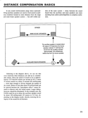
...installations. the worst possible case. Refer to meters. or 68 millimeters if the display mode is set to the example below. The D1030's DELAY & CROSSOVER mode makes accurate time alignment quick and easy to achieve, in addition to achieving optimum sound quality in Hertz With a crossover... originate primarily at the mouth of two drivers are not aligned, their output will most likely be resolved quite easily with the D1030 in almost 180 degrees phase difference - TIME ALIGNMENT BASICS Time alignment is essential to providing a high-quality programmable ele-ctronic crossover...
...installations. the worst possible case. Refer to meters. or 68 millimeters if the display mode is set to the example below. The D1030's DELAY & CROSSOVER mode makes accurate time alignment quick and easy to achieve, in addition to achieving optimum sound quality in Hertz With a crossover... originate primarily at the mouth of two drivers are not aligned, their output will most likely be resolved quite easily with the D1030 in almost 180 degrees phase difference - TIME ALIGNMENT BASICS Time alignment is essential to providing a high-quality programmable ele-ctronic crossover...
D1030 Owners Manual Image
Page 27
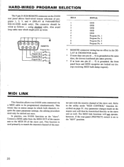
In the example case, the D1030 could be eliminated. AUXILIARY REAR SPEAKERS O Referring to the diagram ... ignored because the "precedence effect" causes listeners to discern only the initial sound, Longer delays, however, should be set to delay the auxiliary speaker sound by about 100 milliseconds (35 meters or 115 feet, depending on...about 35 meters (115 feet) from subtle unintelligibility to complete confusion. Since the speed of sound in a delay of the main system - DISTANCE COMPENSATION BASICS In any sound reinforcement setup where rearwardfiring auxiliary speakers are used ...
In the example case, the D1030 could be eliminated. AUXILIARY REAR SPEAKERS O Referring to the diagram ... ignored because the "precedence effect" causes listeners to discern only the initial sound, Longer delays, however, should be set to delay the auxiliary speaker sound by about 100 milliseconds (35 meters or 115 feet, depending on...about 35 meters (115 feet) from subtle unintelligibility to complete confusion. Since the speed of sound in a delay of the main system - DISTANCE COMPENSATION BASICS In any sound reinforcement setup where rearwardfiring auxiliary speakers are used ...

D1030 Owners Manual Image
Page 28
... kf 3 (Electronically Balanced) +4 dB 15052 18 bits 50 kHz 0 - 1.3 sec (20 µsec steps) 15: 1 - 9 and A - F Delay + 3-band PEQ Delay + crossover Program change for memory select, control change without notice. * Internal circuit delays result in an overall delay of Locations 1 - 9 A - SPECIFICATIONS Electrical Characteristics Frequency Response Dynamic Range Total Harmonic Distortion Input Number of Inputs...
... kf 3 (Electronically Balanced) +4 dB 15052 18 bits 50 kHz 0 - 1.3 sec (20 µsec steps) 15: 1 - 9 and A - F Delay + 3-band PEQ Delay + crossover Program change for memory select, control change without notice. * Internal circuit delays result in an overall delay of Locations 1 - 9 A - SPECIFICATIONS Electrical Characteristics Frequency Response Dynamic Range Total Harmonic Distortion Input Number of Inputs...

D1030 Owners Manual Image
Page 33
... 31 CH3 LOW GAIN No. CROSSOVER MODE (1) SWAY TYPE PARAMETER NUMBER (No.) = 46 - 81 No. PARAMETER NAME 82 CH1 DELAY TIME 83 CH2 DELAY TIME 84 CH3 DELAY TIME 85 DELAY OFFSET 86 CH1 ATTENUATE 87 CH2 ATTENUATE 88 CH3 ATTENUATE 89 CH1 PHASE 90 CH2 PHASE 91 CH3 PHASE 92 CH1...68 CH3 HIGH FINE 69 CH3 HIGH SLOPE No. PARAMETER NAME - No. EQ MODE PARAMETER NUMBER (No.) = 0 45 No. PARAMETER NAME 0 CH1 DELAY TIME 1 CH2 DELAY TIME 2 CH3 DELAY TIME 3 DELAY OFFSET 4 CH1 ATTENUATE 5 CH2 ATTENUATE 6 CH3 ATTENUATE 7 CH1 PHASE 8 CH2 PHASE 9 CH3 PHASE 10 CH1 PARAMETRIC EQ 11 CH2 PARAMETRIC EQ 12...
... 31 CH3 LOW GAIN No. CROSSOVER MODE (1) SWAY TYPE PARAMETER NUMBER (No.) = 46 - 81 No. PARAMETER NAME 82 CH1 DELAY TIME 83 CH2 DELAY TIME 84 CH3 DELAY TIME 85 DELAY OFFSET 86 CH1 ATTENUATE 87 CH2 ATTENUATE 88 CH3 ATTENUATE 89 CH1 PHASE 90 CH2 PHASE 91 CH3 PHASE 92 CH1...68 CH3 HIGH FINE 69 CH3 HIGH SLOPE No. PARAMETER NAME - No. EQ MODE PARAMETER NUMBER (No.) = 0 45 No. PARAMETER NAME 0 CH1 DELAY TIME 1 CH2 DELAY TIME 2 CH3 DELAY TIME 3 DELAY OFFSET 4 CH1 ATTENUATE 5 CH2 ATTENUATE 6 CH3 ATTENUATE 7 CH1 PHASE 8 CH2 PHASE 9 CH3 PHASE 10 CH1 PARAMETRIC EQ 11 CH2 PARAMETRIC EQ 12...
D1030 Owners Manual Image
Page 36
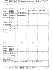
Mode 1 : OMNI ON, POLY Mode 3 : OMNI OFF, POLY Mode 2 : OMNI ON, MONO Mode 4 : OMNI OFF, MONO o : Yes x : No YAMAHA I Digital Delay Line ] Date : 10/07, 1989 Model D1030 MIDI Implementation Chart Version : 1.0 + + • : Transmitted : Recognized . • Remarks . • . • Function ... : . • . • . • : + + + :Basic Default : 1 - 16, off : 1 - 16, off : memorized . • :Channel Changed : 1 - ...
Mode 1 : OMNI ON, POLY Mode 3 : OMNI OFF, POLY Mode 2 : OMNI ON, MONO Mode 4 : OMNI OFF, MONO o : Yes x : No YAMAHA I Digital Delay Line ] Date : 10/07, 1989 Model D1030 MIDI Implementation Chart Version : 1.0 + + • : Transmitted : Recognized . • Remarks . • . • Function ... : . • . • . • : + + + :Basic Default : 1 - 16, off : 1 - 16, off : memorized . • :Channel Changed : 1 - ...