
D1030 Owners Manual Image
Page 2
... all installations. Compliance with FCC regulations does not guarantee that are coloured in accordance with other electronic devices. If this product or the device that is coloured BROWN must be used according to the instructions found in the users manual, may void your use only high quality shielded cables. Cet appareil est conforme aux prescriptions de la directive communautaire...
... all installations. Compliance with FCC regulations does not guarantee that are coloured in accordance with other electronic devices. If this product or the device that is coloured BROWN must be used according to the instructions found in the users manual, may void your use only high quality shielded cables. Cet appareil est conforme aux prescriptions de la directive communautaire...
D1030 Owners Manual Image
Page 3
...-panel controls, by using a contact-closure system, or via MIDI. The D1030 offers sound quality, programmability and functional versatility that make it ideal for a broad range of up /down loading. 1 Programs may be prepared and easily recalled when needed. ter adjust, and memory up to 50 dB or OO) for each delay channel. • Balanced +4 dB analog input and outputs. • Front panel disable and internal memory protect functions...
...-panel controls, by using a contact-closure system, or via MIDI. The D1030 offers sound quality, programmability and functional versatility that make it ideal for a broad range of up /down loading. 1 Programs may be prepared and easily recalled when needed. ter adjust, and memory up to 50 dB or OO) for each delay channel. • Balanced +4 dB analog input and outputs. • Front panel disable and internal memory protect functions...

D1030 Owners Manual Image
Page 4
... PARAMETERS & PROCEDURE ■ D/E/F: DELAY + 2-WAY CROSSOVER + SUB-WOOFER FUNCTIONAL BLOCK DIAGRAM BASIC SYSTEM CONFIGURATION 2-WAY CROSSOVER PARAMETERS & PROCEDURE DELAY, ATTENUATION & PHASE PARAMETERS & PROCEDURE THE PARAMETERS PROGRAM STORE REALTIME MIDI PARAMETER CONTROL HARD-WIRED PROGRAM SELECTION MIDI LINK UTILITY MODE FUNCTIONS TITLE EDIT DELAY DISPLAY LEVEL METER MIDI CONTROL MIDI PROGRAM CHANGE TABLE CONTROLLER ASSIGNMENT BULK OUT TIME ALIGNMENT BASICS DISTANCE COMPENSATION BASICS SPECIFICATIONS BLOCK DIAGRAM DIMENSIONS MIDI DATA FORMAT MIDI IMPLEMENTATION CHART 2 3 4 7 7 7 8 9 10...
... PARAMETERS & PROCEDURE ■ D/E/F: DELAY + 2-WAY CROSSOVER + SUB-WOOFER FUNCTIONAL BLOCK DIAGRAM BASIC SYSTEM CONFIGURATION 2-WAY CROSSOVER PARAMETERS & PROCEDURE DELAY, ATTENUATION & PHASE PARAMETERS & PROCEDURE THE PARAMETERS PROGRAM STORE REALTIME MIDI PARAMETER CONTROL HARD-WIRED PROGRAM SELECTION MIDI LINK UTILITY MODE FUNCTIONS TITLE EDIT DELAY DISPLAY LEVEL METER MIDI CONTROL MIDI PROGRAM CHANGE TABLE CONTROLLER ASSIGNMENT BULK OUT TIME ALIGNMENT BASICS DISTANCE COMPENSATION BASICS SPECIFICATIONS BLOCK DIAGRAM DIMENSIONS MIDI DATA FORMAT MIDI IMPLEMENTATION CHART 2 3 4 7 7 7 8 9 10...
D1030 Owners Manual Image
Page 5
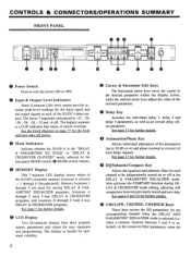
... Before Making Or Removing Connections Always turn the power OFF prior to qualified YAMAHA service personnel. PRECAUTIONS 1. Memory Backup The D1030 contains a special long-life battery that sufficient ventilation is too low to clean the unit. Refer all maintenance to connecting or disconnecting cables. 5. including the AC cord - Electrical Interference Since the D1030 contains digital circuitry, it may cause interference and noise if placed too...
... Before Making Or Removing Connections Always turn the power OFF prior to qualified YAMAHA service personnel. PRECAUTIONS 1. Memory Backup The D1030 contains a special long-life battery that sufficient ventilation is too low to clean the unit. Refer all maintenance to connecting or disconnecting cables. 5. including the AC cord - Electrical Interference Since the D1030 contains digital circuitry, it may cause interference and noise if placed too...
D1030 Owners Manual Image
Page 6
... new data. See the block diagram on or off points. The display is selected (i.e. See page 17 for the corresponding channel when the DELAY AND PARAMETRIC EQUALIZER mode is backlit for the level indicator take-off in the "DELAY & PARAMETRIC EQ (P.EQ)" or "DELAY & CROSSOVER (X-OVER)" mode, selected by the (e rear-panel MODE switch MODE switch, below). • MEMORY Display This 7-segment LED display shows which of the D1030's three outputs. CH1/LOW...
... new data. See the block diagram on or off points. The display is selected (i.e. See page 17 for the corresponding channel when the DELAY AND PARAMETRIC EQUALIZER mode is backlit for the level indicator take-off in the "DELAY & PARAMETRIC EQ (P.EQ)" or "DELAY & CROSSOVER (X-OVER)" mode, selected by the (e rear-panel MODE switch MODE switch, below). • MEMORY Display This 7-segment LED display shows which of the D1030's three outputs. CH1/LOW...
D1030 Owners Manual Image
Page 7
.... When this key is selected (memory locations A through F). le INPUT Level Control Matches the sensitivity of utility functions including program title edit, delay display mode (milliseconds, feet or meters), level meter peakhold ON/OFF, MIDI channel selection, MIDI program change table assignments, MIDI controller assignments, and bulk dump operations. e MEMORY Select, STORE and RECALL Keys Select and recall or store data in conjunction with the "IN" level indicator to set up the optimum input level for further details. DELAY & CROSSOVER mode is pressed its...
.... When this key is selected (memory locations A through F). le INPUT Level Control Matches the sensitivity of utility functions including program title edit, delay display mode (milliseconds, feet or meters), level meter peakhold ON/OFF, MIDI channel selection, MIDI program change table assignments, MIDI controller assignments, and bulk dump operations. e MEMORY Select, STORE and RECALL Keys Select and recall or store data in conjunction with the "IN" level indicator to set up the optimum input level for further details. DELAY & CROSSOVER mode is pressed its...
D1030 Owners Manual Image
Page 8
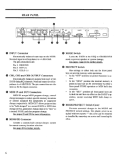
... settings to either a front-panel STORE operation or MIDI bulk data reception. • In the "KEY" position all front-panel keys are the same as for the input connector. ® MIDI IN and OUT Connectors MIDI IN accepts MIDI program change, control change messages to be removed or installed by either lock out the front panel keys or prevent memory write operations. • In the "OFF" position no effect on the D1030's operation, except receiving MIDI...
... settings to either a front-panel STORE operation or MIDI bulk data reception. • In the "KEY" position all front-panel keys are the same as for the input connector. ® MIDI IN and OUT Connectors MIDI IN accepts MIDI program change, control change messages to be removed or installed by either lock out the front panel keys or prevent memory write operations. • In the "OFF" position no effect on the D1030's operation, except receiving MIDI...

D1030 Owners Manual Image
Page 9
... by using the STORE procedure described on the LED display to actually recall and activate the selected program - rani" OFF ON Turn the [POWER] switch OFF and then ON again to the "P.EQ" position. follows: 1. sired program - the recalled program number will flash on page 18. • FUNCTIONAL BLOCK DIAGRAM INPUT +4dBm 0.0 HA PRE-EN A/D DELAY 0 ATT DELAY 0 ATT DELAY ATT SUBSONIC a a a P .E0 SUBSONIC P. DELAY & PARAMETRIC EQUALIZER MODE - The DELAY & PARAMETRIC EQUALIZER mode is...
... by using the STORE procedure described on the LED display to actually recall and activate the selected program - rani" OFF ON Turn the [POWER] switch OFF and then ON again to the "P.EQ" position. follows: 1. sired program - the recalled program number will flash on page 18. • FUNCTIONAL BLOCK DIAGRAM INPUT +4dBm 0.0 HA PRE-EN A/D DELAY 0 ATT DELAY 0 ATT DELAY ATT SUBSONIC a a a P .E0 SUBSONIC P. DELAY & PARAMETRIC EQUALIZER MODE - The DELAY & PARAMETRIC EQUALIZER mode is...

D1030 Owners Manual Image
Page 11
DELAY, ATTENUATION & PHASE PARAMETERS & PROCEDURE These parameters operate the same in all D1030 modes. ON El ON E ON 'Ile. Select the desired channel using the < and > CURSOR keys, then switch ON or OFF using the parameter editing Q and keys. 9 il, OFF indicates the channel-1 (CHI) parameter. indicates the channel-3 (CH3) parameter. allows switching the internal subsonic filter (20 Hz, -12 dB/oct.) ON or OFF for each...
DELAY, ATTENUATION & PHASE PARAMETERS & PROCEDURE These parameters operate the same in all D1030 modes. ON El ON E ON 'Ile. Select the desired channel using the < and > CURSOR keys, then switch ON or OFF using the parameter editing Q and keys. 9 il, OFF indicates the channel-1 (CHI) parameter. indicates the channel-3 (CH3) parameter. allows switching the internal subsonic filter (20 Hz, -12 dB/oct.) ON or OFF for each...
D1030 Owners Manual Image
Page 12
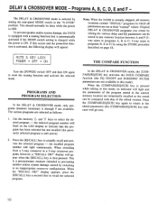
To prevent speaker and/or system damage, the D1030 is equipped with that of the program stored in this mode). PROGRAMS AND PROGRAM SELECTION In the DELAY & CROSSOVER mode, only programs (memory locations) A through F are selected as follows: 1. and keys to reset the muting function and activate the selected mode. the recalled program number will flash on page 18. MUTE KEY L POWER OFF ON Turn the [POWER] switch OFF and then ON again to select the...
To prevent speaker and/or system damage, the D1030 is equipped with that of the program stored in this mode). PROGRAMS AND PROGRAM SELECTION In the DELAY & CROSSOVER mode, only programs (memory locations) A through F are selected as follows: 1. and keys to reset the muting function and activate the selected mode. the recalled program number will flash on page 18. MUTE KEY L POWER OFF ON Turn the [POWER] switch OFF and then ON again to select the...

D1030 Owners Manual Image
Page 13
■ A/B/C: 3-CHANNEL DELAY + 3-WAY CROSSOVER • FUNCTIONAL BLOCK DIAGRAM 3WAY ri INPUT +4dBm 0.0 HA PRE-EM A/D 1=1 1=1 DELAY 0 LOW I-PF LO ATT r- See page 17 for details. 11 D/A LPF MID-LO MID-HI DELAY ATT r D/A LPF DELAY ATT HIGH HIGI LPF r D/A LPF +4dBm LOW (CHi) +4dBm MID (CH2) +4dBm HIGH (CH3) • BASIC SYSTEM CONFIGULATION CH3 (HIGH) POWER AMPLIFIERS HF HORN • CH2 (LOW) MIDRANGE CH1 (LOW) INPUT D1030 LF HORN DELAY, ATTENUATION & PHASE PARAMETERS & PROCEDURE These parameters operate the same in all D1030 modes.
■ A/B/C: 3-CHANNEL DELAY + 3-WAY CROSSOVER • FUNCTIONAL BLOCK DIAGRAM 3WAY ri INPUT +4dBm 0.0 HA PRE-EM A/D 1=1 1=1 DELAY 0 LOW I-PF LO ATT r- See page 17 for details. 11 D/A LPF MID-LO MID-HI DELAY ATT r D/A LPF DELAY ATT HIGH HIGI LPF r D/A LPF +4dBm LOW (CHi) +4dBm MID (CH2) +4dBm HIGH (CH3) • BASIC SYSTEM CONFIGULATION CH3 (HIGH) POWER AMPLIFIERS HF HORN • CH2 (LOW) MIDRANGE CH1 (LOW) INPUT D1030 LF HORN DELAY, ATTENUATION & PHASE PARAMETERS & PROCEDURE These parameters operate the same in all D1030 modes.
D1030 Owners Manual Image
Page 16
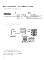
... HIGH (CH3) • BASIC SYSTEM CONFIGULATION INPUT CH3 (HIGH) POWER AMPLIFIERS CH2 (LOW) CH1 (SUB-W) HF HORN LF HORN D1030 SUB-WOOFER A full-range auxilliary speaker can be used in all D1030 modes. TET a a D/A LOW HPF LO ATT D/A HIGH HIGH LPF ATT r D/A Z -EN LPF DE-EN LPF LPF 01. • D/E/F: DELAY + 2-WAY CROSSOVER + SUB-WOOFER • FUNCTIONAL BLOCK DIAGRAM r 2WAY + SUB-IN ri L INPUT +4dBm 0.0 HA PRE-EM A/D DELAY 0 DELAY 0 DELAY 0 SUB- I-PF SUB-W ATT I-
... HIGH (CH3) • BASIC SYSTEM CONFIGULATION INPUT CH3 (HIGH) POWER AMPLIFIERS CH2 (LOW) CH1 (SUB-W) HF HORN LF HORN D1030 SUB-WOOFER A full-range auxilliary speaker can be used in all D1030 modes. TET a a D/A LOW HPF LO ATT D/A HIGH HIGH LPF ATT r D/A Z -EN LPF DE-EN LPF LPF 01. • D/E/F: DELAY + 2-WAY CROSSOVER + SUB-WOOFER • FUNCTIONAL BLOCK DIAGRAM r 2WAY + SUB-IN ri L INPUT +4dBm 0.0 HA PRE-EM A/D DELAY 0 DELAY 0 DELAY 0 SUB- I-PF SUB-W ATT I-
D1030 Owners Manual Image
Page 19
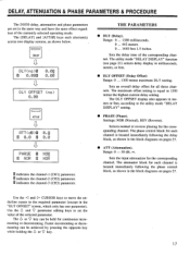
..." screen, which only has one parameter). THE PARAMETERS • DLY (Delay). The maximum offset setting is equal to the utility mode "DELAY DISPLAY" setting. • PHASE (Phase). Sets the input attenuation for continuous incre- The Q or key can be held for the corresponding channel. Range: 0 ... 1300 milliseconds. 0 ... 442 meters. 0 ... 1450 feet 1.5 inches. The utility mode "DELAY DISPLAY" function (see page 21) selects delay display in the block diagrams on pages 27. The phase control block...
..." screen, which only has one parameter). THE PARAMETERS • DLY (Delay). The maximum offset setting is equal to the utility mode "DELAY DISPLAY" setting. • PHASE (Phase). Sets the input attenuation for continuous incre- The Q or key can be held for the corresponding channel. Range: 0 ... 1300 milliseconds. 0 ... 442 meters. 0 ... 1450 feet 1.5 inches. The utility mode "DELAY DISPLAY" function (see page 21) selects delay display in the block diagrams on pages 27. The phase control block...

D1030 Owners Manual Image
Page 21
... assigned to the three D1030 channels - Editing procedure is capable of transmitting control change message can be used to select programs. Refer to the utility mode "MIDI PROGRAM CHANGE ASSIGNMENT TABLE" function described on page 22. Note: In addition to controlling parameters using the utility mode "CONTROLLER ASSIGNMENT" function described on page 22. EQ ON/OFF. High Gain. 19 LOW-FRQ LOW-G MID-FRQ MID-G MID-Q HI-FRQ HI-G Delay time. using MIDI control change messages, program change messages with control numbers...
... assigned to the three D1030 channels - Editing procedure is capable of transmitting control change message can be used to select programs. Refer to the utility mode "MIDI PROGRAM CHANGE ASSIGNMENT TABLE" function described on page 22. Note: In addition to controlling parameters using the utility mode "CONTROLLER ASSIGNMENT" function described on page 22. EQ ON/OFF. High Gain. 19 LOW-FRQ LOW-G MID-FRQ MID-G MID-Q HI-FRQ HI-G Delay time. using MIDI control change messages, program change messages with control numbers...
D1030 Owners Manual Image
Page 22
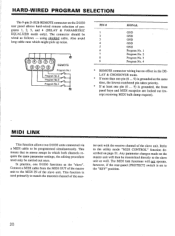
... cable. MIDI LINK This function allows two D1030 units connected via a MIDI cable to be transmitted directly to match the transmit channel of programs 1, 2, 3, and 4 (DELAY & PARAMETRIC EQUALIZER mode only). This means that in stereo setups in which might pick up noise. 54 32 9 8 7 6 REMOTE Program No.1 Program No.2 Program No.3 Program No.4 PIN # 1 2 3 4 5 6 7 8 9 SIGNAL GND GND GND GND GND Program No. 1 Program No. 2 Program No. 3 Program No. 4 • REMOTE connector wiring has no effect in t, operate...
... cable. MIDI LINK This function allows two D1030 units connected via a MIDI cable to be transmitted directly to match the transmit channel of programs 1, 2, 3, and 4 (DELAY & PARAMETRIC EQUALIZER mode only). This means that in stereo setups in which might pick up noise. 54 32 9 8 7 6 REMOTE Program No.1 Program No.2 Program No.3 Program No.4 PIN # 1 2 3 4 5 6 7 8 9 SIGNAL GND GND GND GND GND Program No. 1 Program No. 2 Program No. 3 Program No. 4 • REMOTE connector wiring has no effect in t, operate...
D1030 Owners Manual Image
Page 23
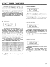
... level readings. F.' Use the Q and 9 keys to set the D1030 MIDI receive/ transmit channel. Once the utility mode has been selected, it might be entered .by pressing the STORE key. • LEVEL METER LELJEL mETEP PEA[ HOLD:OFF This function determines whether the D1030 level meters operate in milliseconds, meters or feet. After selecting the DELAY DISPLAY function, use the 6 and 9 keys to change the character at the cursor location. Use the < and > CURSOR keys...
... level readings. F.' Use the Q and 9 keys to set the D1030 MIDI receive/ transmit channel. Once the utility mode has been selected, it might be entered .by pressing the STORE key. • LEVEL METER LELJEL mETEP PEA[ HOLD:OFF This function determines whether the D1030 level meters operate in milliseconds, meters or feet. After selecting the DELAY DISPLAY function, use the 6 and 9 keys to change the character at the cursor location. Use the < and > CURSOR keys...
D1030 Owners Manual Image
Page 24
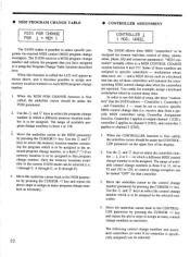
...-time control of delay, attenuation, phase, EQ and crossover parameters. Only the memory locations available in the current D1030 mode can be under the CONTROLLER parameter on the upper line of available program change data (i.e. and a MIDI device such as necessary. 22 • CONTROLLER ASSIGNMENT CONTROLLER 1 I = MEM 1 The D1030 makes it possible to receive specific MIDI control change numbers is first called, the underline cursor should be selected: In order to channel 3 (CH3). 1. Controller...
...-time control of delay, attenuation, phase, EQ and crossover parameters. Only the memory locations available in the current D1030 mode can be under the CONTROLLER parameter on the upper line of available program change data (i.e. and a MIDI device such as necessary. 22 • CONTROLLER ASSIGNMENT CONTROLLER 1 I = MEM 1 The D1030 makes it possible to receive specific MIDI control change numbers is first called, the underline cursor should be selected: In order to channel 3 (CH3). 1. Controller...

D1030 Owners Manual Image
Page 25
... D1030 data ("ALL"), the data for all programs ("MEM*"), the MIDI program change table ("PGM-TBL"), or the system setup data ("SYS"). If the "MEM" type is selected, use the 6 and 7 keys to select the particular program from which you want to dump the data or the asterisk ("MEM*") for a single program ("MEM"), all programs. Once the data to be transmitted. FOOT CTRL PORT TIME DATA ENTRY MAIN VOLUME No specific controller assigned. Control Change # Controller Assignment...
... D1030 data ("ALL"), the data for all programs ("MEM*"), the MIDI program change table ("PGM-TBL"), or the system setup data ("SYS"). If the "MEM" type is selected, use the 6 and 7 keys to select the particular program from which you want to dump the data or the asterisk ("MEM*") for a single program ("MEM"), all programs. Once the data to be transmitted. FOOT CTRL PORT TIME DATA ENTRY MAIN VOLUME No specific controller assigned. Control Change # Controller Assignment...

D1030 Owners Manual Image
Page 28
... memory select) INPUT/OUTPUT 1 - 3 7-segment LED 16-char. SPECIFICATIONS Electrical Characteristics Frequency Response Dynamic Range Total Harmonic Distortion Input Number of Inputs' Nominal Level Input Impedance Outputs Number of Outputs Nominal Level Output Impedance A/D, D/A Conversion Quantization Sampling Rate Delay Time Memory Number of approximately 0.85 msec even when DELAY TIME and DELAY OFFSET are both set to "0", or DELAY BYPASS is•engaged. 26 F Delay + 3-band PEQ Delay + crossover Program change for memory select, control change without notice. * Internal circuit delays...
... memory select) INPUT/OUTPUT 1 - 3 7-segment LED 16-char. SPECIFICATIONS Electrical Characteristics Frequency Response Dynamic Range Total Harmonic Distortion Input Number of Inputs' Nominal Level Input Impedance Outputs Number of Outputs Nominal Level Output Impedance A/D, D/A Conversion Quantization Sampling Rate Delay Time Memory Number of approximately 0.85 msec even when DELAY TIME and DELAY OFFSET are both set to "0", or DELAY BYPASS is•engaged. 26 F Delay + 3-band PEQ Delay + crossover Program change for memory select, control change without notice. * Internal circuit delays...
D1030 Owners Manual Image
Page 36
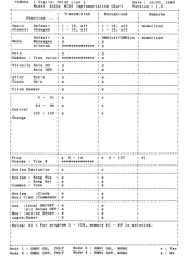
Mode 1 : OMNI ON, POLY Mode 3 : OMNI OFF, POLY Mode 2 : OMNI ON, MONO Mode 4 : OMNI OFF, MONO o : Yes x : No YAMAHA I Digital Delay Line ] Date : 10/07, 1989 Model D1030 MIDI Implementation Chart Version : 1.0 + + • : Transmitted : Recognized . • Remarks . • . • Function ... : . • . • . • : + + + :Basic Default : 1 - 16, off : 1 - 16, off : memorized . • :Channel Changed : 1 - 16, off : 1 - 16, off . • • : + + + : . • Default : x : OMNioff/OMNIon : memorized • :Mode Messages ...
Mode 1 : OMNI ON, POLY Mode 3 : OMNI OFF, POLY Mode 2 : OMNI ON, MONO Mode 4 : OMNI OFF, MONO o : Yes x : No YAMAHA I Digital Delay Line ] Date : 10/07, 1989 Model D1030 MIDI Implementation Chart Version : 1.0 + + • : Transmitted : Recognized . • Remarks . • . • Function ... : . • . • . • : + + + :Basic Default : 1 - 16, off : 1 - 16, off : memorized . • :Channel Changed : 1 - 16, off : 1 - 16, off . • • : + + + : . • Default : x : OMNioff/OMNIon : memorized • :Mode Messages ...


