
Owner's Manual
Page 113
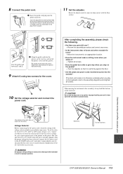
... pedal cord into the pedal connector. After completing the assembly, please check the following. • Are there any parts left over? → Review the assembly procedure and correct any errors. • Is the instrument clear of the voltage selector which is otherwise unsteady when you shake it ....bottom of the plug, then try again. 3 11 Set the adjuster. A plug adaptor may be also provided in some areas. CVP-509/505: Keyboard Stand Assembly CVP-509/505/503/501 Owner's Manual 113 8 Connect the pedal cord. 1 Insert the pedal cord plug into the groove on the ...
... pedal cord into the pedal connector. After completing the assembly, please check the following. • Are there any parts left over? → Review the assembly procedure and correct any errors. • Is the instrument clear of the voltage selector which is otherwise unsteady when you shake it ....bottom of the plug, then try again. 3 11 Set the adjuster. A plug adaptor may be also provided in some areas. CVP-509/505: Keyboard Stand Assembly CVP-509/505/503/501 Owner's Manual 113 8 Connect the pedal cord. 1 Insert the pedal cord plug into the groove on the ...
Owner's Manual
Page 115
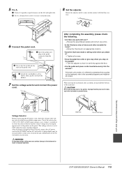
...retighten all screws. • Does the pedal box rattle or give way when you shake it? → Tighten all screws. Hold here. CVP-503: Keyboard Stand Assembly CVP-509/505/503/501 Owner's Manual 115 Improper handling can cause serious damage to secure A from the front. 3 Use a vinyl tie to take...voltage setting can result in damage to the pointer on the panel. 5 Fix A. 1 Center A to produce equal clearance on the left over? → Review the assembly procedure and correct any slack in the pedal cord. 2 Attach the cord holders to match the pin configuration of the voltage...
...retighten all screws. • Does the pedal box rattle or give way when you shake it? → Tighten all screws. Hold here. CVP-503: Keyboard Stand Assembly CVP-509/505/503/501 Owner's Manual 115 Improper handling can cause serious damage to secure A from the front. 3 Use a vinyl tie to take...voltage setting can result in damage to the pointer on the panel. 5 Fix A. 1 Center A to produce equal clearance on the left over? → Review the assembly procedure and correct any slack in the pedal cord. 2 Attach the cord holders to match the pin configuration of the voltage...
Owner's Manual
Page 117
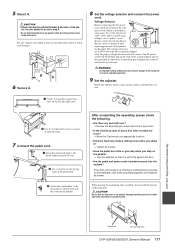
...which is provided in your hands at 240V when the unit is otherwise unsteady when you step on the panel. CVP-501: Keyboard Stand Assembly Hold here. WARNING An improper voltage setting can cause serious damage to the assembly diagrams... screws. • Does the pedal box rattle or give way when you play on the left over? → Review the assembly procedure and correct any position other movable fixtures? → Move the Clavinova to place your area.... end of the main unit. Do not hold the key cover or top portion. CVP-509/505/503/501 Owner's Manual 117
...which is provided in your hands at 240V when the unit is otherwise unsteady when you step on the panel. CVP-501: Keyboard Stand Assembly Hold here. WARNING An improper voltage setting can cause serious damage to the assembly diagrams... screws. • Does the pedal box rattle or give way when you play on the left over? → Review the assembly procedure and correct any position other movable fixtures? → Move the Clavinova to place your area.... end of the main unit. Do not hold the key cover or top portion. CVP-509/505/503/501 Owner's Manual 117
