
Owner's Manual
Page 3
... touch either surface of time at least five seconds to place heavy objects on an ATAcompatible PC flash storage card before operating the CS1D Warnings • Do not allow the unit to the faders. to damage the system. If noise occurs, use a vacuum cleaner etc. Please ... following before replacing the battery. • The performance of the PW1D power supply unit. ii Failure to use an appropriate number of the PM1D power supply unit and make sure that you experience any hearing loss or ringing in order to do so may induce a slight noise into ...
... touch either surface of time at least five seconds to place heavy objects on an ATAcompatible PC flash storage card before operating the CS1D Warnings • Do not allow the unit to the faders. to damage the system. If noise occurs, use a vacuum cleaner etc. Please ... following before replacing the battery. • The performance of the PW1D power supply unit. ii Failure to use an appropriate number of the PM1D power supply unit and make sure that you experience any hearing loss or ringing in order to do so may induce a slight noise into ...

Owner's Manual
Page 9
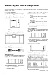
...that the mode used . • Distinguishing between the 96 channel model and 48 channel model In general, the "CS1D Operating Manual (Start-up)" is written with the 96 channel model PM1D system (the model with the DSP1D as the engine) in the display screen of . 1 DSPx2 The...faders) on the top panel, rear panel, and front panel of the PM1D system and verify that the PM1D system is operating correctly. Printing conventions in the screen. Introduction About the "CS1D Operating Manual (Start-up)" The "CS1D Operating Manual (Start-up)" is an introductory manual that explains how to...
...that the mode used . • Distinguishing between the 96 channel model and 48 channel model In general, the "CS1D Operating Manual (Start-up)" is written with the 96 channel model PM1D system (the model with the DSP1D as the engine) in the display screen of . 1 DSPx2 The...faders) on the top panel, rear panel, and front panel of the PM1D system and verify that the PM1D system is operating correctly. Printing conventions in the screen. Introduction About the "CS1D Operating Manual (Start-up)" The "CS1D Operating Manual (Start-up)" is an introductory manual that explains how to...
Owner's Manual
Page 10
...- 4 OUT - 8 OUT *: Manufactured by a Yamaha service engineer. The user must never attempt to install a card himself. PHANTOM MASTER ON +48V OFF POWER ON/ OFF ANALOG INPUT BOX The following types of cards can be installed in the PM1D system, such as audio signal input/output, mixing, and... + four AD cards installed Cards can accommodate eight DA cards (LMY4-DA). 1 2 3 4 5 6 7 8 OUTPUT UNIT NO. Console (CS1D) The mixing operations, scene memory/library operations, and various editing operations of engine: the 96 channel DSP1D-EX, and the 48 channel DSP1D. INPUT SELECTOR...
...- 4 OUT - 8 OUT *: Manufactured by a Yamaha service engineer. The user must never attempt to install a card himself. PHANTOM MASTER ON +48V OFF POWER ON/ OFF ANALOG INPUT BOX The following types of cards can be installed in the PM1D system, such as audio signal input/output, mixing, and... + four AD cards installed Cards can accommodate eight DA cards (LMY4-DA). 1 2 3 4 5 6 7 8 OUTPUT UNIT NO. Console (CS1D) The mixing operations, scene memory/library operations, and various editing operations of engine: the 96 channel DSP1D-EX, and the 48 channel DSP1D. INPUT SELECTOR...
Owner's Manual
Page 15
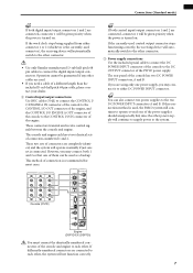
...ENGINE A 1 IN 1 IN 1 IN OUT 2 IN OUT 2 IN OUT 2 IN OUT OUT OUT Console (CS1D) MIDI IN OUT THRU CONTROL I /O ENGINE A OUT connector of the console to connect the digital input/output ...that one of the power supplies should unexpectedly fail, since the other connector. • Use only Yamaha-manufactured D-sub half pitch 68 pin cables to the DC OUTPUT connector of them can also connect ... of the console to either connector 1 or 2 (whichever is the currently-used , the PM1D system will automatically switch to the other cables are used as a backup. These connectors transmit ...
...ENGINE A 1 IN 1 IN 1 IN OUT 2 IN OUT 2 IN OUT 2 IN OUT OUT OUT Console (CS1D) MIDI IN OUT THRU CONTROL I /O ENGINE A OUT connector of the console to connect the digital input/output ...that one of the power supplies should unexpectedly fail, since the other connector. • Use only Yamaha-manufactured D-sub half pitch 68 pin cables to the DC OUTPUT connector of them can also connect ... of the console to either connector 1 or 2 (whichever is the currently-used , the PM1D system will automatically switch to the other cables are used as a backup. These connectors transmit ...
Owner's Manual
Page 19
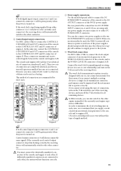
In the same way, connect the CONTROL I/ O ENGINE B IN and OUT connectors of the console to either connector 1 or 2 (whichever is the currently-used , the PM1D system will continue to operate even if one of connection is recommended for most cases. 22 22 22 22 MIDI IN OUT THRU CONTROL I/O CONSOLE 1 ... REMOTE RS-422 USB GPI WORD CLOCK IN CONSOLE CONTROL I/O ENGINE B ENGINE A 1 IN 1 IN 1 IN OUT 2 IN OUT 2 IN OUT 2 IN OUT OUT OUT Console (CS1D) MIDI IN OUT THRU CONTROL I/O CONSOLE 1 IN OUT 2 IN PC CONTROL RS-232-C OUT REMOTE RS-422 USB GPI WORD CLOCK IN 75Ω OFF...
In the same way, connect the CONTROL I/ O ENGINE B IN and OUT connectors of the console to either connector 1 or 2 (whichever is the currently-used , the PM1D system will continue to operate even if one of connection is recommended for most cases. 22 22 22 22 MIDI IN OUT THRU CONTROL I/O CONSOLE 1 ... REMOTE RS-422 USB GPI WORD CLOCK IN CONSOLE CONTROL I/O ENGINE B ENGINE A 1 IN 1 IN 1 IN OUT 2 IN OUT 2 IN OUT 2 IN OUT OUT OUT Console (CS1D) MIDI IN OUT THRU CONTROL I/O CONSOLE 1 IN OUT 2 IN PC CONTROL RS-232-C OUT REMOTE RS-422 USB GPI WORD CLOCK IN 75Ω OFF...
Owner's Manual
Page 22
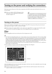
... you will be lost. Before turning on the engine (DSP1D) or the console power supply (PW1D), you saved will operate the console. Failing to "CS1D Reference Manual (Software)." Each device must be comfortably viewed at the angle from their initial state, or if you have finished connecting the various... Manual (Start-up the PM1D system for the first time, but also after the power was turned off. Turning on the power and verifying the connections Here's how to power-on each device. 14 You must wait at the right of the CS1D are in this waiting period may cause ...
... you will be lost. Before turning on the engine (DSP1D) or the console power supply (PW1D), you saved will operate the console. Failing to "CS1D Reference Manual (Software)." Each device must be comfortably viewed at the angle from their initial state, or if you have finished connecting the various... Manual (Start-up the PM1D system for the first time, but also after the power was turned off. Turning on the power and verifying the connections Here's how to power-on each device. 14 You must wait at the right of the CS1D are in this waiting period may cause ...
Owner's Manual
Page 23
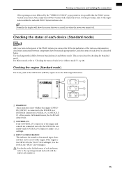
... used on the power and verifying the connections If the opening screen is followed by the "VERSION CHECK" popup window, it is possible that the PM1D system version is the DSP1D-EX, the "96CH" LED will light. {For the DSP1D, the "48CH" LED will light. 3 INPUT CONFIGURATION This ... (either 1 or 2) will light.} For details on the lit/dark status of each device (Standard mode) DSPx1 After you turn on the power of the PM1D system, you can be lit. 2 CONTROL I/O If the CONTROL I/O connectors of each device as described below. ENGINE ID A B CONTROL I/O 1 2 INPUT CONFIGURATION 48CH 96CH...
... used on the power and verifying the connections If the opening screen is followed by the "VERSION CHECK" popup window, it is possible that the PM1D system version is the DSP1D-EX, the "96CH" LED will light. {For the DSP1D, the "48CH" LED will light. 3 INPUT CONFIGURATION This ... (either 1 or 2) will light.} For details on the lit/dark status of each device (Standard mode) DSPx1 After you turn on the power of the PM1D system, you can be lit. 2 CONTROL I/O If the CONTROL I/O connectors of each device as described below. ENGINE ID A B CONTROL I/O 1 2 INPUT CONFIGURATION 48CH 96CH...
Owner's Manual
Page 24
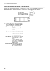
... the ID number of that the engine is powered-on the engine to an OUTPUT connector of the engine) INPUT UNIT ID 1 2 3 4 5 6 7 8 INPUT UNIT NO. CS1D Operating Manual (Start-up) Checking the analog input unit (Standard mode) If the AI8 input unit is correctly connected to the engine, the INPUT UNIT... the AI8 will appear in the INPUT UNIT ID indicator. • E1 The AI8 is connected to which the AI8 is not synchronized with the PM1D system. Re-connect it to an INPUT connector. • E3 Either the cable connected to the INPUT 1 connector of the engine. Make sure that unit...
... the ID number of that the engine is powered-on the engine to an OUTPUT connector of the engine) INPUT UNIT ID 1 2 3 4 5 6 7 8 INPUT UNIT NO. CS1D Operating Manual (Start-up) Checking the analog input unit (Standard mode) If the AI8 input unit is correctly connected to the engine, the INPUT UNIT... the AI8 will appear in the INPUT UNIT ID indicator. • E1 The AI8 is connected to which the AI8 is not synchronized with the PM1D system. Re-connect it to an INPUT connector. • E3 Either the cable connected to the INPUT 1 connector of the engine. Make sure that unit...
Owner's Manual
Page 25
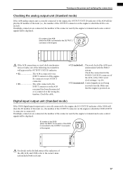
.../ OFF For details on the lit/dark status of the indicators of the AI8, AO8, and DIO8, refer to the owner's manuals included with the PM1D system. Turning on the power and verifying the connections Checking the analog output unit (Standard mode) If the AO8 analog output unit is correctly connected... to the OUTPUT 3 connector of the engine) I/O UNIT ID I /O UNIT ID indicator of the DIO8 will show the ID number of the AO8, or the CS1D word clock settings (→p.24). • UC (unconnected) .
.../ OFF For details on the lit/dark status of the indicators of the AI8, AO8, and DIO8, refer to the owner's manuals included with the PM1D system. Turning on the power and verifying the connections Checking the analog output unit (Standard mode) If the AO8 analog output unit is correctly connected... to the OUTPUT 3 connector of the engine) I/O UNIT ID I /O UNIT ID indicator of the DIO8 will show the ID number of the AO8, or the CS1D word clock settings (→p.24). • UC (unconnected) .
Owner's Manual
Page 26
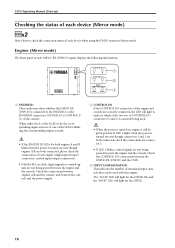
Engines (Mirror mode) The front panel of each device when using the PM1D system in use. If one of the LEDs is blinking, the corresponding engine is ready. • If the ENGINE ID LEDs for the DSP1D-EX, ... indicators show whether the DSP1D-EX {DSP1D} is currently being passed between the DSP1D-EX {DSP1D} and the CS1D. 3 INPUT CONFIGURATION This indicates the number of monaural input channels that can be given priority. CS1D Operating Manual (Start-up) Checking the status of each device (Mirror mode) DSPx2 Here's how to check...
Engines (Mirror mode) The front panel of each device when using the PM1D system in use. If one of the LEDs is blinking, the corresponding engine is ready. • If the ENGINE ID LEDs for the DSP1D-EX, ... indicators show whether the DSP1D-EX {DSP1D} is currently being passed between the DSP1D-EX {DSP1D} and the CS1D. 3 INPUT CONFIGURATION This indicates the number of monaural input channels that can be given priority. CS1D Operating Manual (Start-up) Checking the status of each device (Mirror mode) DSPx2 Here's how to check...

Owner's Manual
Page 29
.... Check the connections of the DIO8's WORD CLOCK IN connector, or the word clock setting of the CS1D (→p.28). • ID number and A (or b) displayed alternately Since control signals from the CS1D forcibly switched the valid engine to which the INPUT A connector of the DIO8 is connected), and a ...dot ( . ) will show one of the following error displays. • UL (unlocked) ....The word clock of the DIO8 is not synchronized with the PM1D system. This display...
.... Check the connections of the DIO8's WORD CLOCK IN connector, or the word clock setting of the CS1D (→p.28). • ID number and A (or b) displayed alternately Since control signals from the CS1D forcibly switched the valid engine to which the INPUT A connector of the DIO8 is connected), and a ...dot ( . ) will show one of the following error displays. • UL (unlocked) ....The word clock of the DIO8 is not synchronized with the PM1D system. This display...

Owner's Manual
Page 30
... the system, you can successively access different screens within that will automatically remember them. (However if you modify the configuration of the PM1D (which is used with one console is used with two engines. [Procedure] 1. If you are connected to each other ), and set the...of the LCD FUNCTION ACCESS block are connected to each other . LCD FUNCTION ACCESS block [SYS/W.CLOCK] switch Hint The switches of the PM1D system and how the components are using Mirror mode, please proceed to access the screen shown on the following page. Basic settings (Standard mode...
... the system, you can successively access different screens within that will automatically remember them. (However if you modify the configuration of the PM1D (which is used with one console is used with two engines. [Procedure] 1. If you are connected to each other ), and set the...of the LCD FUNCTION ACCESS block are connected to each other . LCD FUNCTION ACCESS block [SYS/W.CLOCK] switch Hint The switches of the PM1D system and how the components are using Mirror mode, please proceed to access the screen shown on the following page. Basic settings (Standard mode...
Owner's Manual
Page 32
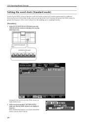
CS1D Operating Manual (Start-up) Setting the word clock (Standard mode) In order for the word clock of... several times to as the sampling rate or sampling frequency. [Procedure] 1. LCD FUNCTION ACCESS block [SYS/W.CLOCK] switch Settings for the PM1D system to function, word clock (audio system clock) synchronization must be established between all devices of this screen. 2. In general, the... is referred to access the following screen. If the ADVANCED button is on instead of the PM1D system are made in green). In the screen area marked "SETTING LEVEL," make sure that will operate the...
CS1D Operating Manual (Start-up) Setting the word clock (Standard mode) In order for the word clock of... several times to as the sampling rate or sampling frequency. [Procedure] 1. LCD FUNCTION ACCESS block [SYS/W.CLOCK] switch Settings for the PM1D system to function, word clock (audio system clock) synchronization must be established between all devices of this screen. 2. In general, the... is referred to access the following screen. If the ADVANCED button is on instead of the PM1D system are made in green). In the screen area marked "SETTING LEVEL," make sure that will operate the...

Owner's Manual
Page 33
If you are changed, but also when the word clock setting is switched on , you can occur not only when PM1D system internal settings are using an external clock generator as the word clock master. If when you change the word clock settings, the AI8 or ... detailed word clock settings. 3. Basic settings (Standard mode) 25 Such a change the word clock settings, noise may be heard from the output jacks of the CS1D and AO8, particularly if an MY8-AT digital I/O card is not synchronized, check the connections between the engine and console, and the connections between the...
If you are changed, but also when the word clock setting is switched on , you can occur not only when PM1D system internal settings are using an external clock generator as the word clock master. If when you change the word clock settings, the AI8 or ... detailed word clock settings. 3. Basic settings (Standard mode) 25 Such a change the word clock settings, noise may be heard from the output jacks of the CS1D and AO8, particularly if an MY8-AT digital I/O card is not synchronized, check the connections between the engine and console, and the connections between the...

Owner's Manual
Page 34
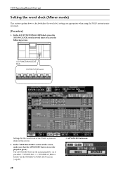
LCD FUNCTION ACCESS block [SYS/W.CLOCK] switch This is the SYSTEM CONNECTION screen, in Mirror mode. Selecting the operation mode (Mirror mode) [Procedure] 1. In the LCD FUNCTION ACCESS block, press the [SYS/W.CLOCK] switch several times to select the operation mode and word clock master when using the PM1D system in which you can check the connection status of each device, and select the operation mode. 26 Basic settings (Mirror mode) DSPx2 This section explains how to access the following screen.
LCD FUNCTION ACCESS block [SYS/W.CLOCK] switch This is the SYSTEM CONNECTION screen, in Mirror mode. Selecting the operation mode (Mirror mode) [Procedure] 1. In the LCD FUNCTION ACCESS block, press the [SYS/W.CLOCK] switch several times to select the operation mode and word clock master when using the PM1D system in which you can check the connection status of each device, and select the operation mode. 26 Basic settings (Mirror mode) DSPx2 This section explains how to access the following screen.

Owner's Manual
Page 35
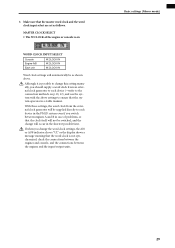
... clock will be produced from the output jacks of the number. If the connection is broken, an "x" symbol will not be displayed instead of the CS1D or AO8 (in particular if an MY8-AT digital I/O card is connected to select the jack number (1 or 2) that the OPER- This indicates the type... a button in Mirror mode, use this time, noise may be displayed instead of "OPERATION MODE." This indicates the type of engines A and B. When using the PM1D system in the jack area to the previous screen.
... clock will be produced from the output jacks of the number. If the connection is broken, an "x" symbol will not be displayed instead of the CS1D or AO8 (in particular if an MY8-AT digital I/O card is connected to select the jack number (1 or 2) that the OPER- This indicates the type... a button in Mirror mode, use this time, noise may be displayed instead of "OPERATION MODE." This indicates the type of engines A and B. When using the PM1D system in the jack area to the previous screen.
Owner's Manual
Page 36
... LEVEL" section of the PM1D system are appropriate when using the PM1D system in mirror mode. [Procedure] 1. In the LCD FUNCTION ACCESS block, press the [SYS/W.CLOCK] switch several times to check whether the word clock settings are made in this screen. 2. The ADVANCED button will automatically be on CS1D Operating Manual (Start...
... LEVEL" section of the PM1D system are appropriate when using the PM1D system in mirror mode. [Procedure] 1. In the LCD FUNCTION ACCESS block, press the [SYS/W.CLOCK] switch several times to check whether the word clock settings are made in this screen. 2. The ADVANCED button will automatically be on CS1D Operating Manual (Start...
Owner's Manual
Page 37
... between the engines and console, and the connections between engines A and B in case of the engine or console is possible to each device in the PM1D system even if you should supply a word clock from the external clock generator will occur in a stable manner.
... between the engines and console, and the connections between engines A and B in case of the engine or console is possible to each device in the PM1D system even if you should supply a word clock from the external clock generator will occur in a stable manner.

Owner's Manual
Page 38
... input/output units and the engine to verify that you have performed the following actions. • Connect the various components that are part of the PM1D system (→p.6-13) • Use the indicators/LEDs of an input unit connected to the DSP1D-EX {DSP1D} engine. Connect an input source to the... of the console (or to the MONITOR A headphone jack) m Turn on the power in the order of input unit → DSP1D-EX {DSP1D} engine → CS1D console → monitor system m Patch the input unit to an input channel m Press the [CUE] switch of the input channel m Check whether the signal is...
... input/output units and the engine to verify that you have performed the following actions. • Connect the various components that are part of the PM1D system (→p.6-13) • Use the indicators/LEDs of an input unit connected to the DSP1D-EX {DSP1D} engine. Connect an input source to the... of the console (or to the MONITOR A headphone jack) m Turn on the power in the order of input unit → DSP1D-EX {DSP1D} engine → CS1D console → monitor system m Patch the input unit to an input channel m Press the [CUE] switch of the input channel m Check whether the signal is...

Owner's Manual
Page 41
Turn on the power in the order of the CS1D console. [Procedure] 1. In the LCD FUNCTION ACCESS block, press the INPUT [PATCH] switch several times to the PM1D system. This operation is the INPUT PATCH screen, where signals from an input unit or effect return can be input to access the following screen... channel Simply connecting a source to an input unit does not cause that signal to be patched to input channels of the PM1D system. In order to send signals to the PM1D system, you must assign (patch) the input jacks of the input unit to input channels. 33 LCD FUNCTION ACCESS block ...
Turn on the power in the order of the CS1D console. [Procedure] 1. In the LCD FUNCTION ACCESS block, press the INPUT [PATCH] switch several times to the PM1D system. This operation is the INPUT PATCH screen, where signals from an input unit or effect return can be input to access the following screen... channel Simply connecting a source to an input unit does not cause that signal to be patched to input channels of the PM1D system. In order to send signals to the PM1D system, you must assign (patch) the input jacks of the input unit to input channels. 33 LCD FUNCTION ACCESS block ...
