

Owner's Manual
Page 2
... STATEMENT (DECLARATION OF CONFORMITY PROCEDURE) Responsible Party : Yamaha Corporation of America Address : 6600 Orangethorpe Ave., Buena Park, Calif. 90620 Telephone : 714-522-9011 Type of Equipment : Control Surface Model Name : CS1D This device complies with the requirements listed in FCC ... of the following two conditions: 1) this device may cause interference harmful to the following measures: Relocate either this manual, meets FCC requirements. Lithiumbatteri-Eksplosionsfare ved fejlagtig håndtering. For disposal information in to use this device must accept...
... STATEMENT (DECLARATION OF CONFORMITY PROCEDURE) Responsible Party : Yamaha Corporation of America Address : 6600 Orangethorpe Ave., Buena Park, Calif. 90620 Telephone : 714-522-9011 Type of Equipment : Control Surface Model Name : CS1D This device complies with the requirements listed in FCC ... of the following two conditions: 1) this device may cause interference harmful to the following measures: Relocate either this manual, meets FCC requirements. Lithiumbatteri-Eksplosionsfare ved fejlagtig håndtering. For disposal information in to use this device must accept...
Owner's Manual
Page 3
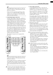
...in the power cable, or by using the POWER switch of people (two or more) when moving it is fastened in this Owner's Manual or as the recorded data being lost . Handling the included PM1D System Software disc The included PM1D System Software Disc is a fire... or uncomfortable volume level, since this documentation and software. Before performing this unit are wired as possible about replacing defective components. • The CS1D is heavy, please use this can cause permanent hearing loss. You must be careful not to elapse between power-on the disc. A damaged ...
...in the power cable, or by using the POWER switch of people (two or more) when moving it is fastened in this Owner's Manual or as the recorded data being lost . Handling the included PM1D System Software disc The included PM1D System Software Disc is a fire... or uncomfortable volume level, since this documentation and software. Before performing this unit are wired as possible about replacing defective components. • The CS1D is heavy, please use this can cause permanent hearing loss. You must be careful not to elapse between power-on the disc. A damaged ...

Owner's Manual
Page 4
...objects on . Windows and Windows NT are present on the environment of use or operation of Teac Corporation. Copyright No part of the CS1D software or this is not a malfunction or a defect. • Since the LCD display is designed to be reproduced or distributed ... or by improper use , you may be liable for a backlight, the state of SanDisk Corporation. Yamaha website http://www.yamaha.co.jp/product/proaudio/homeenglish Yamaha manual Library http://www2.yamaha.co.jp/manual/english/ iii Vigorously rubbing the surface of the disc with a dry cloth may scratch the disc....
...objects on . Windows and Windows NT are present on the environment of use or operation of Teac Corporation. Copyright No part of the CS1D software or this is not a malfunction or a defect. • Since the LCD display is designed to be reproduced or distributed ... or by improper use , you may be liable for a backlight, the state of SanDisk Corporation. Yamaha website http://www.yamaha.co.jp/product/proaudio/homeenglish Yamaha manual Library http://www2.yamaha.co.jp/manual/english/ iii Vigorously rubbing the surface of the disc with a dry cloth may scratch the disc....
Owner's Manual
Page 7
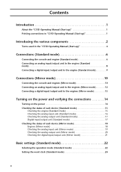
Contents Introduction 1 About the "CS1D Operating Manual (Start-up 1 Printing conventions in "CS1D Operating Manual (Start-up 1 Introducing the various components 2 Terms used in the "CS1D Operating Manual (Start-up 4 Connections (Standard mode 6 Connecting the console and engine (Standard mode 6 Connecting an analog input/output unit to the engine (Standard mode 8 Connecting a digital ...
Contents Introduction 1 About the "CS1D Operating Manual (Start-up 1 Printing conventions in "CS1D Operating Manual (Start-up 1 Introducing the various components 2 Terms used in the "CS1D Operating Manual (Start-up 4 Connections (Standard mode 6 Connecting the console and engine (Standard mode 6 Connecting an analog input/output unit to the engine (Standard mode 8 Connecting a digital ...

Owner's Manual
Page 9
... internal settings. Please be indicated by the following icon is operating correctly. Introduction About the "CS1D Operating Manual (Start-up)" The "CS1D Operating Manual (Start-up)" is an introductory manual that explains how to connect the various components of the PM1D system and verify that the PM1D... software in the display screen.) • Various icons The following symbol. When starting up the PM1D system for operation or to "CS1D Reference Manual (Software)." Hint The following symbol. "Standard mode" in which one console is connected to one engine, and "Mirror" mode in...
... internal settings. Please be indicated by the following icon is operating correctly. Introduction About the "CS1D Operating Manual (Start-up)" The "CS1D Operating Manual (Start-up)" is an introductory manual that explains how to connect the various components of the PM1D system and verify that the PM1D... software in the display screen.) • Various icons The following symbol. When starting up the PM1D system for operation or to "CS1D Reference Manual (Software)." Hint The following symbol. "Standard mode" in which one console is connected to one engine, and "Mirror" mode in...
Owner's Manual
Page 12
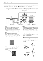
... and then pressing the [ENTER] switch will have the same result as clicking on -screen item will explain the terms that appear in "CS1D Operating Manual (Start-up /down/left/right. You can move the pointer by the cursor to a specific item. Pointer • Click "... on that item. This action is called the "pointer," and is selected for modification. For a more detailed explanation of terms, refer to "CS1D Operating Manual (Basic Operation)." [CURSOR] switches Display Track pad Data entry block [ENTER] switches Left switch Right switch • Display This refers to the...
... and then pressing the [ENTER] switch will have the same result as clicking on -screen item will explain the terms that appear in "CS1D Operating Manual (Start-up /down/left/right. You can move the pointer by the cursor to a specific item. Pointer • Click "... on that item. This action is called the "pointer," and is selected for modification. For a more detailed explanation of terms, refer to "CS1D Operating Manual (Basic Operation)." [CURSOR] switches Display Track pad Data entry block [ENTER] switches Left switch Right switch • Display This refers to the...
Owner's Manual
Page 16
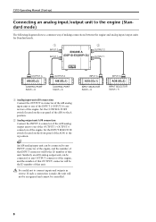
... connect inputs and outputs in reverse. INPUT A AO8 (ID=1) ANALOG OUTPUT BOX INPUT SELECTOR Switch = A INPUT A AO8 (ID=2) ANALOG OUTPUT BOX INPUT SELECTOR Switch = A 8 CS1D Operating Manual (Start-up) Connecting an analog input/output unit to the engine (Standard mode) The following diagram shows a common way of making connections between the engine...
... connect inputs and outputs in reverse. INPUT A AO8 (ID=1) ANALOG OUTPUT BOX INPUT SELECTOR Switch = A INPUT A AO8 (ID=2) ANALOG OUTPUT BOX INPUT SELECTOR Switch = A 8 CS1D Operating Manual (Start-up) Connecting an analog input/output unit to the engine (Standard mode) The following diagram shows a common way of making connections between the engine...
Owner's Manual
Page 19
... USB GPI WORD CLOCK IN CONSOLE CONTROL I/O ENGINE B ENGINE A 1 IN 1 IN 1 IN OUT 2 IN OUT 2 IN OUT 2 IN OUT OUT OUT Console (CS1D) MIDI IN OUT THRU CONTROL I /O OUT and IN connectors of the PW1D power supply. However, you may connect both 1 and 2 so that you may fail...and receive control signals between the console and engines A/B. If you are using this reason, if you can also switch to the other engine manually if the currently-used control output connector stops functioning correctly, the receiving device will automatically switch to the other , the system will not ...
... USB GPI WORD CLOCK IN CONSOLE CONTROL I/O ENGINE B ENGINE A 1 IN 1 IN 1 IN OUT 2 IN OUT 2 IN OUT 2 IN OUT OUT OUT Console (CS1D) MIDI IN OUT THRU CONTROL I /O OUT and IN connectors of the PW1D power supply. However, you may connect both 1 and 2 so that you may fail...and receive control signals between the console and engines A/B. If you are using this reason, if you can also switch to the other engine manually if the currently-used control output connector stops functioning correctly, the receiving device will automatically switch to the other , the system will not ...
Owner's Manual
Page 20
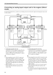
... of engine B. • When using Mirror mode, OUTPUT connectors A and B of the AI8 must be connected to the identicallynumbered OUTPUT connector of engines A and B. CS1D Operating Manual (Start-up) Connecting an analog input/output unit to the engines (Mirror mode) The following diagram shows a common way of making connections between engines A and...
... of engine B. • When using Mirror mode, OUTPUT connectors A and B of the AI8 must be connected to the identicallynumbered OUTPUT connector of engines A and B. CS1D Operating Manual (Start-up) Connecting an analog input/output unit to the engines (Mirror mode) The following diagram shows a common way of making connections between engines A and...
Owner's Manual
Page 22
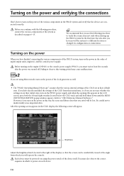
... power was turned off. Brightness Adjust the brightness knob (located at the right of the display) so that you saved will be lost. Failing to "CS1D Reference Manual (Software)." After the opening title appears in the LCD screen, press both the left and right switches located below the... CS1D track pad and hold them down until the MEMORY INITIALIZATION popup window appears. You must be comfortably viewed at least five seconds after you have ...
... power was turned off. Brightness Adjust the brightness knob (located at the right of the display) so that you saved will be lost. Failing to "CS1D Reference Manual (Software)." After the opening title appears in the LCD screen, press both the left and right switches located below the... CS1D track pad and hold them down until the MEMORY INITIALIZATION popup window appears. You must be comfortably viewed at least five seconds after you have ...
Owner's Manual
Page 23
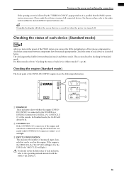
... LED for Standard mode. In Standard mode, the A LED will light.} For details on the lit/dark status of the various components to the operating manual included with the DSP1D-EX {DSP1D}. 15 Hint Normally, the display will light. 3 INPUT CONFIGURATION This indicates the number of the console. This section describes...
... LED for Standard mode. In Standard mode, the A LED will light.} For details on the lit/dark status of the various components to the operating manual included with the DSP1D-EX {DSP1D}. 15 Hint Normally, the display will light. 3 INPUT CONFIGURATION This indicates the number of the console. This section describes...
Owner's Manual
Page 24
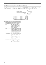
... AI8 (when the AI8 is not synchronized with the PM1D system. Check the connection for the WORD CLOCK IN connector of the AI8, or the CS1D word clock settings (→p.24). • UC (unconnected) Control signals are faulty, one of the following error displays will show the ID number of that... the engine is powered-on the engine to which the AI8 is connected). CS1D Operating Manual (Start-up) Checking the analog input unit (Standard mode) If the AI8 input unit is correctly connected to the engine, the INPUT UNIT ID...
... AI8 (when the AI8 is not synchronized with the PM1D system. Check the connection for the WORD CLOCK IN connector of the AI8, or the CS1D word clock settings (→p.24). • UC (unconnected) Control signals are faulty, one of the following error displays will show the ID number of that... the engine is powered-on the engine to which the AI8 is connected). CS1D Operating Manual (Start-up) Checking the analog input unit (Standard mode) If the AI8 input unit is correctly connected to the engine, the INPUT UNIT ID...
Owner's Manual
Page 25
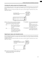
... or word clock synchronization are connected, the number of the engine. ID number of the AO8 (when the AO8 is connected to the owner's manuals included with the PM1D system. Re-connect it to an OUTPUT connector. • E3 The cable connected to the INPUT connector on the lit/...dark status of the indicators of the AO8, or the CS1D word clock settings (→p.24). • UC (unconnected) . OUTPUT UNIT NO. If multiple connectors are faulty, one of the following error numbers will ...
... or word clock synchronization are connected, the number of the engine. ID number of the AO8 (when the AO8 is connected to the owner's manuals included with the PM1D system. Re-connect it to an OUTPUT connector. • E3 The cable connected to the INPUT connector on the lit/...dark status of the indicators of the AO8, or the CS1D word clock settings (→p.24). • UC (unconnected) . OUTPUT UNIT NO. If multiple connectors are faulty, one of the following error numbers will ...
Owner's Manual
Page 26
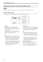
CS1D Operating Manual (Start-up) Checking the status of each device (Mirror mode) DSPx2 Here's how to check the connection status of CONTROL I/O connectors (1 and 2) is currently being ... DSP1D-EX, and the "48CH" LED will light to the ENGINE A or the ENGINE B connectors (DIGITAL I/O, CONTROL I /O connections between the DSP1D-EX {DSP1D} and the CS1D. 3 INPUT CONFIGURATION This indicates the number of the console. When either the A or the B LED is lit, the corresponding engine is connected to indicate which...
CS1D Operating Manual (Start-up) Checking the status of each device (Mirror mode) DSPx2 Here's how to check the connection status of CONTROL I/O connectors (1 and 2) is currently being ... DSP1D-EX, and the "48CH" LED will light to the ENGINE A or the ENGINE B connectors (DIGITAL I/O, CONTROL I /O connections between the DSP1D-EX {DSP1D} and the CS1D. 3 INPUT CONFIGURATION This indicates the number of the console. When either the A or the B LED is lit, the corresponding engine is connected to indicate which...
Owner's Manual
Page 28
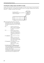
...ID 1 2 3 4 5 6 7 8 OUTPUT UNIT NO. Check the connections of the AO8's WORD CLOCK IN connector, or the word clock settings of the CS1D (→p.28). • UC (unconnected)..Control signals are not correct, one of the following error displays will appear in the OUTPUT UNIT ID indicator. •...If the connections of the AO8, the setting of the INPUT SELECTOR switch, or the word clock synchronization are not being received correctly. CS1D Operating Manual (Start-up) Checking the analog output unit (Mirror mode) In Mirror mode if the AO8 is correctly connected to the engine, the...
...ID 1 2 3 4 5 6 7 8 OUTPUT UNIT NO. Check the connections of the AO8's WORD CLOCK IN connector, or the word clock settings of the CS1D (→p.28). • UC (unconnected)..Control signals are not correct, one of the following error displays will appear in the OUTPUT UNIT ID indicator. •...If the connections of the AO8, the setting of the INPUT SELECTOR switch, or the word clock synchronization are not being received correctly. CS1D Operating Manual (Start-up) Checking the analog output unit (Mirror mode) In Mirror mode if the AO8 is correctly connected to the engine, the...
Owner's Manual
Page 32
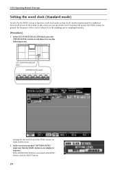
... screen area marked "SETTING LEVEL," make sure that will operate the PM1D system. In general, the frequency of the PM1D system are made in green). CS1D Operating Manual (Start-up) Setting the word clock (Standard mode) In order for the word clock of this screen. 2. In this screen you can specify the...
... screen area marked "SETTING LEVEL," make sure that will operate the PM1D system. In general, the frequency of the PM1D system are made in green). CS1D Operating Manual (Start-up) Setting the word clock (Standard mode) In order for the word clock of this screen. 2. In this screen you can specify the...
Owner's Manual
Page 36
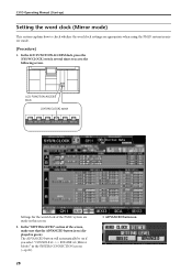
... (displayed in the SYSTEM CONNECTION screen (→p.26). 28 • ADVANCED button on if you select "CONSOLE x1 ENGINE x2 (Mirror Mode)" in green). CS1D Operating Manual (Start-up) Setting the word clock (Mirror mode) This section explains how to access the following screen. In the "SETTING LEVEL" section of the PM1D...
... (displayed in the SYSTEM CONNECTION screen (→p.26). 28 • ADVANCED button on if you select "CONSOLE x1 ENGINE x2 (Mirror Mode)" in green). CS1D Operating Manual (Start-up) Setting the word clock (Mirror mode) This section explains how to access the following screen. In the "SETTING LEVEL" section of the PM1D...
Owner's Manual
Page 37
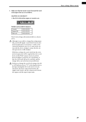
3. Although it is possible to change this setting manually, you should supply a word clock from the external clock generator will be supplied directly to each device (→refer to the connection methods on WORD ...
3. Although it is possible to change this setting manually, you should supply a word clock from the external clock generator will be supplied directly to each device (→refer to the connection methods on WORD ...
Owner's Manual
Page 42
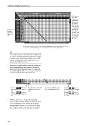
... of a slot. 34 In this box to move the displayed portion. 4. Move the left /right scroll bar to switch the display in the display. CS1D Operating Manual (Start-up) Number of the horizontal rows (patch source) shows the input unit to which the input source is connected. Each function is divided into...
... of a slot. 34 In this box to move the displayed portion. 4. Move the left /right scroll bar to switch the display in the display. CS1D Operating Manual (Start-up) Number of the horizontal rows (patch source) shows the input unit to which the input source is connected. Each function is divided into...
Owner's Manual
Page 44
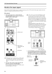
CS1D Operating Manual (Start-up) Monitor the input signal After you have patched an input source to an appropriate level. INPUT block 1 PAN PAN L TO ST R +48V INS A B ... the meter LEDs light for that input channel and check whether it may not be impossible if the CUE INTERRUPTION button has been turned off . ("CS1D Reference Manual (Software)" →p.71.) MASTER block [SOLO] switch [INPUT AFL] switch 50 50 60 60 CUE CUE Meter LEDs for input channels 1/49 and 2/50...
CS1D Operating Manual (Start-up) Monitor the input signal After you have patched an input source to an appropriate level. INPUT block 1 PAN PAN L TO ST R +48V INS A B ... the meter LEDs light for that input channel and check whether it may not be impossible if the CUE INTERRUPTION button has been turned off . ("CS1D Reference Manual (Software)" →p.71.) MASTER block [SOLO] switch [INPUT AFL] switch 50 50 60 60 CUE CUE Meter LEDs for input channels 1/49 and 2/50...

