

Owner's Manual
Page 2
... "B" digital devices. Cable/s supplied with Part 15 of Equipment : Control Surface Model Name : CS1D This device complies with this product MUST be regulated due to coaxial type cable. NOTE: This ... apply, See www.dtsc.ca.gov/hazardouswaste/perchlorate. * This applies only to products distributed by YAMAHA CORPORATION OF AMERICA. (FCC DoC) NEDERLAND / THE NETHERLANDS • Dit apparaat bevat een lithium...interference to radio reception is 300 ohm ribbon lead, change the lead-in as indicated in the instructions contained in this product in a residential environment will not occur in...
... "B" digital devices. Cable/s supplied with Part 15 of Equipment : Control Surface Model Name : CS1D This device complies with this product MUST be regulated due to coaxial type cable. NOTE: This ... apply, See www.dtsc.ca.gov/hazardouswaste/perchlorate. * This applies only to products distributed by YAMAHA CORPORATION OF AMERICA. (FCC DoC) NEDERLAND / THE NETHERLANDS • Dit apparaat bevat een lithium...interference to radio reception is 300 ohm ribbon lead, change the lead-in as indicated in the instructions contained in this product in a residential environment will not occur in...

Owner's Manual
Page 9
... of the PM1D system and verify that the PM1D system is used to indicate particularly important items or operations that you follow the procedure described in the display screen of the console (CS1D), refer to "CS1D Reference Manual (Software)." For details on operating the PM1D system, please refer... engines, but also on the type of connections and on the top panel, rear panel, and front panel of the CS1D.) Example: Click the BASIC button. (This indicates an operation in the screen. DSPx2 The PM1D system version 1.0 does not support any other operation mode (i.e., other than Mirror...
... of the PM1D system and verify that the PM1D system is used to indicate particularly important items or operations that you follow the procedure described in the display screen of the console (CS1D), refer to "CS1D Reference Manual (Software)." For details on operating the PM1D system, please refer... engines, but also on the type of connections and on the top panel, rear panel, and front panel of the CS1D.) Example: Click the BASIC button. (This indicates an operation in the screen. DSPx2 The PM1D system version 1.0 does not support any other operation mode (i.e., other than Mirror...
Owner's Manual
Page 12
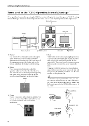
...entry block) to move the pointer by the cursor to indicate that this section will explain the terms that item. Hint As alternative ways to perform this action, you can use a mouse connected to the MOUSE connector of the CS1D. • Cursor The red frame shown in the display.... Cursor Left switch Click Right switch Mouse left or right switch of the track pad (located in the upper center of terms, refer to "CS1D Operating Manual (Basic Operation)." [CURSOR] switches Display Track pad Data entry block [ENTER] switches Left switch Right switch • Display This refers ...
...entry block) to move the pointer by the cursor to indicate that this section will explain the terms that item. Hint As alternative ways to perform this action, you can use a mouse connected to the MOUSE connector of the CS1D. • Cursor The red frame shown in the display.... Cursor Left switch Click Right switch Mouse left or right switch of the track pad (located in the upper center of terms, refer to "CS1D Operating Manual (Basic Operation)." [CURSOR] switches Display Track pad Data entry block [ENTER] switches Left switch Right switch • Display This refers ...
Owner's Manual
Page 23
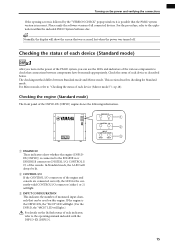
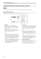
...}. 15 If the engine is the DSP1D-EX, the "96CH" LED will light. {For the DSP1D, the "48CH" LED will light. 3 INPUT CONFIGURATION This indicates the number of monaural input channels that was accessed last when the power was turned off. For the procedure, refer to check that the PM1D..., the LED for Standard mode. Checking the engine (Standard mode) The front panel of all connected devices. Turning on the lit/dark status of each indicator, refer to "Checking the status of each device (Mirror mode)" (→p.18). Please unify the software version of the DSP1D-EX {DSP1D} engine shows...
...}. 15 If the engine is the DSP1D-EX, the "96CH" LED will light. {For the DSP1D, the "48CH" LED will light. 3 INPUT CONFIGURATION This indicates the number of monaural input channels that was accessed last when the power was turned off. For the procedure, refer to check that the PM1D..., the LED for Standard mode. Checking the engine (Standard mode) The front panel of all connected devices. Turning on the lit/dark status of each indicator, refer to "Checking the status of each device (Mirror mode)" (→p.18). Please unify the software version of the DSP1D-EX {DSP1D} engine shows...
Owner's Manual
Page 24
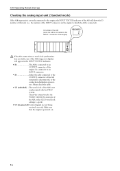
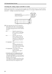
...connection destination is connected to an OUTPUT connector of the engine. Check the connection for the WORD CLOCK IN connector of the AI8, or the CS1D word clock settings (→p.24). • UC (unconnected) Control signals are faulty, one of the following error displays will show the ID number... PHANTOM MASTER ON +48V OFF POWER ON/ OFF ANALOG INPUT BOX If the AI8 connections or word clock synchronization are not being received correctly. CS1D Operating Manual (Start-up) Checking the analog input unit (Standard mode) If the AI8 input unit is correctly connected to the engine, the INPUT...
...connection destination is connected to an OUTPUT connector of the engine. Check the connection for the WORD CLOCK IN connector of the AI8, or the CS1D word clock settings (→p.24). • UC (unconnected) Control signals are faulty, one of the following error displays will show the ID number... PHANTOM MASTER ON +48V OFF POWER ON/ OFF ANALOG INPUT BOX If the AI8 connections or word clock synchronization are not being received correctly. CS1D Operating Manual (Start-up) Checking the analog input unit (Standard mode) If the AI8 input unit is correctly connected to the engine, the INPUT...
Owner's Manual
Page 25
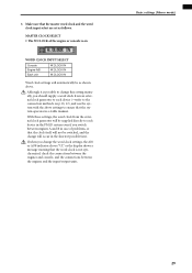
... unit is correctly connected to the engine, the OUTPUT UNIT ID indicator of the AO8 will display the ID number of that unit (i.e.,... 5-8 1-4 POWER ON/ OFF For details on the lit/dark status of the indicators of the DIO8 is connected to the owner's manuals included with the PM1D system....the engine to transmit and receive control signals will appear in the OUTPUT UNIT ID indicator. • E2 The AO8 is connected). INPUT SELECTOR A B POWER ON/ OFF...OUTPUT 3 connector of the engine) I/O UNIT ID I /O UNIT ID indicator of the DIO8 will show the ID number of the following error numbers will...
... unit is correctly connected to the engine, the OUTPUT UNIT ID indicator of the AO8 will display the ID number of that unit (i.e.,... 5-8 1-4 POWER ON/ OFF For details on the lit/dark status of the indicators of the DIO8 is connected to the owner's manuals included with the PM1D system....the engine to transmit and receive control signals will appear in the OUTPUT UNIT ID indicator. • E2 The AO8 is connected). INPUT SELECTOR A B POWER ON/ OFF...OUTPUT 3 connector of the engine) I/O UNIT ID I /O UNIT ID indicator of the DIO8 will show the ID number of the following error numbers will...
Owner's Manual
Page 26
...-EX {DSP1D} is in Mirror mode. Check the connections between engines A/B and the console, and between the DSP1D-EX {DSP1D} and the CS1D. 3 INPUT CONFIGURATION This indicates the number of monaural input channels that can be given priority. The "96CH" LED will light for the DSP1D-EX, and the "48CH" ...LED will light to indicate which of the two sets of CONTROL I /O connectors of the engine and console are not being passed between the engine and the console. CS1D Operating Manual (Start-up) Checking the status of each device (Mirror mode) DSPx2...
...-EX {DSP1D} is in Mirror mode. Check the connections between engines A/B and the console, and between the DSP1D-EX {DSP1D} and the CS1D. 3 INPUT CONFIGURATION This indicates the number of monaural input channels that can be given priority. The "96CH" LED will light for the DSP1D-EX, and the "48CH" ...LED will light to indicate which of the two sets of CONTROL I /O connectors of the engine and console are not being passed between the engine and the console. CS1D Operating Manual (Start-up) Checking the status of each device (Mirror mode) DSPx2...

Owner's Manual
Page 27
...dot ( . ) will show the ID number of that the engine is powered-on. • ID number and A (or b) displayed alternately Since control signals from the CS1D forcibly switched the valid engine to the INPUT 1 connector of the engine) INPUT UNIT ID 1 2 3 4 5 6 7 8 INPUT UNIT NO. However as necessary, ...• UC (unconnected)..Control signals are not correct, one of the following error displays will appear in Mirror mode, the INPUT UNIT ID indicator of the AI8 will light on both sides of the ID number. Re-connect it to an INPUT connector. • E3 The cable connected...
...dot ( . ) will show the ID number of that the engine is powered-on. • ID number and A (or b) displayed alternately Since control signals from the CS1D forcibly switched the valid engine to the INPUT 1 connector of the engine) INPUT UNIT ID 1 2 3 4 5 6 7 8 INPUT UNIT NO. However as necessary, ...• UC (unconnected)..Control signals are not correct, one of the following error displays will appear in Mirror mode, the INPUT UNIT ID indicator of the AI8 will light on both sides of the ID number. Re-connect it to an INPUT connector. • E3 The cable connected...
Owner's Manual
Page 28
...Start-up) Checking the analog output unit (Mirror mode) In Mirror mode if the AO8 is correctly connected to the engine, the OUTPUT UNIT ID indicator of the AO8 will show the ID number of that the engine is not synchronized. Check the cable. • UL (unlocked)....The word clock is... powered-on. • ID number and A (or b) displayed alternately Since control signals from the CS1D forcibly switched the valid engine to A (or B), the setting of the INPUT SELECTOR switch of the AI8 does not match the actual operation. Make sure...
...Start-up) Checking the analog output unit (Mirror mode) In Mirror mode if the AO8 is correctly connected to the engine, the OUTPUT UNIT ID indicator of the AO8 will show the ID number of that the engine is not synchronized. Check the cable. • UL (unlocked)....The word clock is... powered-on. • ID number and A (or b) displayed alternately Since control signals from the CS1D forcibly switched the valid engine to A (or B), the setting of the INPUT SELECTOR switch of the AI8 does not match the actual operation. Make sure...

Owner's Manual
Page 29
... to which the INPUT A connector of the DIO8 is in the 5-8 position, the I/O UNIT ID indicator will show one of the following error displays. • UL (unlocked) ....The word clock of the CS1D. 21 Turning on the power and verifying the connections Checking the digital input/output unit (Mirror mode...) If the output unit and the engine are not correct, the I/O UNIT ID indicator of the DIO8 will show the ID number of that...
... to which the INPUT A connector of the DIO8 is in the 5-8 position, the I/O UNIT ID indicator will show one of the following error displays. • UL (unlocked) ....The word clock of the CS1D. 21 Turning on the power and verifying the connections Checking the digital input/output unit (Mirror mode...) If the output unit and the engine are not correct, the I/O UNIT ID indicator of the DIO8 will show the ID number of that...

Owner's Manual
Page 31
...Hint In the SYSTEM CONNECTION screen you can also check the cabling within the system and the status of the engine. In this setting. This indicates the type of input unit that is connected to each device. If both sets of connectors (1/2) are connected, two lines will show the number ... for the transmitting device in the graphic will be reset. This indicates the type of input unit that the OPERATION MODE field indicates "CONSOLE x1 ENGINE x1." When you perform this time, noise may be displayed instead of the CS1D or AO8 (in particular if an MY8-AT digital I/O card ...
...Hint In the SYSTEM CONNECTION screen you can also check the cabling within the system and the status of the engine. In this setting. This indicates the type of input unit that is connected to each device. If both sets of connectors (1/2) are connected, two lines will show the number ... for the transmitting device in the graphic will be reset. This indicates the type of input unit that the OPERATION MODE field indicates "CONSOLE x1 ENGINE x1." When you perform this time, noise may be displayed instead of the CS1D or AO8 (in particular if an MY8-AT digital I/O card ...

Owner's Manual
Page 33
In Standard mode you change the word clock settings, the AI8 or AO8 indicator shows "UL" or the display shows a message warning that the word clock is not synchronized, check the connections between the engine and console, and the ...connections between the engine and the input/output units. Such a change the word clock settings, noise may be heard from the output jacks of the CS1D and AO8, particularly if an MY8-AT digital I/O card is installed in the word clock settings can occur not only when PM1D system internal settings...
In Standard mode you change the word clock settings, the AI8 or AO8 indicator shows "UL" or the display shows a message warning that the word clock is not synchronized, check the connections between the engine and console, and the ...connections between the engine and the input/output units. Such a change the word clock settings, noise may be heard from the output jacks of the CS1D and AO8, particularly if an MY8-AT digital I/O card is installed in the word clock settings can occur not only when PM1D system internal settings...

Owner's Manual
Page 35
... may be obtained. 27 The OPERATION MODE window will be reset. Click the button marked "CONSOLE x 1 ENGINE x2 (Mirror Mode)." This indicates the type of input unit that is connected to the INPUT connectors and OUTPUT connectors of the engine. At this switch, the word clock will... be displayed instead of the same type are connected, two lines will appear, in the screen. If both jacks (1/2) of the CS1D or AO8 (in the screen. You can also check the cabling within the system and the status of each OUTPUT connector (1-6) of engines A ...
... may be obtained. 27 The OPERATION MODE window will be reset. Click the button marked "CONSOLE x 1 ENGINE x2 (Mirror Mode)." This indicates the type of input unit that is connected to the INPUT connectors and OUTPUT connectors of the engine. At this switch, the word clock will... be displayed instead of the same type are connected, two lines will appear, in the screen. If both jacks (1/2) of the CS1D or AO8 (in the screen. You can also check the cabling within the system and the status of each OUTPUT connector (1-6) of engines A ...
Owner's Manual
Page 37
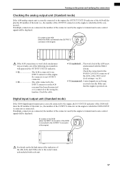
... unit W.CLOCK IN W.CLOCK IN W.CLOCK IN Word clock settings will automatically be switched, and the change the word clock settings, the AI8 or AO8 indicator shows "UL" or the display shows a message warning that the word clock is not synchronized, check the connections between the engines and console, and the...
... unit W.CLOCK IN W.CLOCK IN W.CLOCK IN Word clock settings will automatically be switched, and the change the word clock settings, the AI8 or AO8 indicator shows "UL" or the display shows a message warning that the word clock is not synchronized, check the connections between the engines and console, and the...

Owner's Manual
Page 38
...the console (or to the MONITOR A headphone jack) m Turn on the power in the order of input unit → DSP1D-EX {DSP1D} engine → CS1D console → monitor system m Patch the input unit to an input channel m Press the [CUE] switch of the input channel m Check whether the signal ... you have performed the following actions. • Connect the various components that are part of the PM1D system (→p.6-13) • Use the indicators/LEDs of the PM1D system that the components are correctly connected to the DSP1D-EX {DSP1D} engine. The general procedure is output from the MONITOR...
...the console (or to the MONITOR A headphone jack) m Turn on the power in the order of input unit → DSP1D-EX {DSP1D} engine → CS1D console → monitor system m Patch the input unit to an input channel m Press the [CUE] switch of the input channel m Check whether the signal ... you have performed the following actions. • Connect the various components that are part of the PM1D system (→p.6-13) • Use the indicators/LEDs of the PM1D system that the components are correctly connected to the DSP1D-EX {DSP1D} engine. The general procedure is output from the MONITOR...
Owner's Manual
Page 42
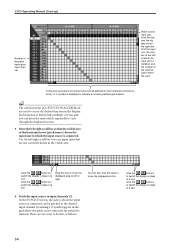
... also click this area to do this box to move the displayed portion. 4. Drag this , as follows. You can press the same switch repeatedly to indicate a currently-patched grid location. There are not currently shown in the display. Move the left /right scroll bar to input channels... 1/2. CS1D Operating Manual (Start-up) Number of the channel (jack) within the card. Hint The switches in steps of a unit. Use the left /right scroll bar ...
... also click this area to do this box to move the displayed portion. 4. Drag this , as follows. You can press the same switch repeatedly to indicate a currently-patched grid location. There are not currently shown in the display. Move the left /right scroll bar to input channels... 1/2. CS1D Operating Manual (Start-up) Number of the channel (jack) within the card. Hint The switches in steps of a unit. Use the left /right scroll bar ...

Owner's Manual
Page 46
... m Connect your monitor system to an output unit m Turn on the power in the order of input unit → DSP1D-EX {DSP1D} engine → CS1D console → monitor system m Patch the input unit to an input channel m Patch the output unit to the STEREO A channel m Send the input channel... appropriate for checking the operation of an output unit connected to verify that are part of the PM1D system (→p.6-13) • Use the indicators/LEDs of an output unit, make sure that the following actions have been completed. • Connect the various components that the components are using ...
... m Connect your monitor system to an output unit m Turn on the power in the order of input unit → DSP1D-EX {DSP1D} engine → CS1D console → monitor system m Patch the input unit to an input channel m Patch the output unit to the STEREO A channel m Send the input channel... appropriate for checking the operation of an output unit connected to verify that are part of the PM1D system (→p.6-13) • Use the indicators/LEDs of an output unit, make sure that the following actions have been completed. • Connect the various components that the components are using ...

Owner's Manual
Page 60
...prototype. DSPx1 Explanatory material that applies only to Mirror mode is used to indicate operating tips or pages to which the PM1D system is used will be aware that uses two engines. • Distinguishing CS1D controllers from the onscreen knobs/buttons Controllers (switches, encoders, volumes) on ...engine is connected to one console, but also the method of the console (CS1D), refer to Standard mode is used ). Screen shots shown in this manual are given in square brackets [ ] to indicate particularly important points, or operations of the 48 channel model are taken from...
...prototype. DSPx1 Explanatory material that applies only to Mirror mode is used to indicate operating tips or pages to which the PM1D system is used will be aware that uses two engines. • Distinguishing CS1D controllers from the onscreen knobs/buttons Controllers (switches, encoders, volumes) on ...engine is connected to one console, but also the method of the console (CS1D), refer to Standard mode is used ). Screen shots shown in this manual are given in square brackets [ ] to indicate particularly important points, or operations of the 48 channel model are taken from...

Owner's Manual
Page 88
... the right of the channel number, a NAME EDIT popup window will appear in which you click the same grid once again, the patch will be indicated by a "●" symbol. (If you can input the name. • NAME EDIT popup window 3. A short name (maximum 4 characters) and a long name (maximum ... axis of the screen shows the patch destination input channel 1-96 (monaural) or the ST IN channel 1-8 (stereo). Input channel name Click this indicates the type and number of input unit/ card slot number/input jack channel number/number of the channel number. To view a portion that jack. ...
... the right of the channel number, a NAME EDIT popup window will appear in which you click the same grid once again, the patch will be indicated by a "●" symbol. (If you can input the name. • NAME EDIT popup window 3. A short name (maximum 4 characters) and a long name (maximum ... axis of the screen shows the patch destination input channel 1-96 (monaural) or the ST IN channel 1-8 (stereo). Input channel name Click this indicates the type and number of input unit/ card slot number/input jack channel number/number of the channel number. To view a portion that jack. ...

Owner's Manual
Page 89
... other channels as input channel patching. [Procedure] 1. LCD FUNCTION ACCESS block OUTPUT [PATCH] switch This is convenient to use the IN PATCH function NAME screen. ("CS1D Reference Manual (Software)" →p.128) Output channel patching Here's how to patch an output unit to access the following screen... Manual (Basic Operation) Hint The short name you can patch the various output channels to the desired output jacks or to the inputs of the CS1D console. 9. Hint If you wish to assign names to numerous channels at once, it is the OUTPUT PATCH screen, in which you assign to each...
... other channels as input channel patching. [Procedure] 1. LCD FUNCTION ACCESS block OUTPUT [PATCH] switch This is convenient to use the IN PATCH function NAME screen. ("CS1D Reference Manual (Software)" →p.128) Output channel patching Here's how to patch an output unit to access the following screen... Manual (Basic Operation) Hint The short name you can patch the various output channels to the desired output jacks or to the inputs of the CS1D console. 9. Hint If you wish to assign names to numerous channels at once, it is the OUTPUT PATCH screen, in which you assign to each...

