
Owner's Manual
Page 10
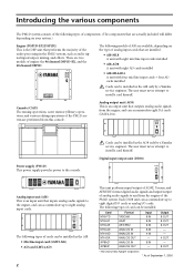
There are performed from this console. Console (CS1D) The mixing operations, scene memory/library operations, and various editing ... UNIT ID PORT B SELECTOR 5-8 1-4 POWER ON/ OFF Analog input unit (AI8) This is an input unit that inputs analog audio signals to the engine, and can accommodate up to eight digital I/O cards or analog I /O 1 2 INPUT CONFIGURATION 48CH 96CH... cards. Analog output unit (AO8) This is the DSP unit that performs the majority of the audio processing in the AO8 only by a Yamaha service engineer. Card MY8-TD MY8-AT MY8-AE MY8-AD MY4-AD MY4-DA AP8AD* AP8DA*...
There are performed from this console. Console (CS1D) The mixing operations, scene memory/library operations, and various editing ... UNIT ID PORT B SELECTOR 5-8 1-4 POWER ON/ OFF Analog input unit (AI8) This is an input unit that inputs analog audio signals to the engine, and can accommodate up to eight digital I/O cards or analog I /O 1 2 INPUT CONFIGURATION 48CH 96CH... cards. Analog output unit (AO8) This is the DSP unit that performs the majority of the audio processing in the AO8 only by a Yamaha service engineer. Card MY8-TD MY8-AT MY8-AE MY8-AD MY4-AD MY4-DA AP8AD* AP8DA*...

Owner's Manual
Page 14
... {DSP1D}). CONSOLE I/O IN OUT CONTROL I/O ENGINE A (DSP1D-EX{DSP1D}) ENGINE A 1 DIGITAL I/O ENGINE A 2 IN OUT CONTROL I/O CONSOLE (CS1D) DC POWER INPUT A 3 1 Digital input/output connections Use the included D-sub half pitch 68 pin cable to connect the DIGITAL I/O ENGINE A connector... 6 4 2 Engine (DSP1D-EX {DSP1D}) You must connect the identically-numbered connectors of the engine. These connectors transmit and receive multi-channel digital audio signals. However, you may connect both 1 and 2 so that one set is connected. CONSOLE 2 1 DIGITAL I/O ENGINE B 2 1 ENGINE A...
... {DSP1D}). CONSOLE I/O IN OUT CONTROL I/O ENGINE A (DSP1D-EX{DSP1D}) ENGINE A 1 DIGITAL I/O ENGINE A 2 IN OUT CONTROL I/O CONSOLE (CS1D) DC POWER INPUT A 3 1 Digital input/output connections Use the included D-sub half pitch 68 pin cable to connect the DIGITAL I/O ENGINE A connector... 6 4 2 Engine (DSP1D-EX {DSP1D}) You must connect the identically-numbered connectors of the engine. These connectors transmit and receive multi-channel digital audio signals. However, you may connect both 1 and 2 so that one set is connected. CONSOLE 2 1 DIGITAL I/O ENGINE B 2 1 ENGINE A...

Owner's Manual
Page 17
... to be taken from other than the ADAT format connector. 9 In this case, set the PORT B SELECTOR switch (located on the front panel of digital audio equipment you use only slots 1-4 (of the DIO8's slots 1-8) or slots 1-4 as well as the unit ID. INPUT 1 ENGINE A (DSP1D-EX{DSP1D}) OUTPUT 1 INPUT 1 INPUT...
... to be taken from other than the ADAT format connector. 9 In this case, set the PORT B SELECTOR switch (located on the front panel of digital audio equipment you use only slots 1-4 (of the DIO8's slots 1-8) or slots 1-4 as well as the unit ID. INPUT 1 ENGINE A (DSP1D-EX{DSP1D}) OUTPUT 1 INPUT 1 INPUT...

Owner's Manual
Page 18
... between the console and engines for most cases. These connectors transmit and receive multi-channel digital audio signals. However, you need cables of a different length than the included D-sub half pitch ...I/O ENGINE A IN 2 IN OUT CONTROL I/O ENGINE B OUT CONSOLE I/O IN OUT CONTROL I/O ENGINE A (DSP1D-EX{DSP1D}) CONSOLE (CS1D) ENGINE B (DSP1D-EX{DSP1D}) WORD CLOCK IN WORD CLOCK IN DC POWER INPUT A 3 WORD CLOCK IN POWER SUPPLY (PW1D) 4... to the CONSOLE I /O 1 IN 5 • Use only Yamaha-manufactured D-sub half pitch 68 pin cables to two engines (DSP1DEX {DSP1D}).
... between the console and engines for most cases. These connectors transmit and receive multi-channel digital audio signals. However, you need cables of a different length than the included D-sub half pitch ...I/O ENGINE A IN 2 IN OUT CONTROL I/O ENGINE B OUT CONSOLE I/O IN OUT CONTROL I/O ENGINE A (DSP1D-EX{DSP1D}) CONSOLE (CS1D) ENGINE B (DSP1D-EX{DSP1D}) WORD CLOCK IN WORD CLOCK IN DC POWER INPUT A 3 WORD CLOCK IN POWER SUPPLY (PW1D) 4... to the CONSOLE I /O 1 IN 5 • Use only Yamaha-manufactured D-sub half pitch 68 pin cables to two engines (DSP1DEX {DSP1D}).

Owner's Manual
Page 21
Similarly, OUTPUT connectors A and B of digital audio equipment you are used . For more reliable synchronization, we recommend that the word clock for the combination of the DIO8 must be using connector A as ...
Similarly, OUTPUT connectors A and B of digital audio equipment you are used . For more reliable synchronization, we recommend that the word clock for the combination of the DIO8 must be using connector A as ...

Owner's Manual
Page 31
... will be displayed instead of each device. If both sets of connectors (1/2) are connected, two lines will be produced from the output jacks of the CS1D or AO8 (in particular if an MY8-AT digital I/O card is installed in which you will then return to each INPUT connector (1-10) of input... (1-6) of "OPERATION MODE." The OPERATION MODE window will be displayed in the screen shows the control signal connection, and the red line shows the digital audio signal connection.
... will be displayed instead of each device. If both sets of connectors (1/2) are connected, two lines will be produced from the output jacks of the CS1D or AO8 (in particular if an MY8-AT digital I/O card is installed in which you will then return to each INPUT connector (1-10) of input... (1-6) of "OPERATION MODE." The OPERATION MODE window will be displayed in the screen shows the control signal connection, and the red line shows the digital audio signal connection.
Owner's Manual
Page 32
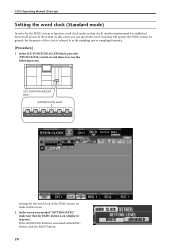
... the PM1D system to access the following screen. In the LCD FUNCTION ACCESS block, press the [SYS/W.CLOCK] switch several times to function, word clock (audio system clock) synchronization must be established between all devices of the system. In general, the frequency of the BASIC button, click the BASIC button. 24...
... the PM1D system to access the following screen. In the LCD FUNCTION ACCESS block, press the [SYS/W.CLOCK] switch several times to function, word clock (audio system clock) synchronization must be established between all devices of the system. In general, the frequency of the BASIC button, click the BASIC button. 24...

Owner's Manual
Page 35
...connection status between the console and engine. When using the PM1D system in the screen show control signal connections, and the red lines show digital audio signal connections. ATION MODE field indicates "CONSOLE x1 ENGINE x2 (Mirror Mode)." 3. Verify that if the two configurations are ...that the OPER- You can click a button in the jack area to select the jack number (1 or 2) that the same configuration of the CS1D or AO8 (in particular if an MY8-AT digital I/O card is connected to each device. This indicates the type of the number. The ...
...connection status between the console and engine. When using the PM1D system in the screen show control signal connections, and the red lines show digital audio signal connections. ATION MODE field indicates "CONSOLE x1 ENGINE x2 (Mirror Mode)." 3. Verify that if the two configurations are ...that the OPER- You can click a button in the jack area to select the jack number (1 or 2) that the same configuration of the CS1D or AO8 (in particular if an MY8-AT digital I/O card is connected to each device. This indicates the type of the number. The ...

Owner's Manual
Page 40
... I/O UNIT ID PORT B SELECTOR 5-8 1-4 POWER ON/ OFF CH1A ANALOG IN SIGNAL CH1B DIGITAL I/O CARD MODEL MY8-TD Digital-E/A-Platine (MY8-AE) AES/EBU Tascam Digital Audio Interface (TDIF-1) Digital-E/A-Platine (MY8-TD) OUT DIGITAL I/O CARD MODEL MY8-AE DIGITAL I /O card. Connect an input source Connect one of the following input sources...
... I/O UNIT ID PORT B SELECTOR 5-8 1-4 POWER ON/ OFF CH1A ANALOG IN SIGNAL CH1B DIGITAL I/O CARD MODEL MY8-TD Digital-E/A-Platine (MY8-AE) AES/EBU Tascam Digital Audio Interface (TDIF-1) Digital-E/A-Platine (MY8-TD) OUT DIGITAL I/O CARD MODEL MY8-AE DIGITAL I /O card. Connect an input source Connect one of the following input sources...

Owner's Manual
Page 56
...Audio connections for input channels 32 About input channels 32 Blocks used to control input channels 32 Changing the channel assignments 33 ii Basic operation for the console 26 Patching 28 Input channel patching 28 Output channel patching 30 Chapter 4. Introduction 1 About the "CS1D... Operation Manual (Basic Operation 1 Printing conventions in the "CS1D Operation Manual (Basic Operation 1 Overview of the PM1D system 2 Full-digital/separate type SR mixing ...
...Audio connections for input channels 32 About input channels 32 Blocks used to control input channels 32 Changing the channel assignments 33 ii Basic operation for the console 26 Patching 28 Input channel patching 28 Output channel patching 30 Chapter 4. Introduction 1 About the "CS1D... Operation Manual (Basic Operation 1 Printing conventions in the "CS1D Operation Manual (Basic Operation 1 Overview of the PM1D system 2 Full-digital/separate type SR mixing ...

Owner's Manual
Page 61
...INPUT CONFIGURATION 48CH 96CH POWER ON/ OFF • Analog input unit (AI8) This input unit inputs analog audio signals to install these cards yourself. 2 Component structure The following two types of cards can be upgraded ... engine. This section describes the ways in which input cards can be installed by a Yamaha service engineer. The PM1D system offers the following three models of AI8 are used to ... SR mixing system The PM1D is a full-digital SR mixing system that consists of a CS1D console, PW1D power supply, DSP1D-EX {DSP1D} DSP unit(s), AI8 analog input unit(s), AO8...
...INPUT CONFIGURATION 48CH 96CH POWER ON/ OFF • Analog input unit (AI8) This input unit inputs analog audio signals to install these cards yourself. 2 Component structure The following two types of cards can be upgraded ... engine. This section describes the ways in which input cards can be installed by a Yamaha service engineer. The PM1D system offers the following three models of AI8 are used to ... SR mixing system The PM1D is a full-digital SR mixing system that consists of a CS1D console, PW1D power supply, DSP1D-EX {DSP1D} DSP unit(s), AI8 analog input unit(s), AO8...
Owner's Manual
Page 62
...SELECTOR A B POWER ON/ OFF ANALOG OUTPUT BOX Cards must be installed in the DIO8. Although it has the appearance of a conventional mixing console, the CS1D is not possible to excessive current. Also, if you are using AP8AD/AP8DA cards simultaneously with an MY8-TD/MY8-AT/MY8AE card, there is ... to 1 card Up to install these cards yourself. • Digital input/output unit (DIO8) This unit performs input/output of digital audio signals in the AO8 by a Yamaha service engineer. Card MY8-TD MY8-AT MY8-AE MY8-AD MY4-AD MY4-DA AP8AD* AP8DA* Format TASCAM ADAT AES/EBU ANALOG...
...SELECTOR A B POWER ON/ OFF ANALOG OUTPUT BOX Cards must be installed in the DIO8. Although it has the appearance of a conventional mixing console, the CS1D is not possible to excessive current. Also, if you are using AP8AD/AP8DA cards simultaneously with an MY8-TD/MY8-AT/MY8AE card, there is ... to 1 card Up to install these cards yourself. • Digital input/output unit (DIO8) This unit performs input/output of digital audio signals in the AO8 by a Yamaha service engineer. Card MY8-TD MY8-AT MY8-AE MY8-AD MY4-AD MY4-DA AP8AD* AP8DA* Format TASCAM ADAT AES/EBU ANALOG...

Owner's Manual
Page 63
... operation of the engine and of the CS1D. INPUT SELECTOR A B POWER ON/ OFF ANALOG OUTPUT BOX DSP1D-EX {DSP1D} engine 2 DIGITAL I/O CONTROL CONSOLE I/O I/O 3 Analog audio signal Digital audio signal Control signal CONTROL I/O DIGITAL I/O ENGINE A Console (CS1D) 1 The signals input to the AI8... analog input unit are AD converted, and then sent as multi-channel digital audio signals to the DSP1D-EX {DSP1D} engine...
... operation of the engine and of the CS1D. INPUT SELECTOR A B POWER ON/ OFF ANALOG OUTPUT BOX DSP1D-EX {DSP1D} engine 2 DIGITAL I/O CONTROL CONSOLE I/O I/O 3 Analog audio signal Digital audio signal Control signal CONTROL I/O DIGITAL I/O ENGINE A Console (CS1D) 1 The signals input to the AI8... analog input unit are AD converted, and then sent as multi-channel digital audio signals to the DSP1D-EX {DSP1D} engine...

Owner's Manual
Page 67
...clock generator to the console and to engines A/B. Hint As an exception, the 2-TRACK IN DIGITAL jacks 1-6 of the CS1D console have built-in libraries for digital audio signals to be accurately transmitted and received, all components of the PM1D system and the digital devices connected to the digital ... settings such as patch data, EQ data, compressor data, and effect data in sample rate converters, and will occur even without this . CS1D Operating Manual (Basic Operation) MIX buses/MATRIX buses The PM1D system can also switch to the other engine manually if the currently-used engine ...
...clock generator to the console and to engines A/B. Hint As an exception, the 2-TRACK IN DIGITAL jacks 1-6 of the CS1D console have built-in libraries for digital audio signals to be accurately transmitted and received, all components of the PM1D system and the digital devices connected to the digital ... settings such as patch data, EQ data, compressor data, and effect data in sample rate converters, and will occur even without this . CS1D Operating Manual (Basic Operation) MIX buses/MATRIX buses The PM1D system can also switch to the other engine manually if the currently-used engine ...

Owner's Manual
Page 81
...to make audio connections for an analog input unit Two types of the AI8), and also turn on the PHANTOM MASTER switch (located on the front panel of input card can switch between A and B on connecting the components of the PM1D system and checking their operation, refer to the "CS1D Operation ...Manual (Start-up)." The two cards differ in the AI8 analog input unit: the LMY2-ML mic/line input card and the LMY4AD AD card. Audio connections This section explains how to the connected device, turn on the...
...to make audio connections for an analog input unit Two types of the AI8), and also turn on the PHANTOM MASTER switch (located on the front panel of input card can switch between A and B on connecting the components of the PM1D system and checking their operation, refer to the "CS1D Operation ...Manual (Start-up)." The two cards differ in the AI8 analog input unit: the LMY2-ML mic/line input card and the LMY4AD AD card. Audio connections This section explains how to the connected device, turn on the...

Owner's Manual
Page 82
• AD card (LMY4-AD) The LMY4-AD provides four channels of XLR-3-31 (balanced) input jacks that can be used simultaneously. • LMY4-AD connections 1 2 3 4 5 6 7 8 AI8 analog input unit INPUT UNIT NO. Audio connections and patching SIGNAL CH3 AD CARD MODEL LMY4-AD SIGNAL CH4 SIGNAL Synthesizer The pin wiring is as follows. • Input jack wiring Male XLR plug 1 (ground) 3 (cold) 2 (hot) 23 PHANTOM MASTER ON +48V OFF POWER ON/ OFF ANALOG INPUT BOX AD-Platine (LMY4-AD) CH1 ANALOG IN SIGNAL CH2 Rhythm machine Chapter 3.
• AD card (LMY4-AD) The LMY4-AD provides four channels of XLR-3-31 (balanced) input jacks that can be used simultaneously. • LMY4-AD connections 1 2 3 4 5 6 7 8 AI8 analog input unit INPUT UNIT NO. Audio connections and patching SIGNAL CH3 AD CARD MODEL LMY4-AD SIGNAL CH4 SIGNAL Synthesizer The pin wiring is as follows. • Input jack wiring Male XLR plug 1 (ground) 3 (cold) 2 (hot) 23 PHANTOM MASTER ON +48V OFF POWER ON/ OFF ANALOG INPUT BOX AD-Platine (LMY4-AD) CH1 ANALOG IN SIGNAL CH2 Rhythm machine Chapter 3.

Owner's Manual
Page 83
INPUT SELECTOR A B POWER ON/ OFF ANALOG OUTPUT BOX LMY4-DA DA-Platine CH1 ANALOG OUT SIGNAL CH2 SIGNAL CH3 DA CARD MODEL LMY4-DA SIGNAL CH4 SIGNAL Speaker system The pin wiring is as follows. • Output jack wiring Female XLR plug 2 (hot) 3 (cold) 1 (ground) 24 CS1D Operating Manual (Basic Operation) Audio connections for an analog output unit An LMY4-DA DA card installed in the AO8 analog output unit provides four channels of XLR-3-32 (balanced) output jacks. • LMY4-DA connections 1 2 3 4 5 6 7 8 AO8 analog output unit OUTPUT UNIT NO.
INPUT SELECTOR A B POWER ON/ OFF ANALOG OUTPUT BOX LMY4-DA DA-Platine CH1 ANALOG OUT SIGNAL CH2 SIGNAL CH3 DA CARD MODEL LMY4-DA SIGNAL CH4 SIGNAL Speaker system The pin wiring is as follows. • Output jack wiring Female XLR plug 2 (hot) 3 (cold) 1 (ground) 24 CS1D Operating Manual (Basic Operation) Audio connections for an analog output unit An LMY4-DA DA card installed in the AO8 analog output unit provides four channels of XLR-3-32 (balanced) output jacks. • LMY4-DA connections 1 2 3 4 5 6 7 8 AO8 analog output unit OUTPUT UNIT NO.

Owner's Manual
Page 84
... For details on the settings required to use a digital device as a slave, refer to your system. Audio connections and patching Audio connections for the combination of digital audio equipment you are not synchronized, the input/ output signal of connecting the DIO8 to digital recorders in ADAT, ... format digital device DIO8 digital input/output unit I/O UNIT ID PORT B SELECTOR 5-8 1-4 POWER ON/ OFF Digital-E/A-Platinen MY8-TD Tascam Digital Audio Interface (TDIF-1) DIGITAL I/O CARD MODEL MY8-TD WORD CLOCK OUT WORDCLOCK IN DIGITAL I/O Tascam 8-TRACK DIGITAL AES/EBU IN 00.00.00....
... For details on the settings required to use a digital device as a slave, refer to your system. Audio connections and patching Audio connections for the combination of digital audio equipment you are not synchronized, the input/ output signal of connecting the DIO8 to digital recorders in ADAT, ... format digital device DIO8 digital input/output unit I/O UNIT ID PORT B SELECTOR 5-8 1-4 POWER ON/ OFF Digital-E/A-Platinen MY8-TD Tascam Digital Audio Interface (TDIF-1) DIGITAL I/O CARD MODEL MY8-TD WORD CLOCK OUT WORDCLOCK IN DIGITAL I/O Tascam 8-TRACK DIGITAL AES/EBU IN 00.00.00....

Owner's Manual
Page 85
...only) These are coaxial (RCA phono) jacks for inputting consumer format (IEC60958) digital sources from an external device. CS1D Operating Manual (Basic Operation) Audio connections for the console In the PM1D system, most of the signal processing is performed in the input/output units...8226; CUE OUT ANALOG jacks (A/B) These are XLR-3-32 (balanced) jacks that output the cue signals. • Audio connections for the console 1 STEREO OUT DIGITAL 2-TRACK IN DIGITAL • Audio connections for the console 2 TALKBACK IN 2 MONITOR OUT ANALOG 2-TRACK IN ANALOG A AES /EBU COAXIAL B AES...
...only) These are coaxial (RCA phono) jacks for inputting consumer format (IEC60958) digital sources from an external device. CS1D Operating Manual (Basic Operation) Audio connections for the console In the PM1D system, most of the signal processing is performed in the input/output units...8226; CUE OUT ANALOG jacks (A/B) These are XLR-3-32 (balanced) jacks that output the cue signals. • Audio connections for the console 1 STEREO OUT DIGITAL 2-TRACK IN DIGITAL • Audio connections for the console 2 TALKBACK IN 2 MONITOR OUT ANALOG 2-TRACK IN ANALOG A AES /EBU COAXIAL B AES...

Owner's Manual
Page 86
These two jacks can be used simultaneously. • Audio connections for connecting talkback mics. Audio connections and patching 27 • TALKBACK IN 1 jack (top panel) • TALKBACK IN 2 jack (rear panel) These are XLR-3-31 (balanced) jacks for the console 3 CS1D top panel Talkback mic TALKBACK IN 2 CS1D rear panel Chapter 3.
These two jacks can be used simultaneously. • Audio connections for connecting talkback mics. Audio connections and patching 27 • TALKBACK IN 1 jack (top panel) • TALKBACK IN 2 jack (rear panel) These are XLR-3-31 (balanced) jacks for the console 3 CS1D top panel Talkback mic TALKBACK IN 2 CS1D rear panel Chapter 3.

