
Owner's Manual
Page 2
...; A SIGNAL indicator and CLIP indicator is provided for purchasing a Yamaha C450/320/160 series power amplifier. This owner's manual covers the three models C450, C320 and C160. Introduction Thank you for each channel. • The PROTECTION indicator shows the status of your plug, proceed as follows: The wire which is coloured GREEN and YELLOW must be connected to the terminal which a mono source is output...
...; A SIGNAL indicator and CLIP indicator is provided for purchasing a Yamaha C450/320/160 series power amplifier. This owner's manual covers the three models C450, C320 and C160. Introduction Thank you for each channel. • The PROTECTION indicator shows the status of your plug, proceed as follows: The wire which is coloured GREEN and YELLOW must be connected to the terminal which a mono source is output...
Owner's Manual
Page 3
... that the power supply voltage specified on the top panel, and a space of the rack cannot be left open .......... 6 Portable Rack Mounting 7 Positioning the Housed Amplifier 7 Specifications 8 General Specifications 8 Block Diagram 9 Dimensions 9 Performance Graphs 10 Troubleshooting 10 Contents Controls and Functions 2 Front Panel 2 Rear Panel 3 Modes: STEREO/PARALLEL/BRIDGE 4 SPEAKER IMPEDANCE 4 Caution for Speaker Connection 5 Rack Mounting 6 Mounting in an EIA standard rack 6 Mounting four or fewer amps in...
... that the power supply voltage specified on the top panel, and a space of the rack cannot be left open .......... 6 Portable Rack Mounting 7 Positioning the Housed Amplifier 7 Specifications 8 General Specifications 8 Block Diagram 9 Dimensions 9 Performance Graphs 10 Troubleshooting 10 Contents Controls and Functions 2 Front Panel 2 Rear Panel 3 Modes: STEREO/PARALLEL/BRIDGE 4 SPEAKER IMPEDANCE 4 Caution for Speaker Connection 5 Rack Mounting 6 Mounting in an EIA standard rack 6 Mounting four or fewer amps in...
Owner's Manual
Page 4
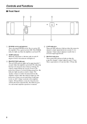
... lights up when the respective channel's output signal exceeds 2 Vrms. This is output. Controls and Functions s Front Panel 2 3 4 TEMP PROTECTION POWER ON OFF 1 A CLIP B SIGNAL 5 1 POWER switch and indicator This is present at the amplifier outputs. clipping). The protection systems are activated when overheating occurs or a DC voltage is the main POWER switch. Output signal clipping is usually due to excessive input signal levels. 5 SIGNAL indicators These green LED indicators light up . Press again to 1/2 watt...
... lights up when the respective channel's output signal exceeds 2 Vrms. This is output. Controls and Functions s Front Panel 2 3 4 TEMP PROTECTION POWER ON OFF 1 A CLIP B SIGNAL 5 1 POWER switch and indicator This is present at the amplifier outputs. clipping). The protection systems are activated when overheating occurs or a DC voltage is the main POWER switch. Output signal clipping is usually due to excessive input signal levels. 5 SIGNAL indicators These green LED indicators light up . Press again to 1/2 watt...
Owner's Manual
Page 5
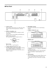
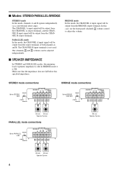
... following diagram. • STEREO, PARALLEL mode SPEAKERS CHANNEL B CHANNEL A BRIDGE STEREO Hot 21 Ground 3 Cold • Barrier strip Hot (+), Cold (-) and Ground (G). 3 STEREO/BRIDGE/PARALLEL switch This slide switch is used . If hum or noise occurs, ground (earth) the unit via this jack, or try connecting it to the chassis of CHANNELS A and B are provided. The minimum impedance for channels A and B are not used to set the amplifier operating mode: STEREO, BRIDGE...
... following diagram. • STEREO, PARALLEL mode SPEAKERS CHANNEL B CHANNEL A BRIDGE STEREO Hot 21 Ground 3 Cold • Barrier strip Hot (+), Cold (-) and Ground (G). 3 STEREO/BRIDGE/PARALLEL switch This slide switch is used . If hum or noise occurs, ground (earth) the unit via this jack, or try connecting it to the chassis of CHANNELS A and B are provided. The minimum impedance for channels A and B are not used to set the amplifier operating mode: STEREO, BRIDGE...
Owner's Manual
Page 6
.... PARALLEL mode In this mode, the CHANNEL A input signal will be output from the CHANNEL B output terminals. STEREO mode connections Set to adjust the volume. Speaker System 4Ω min. 4Ω min. In this mode, the CHANNEL A input signal will be output from the BRIDGE output terminals. Make sure that the impedance does not fall below this mode, channels A and B operate independently (as a conventional stereo amp). BRIDGE mode In this case, use the front panel (channel) A volume control to STEREO BRIDGE SPEAKERS CHANNEL B CHANNEL A BRIDGE STEREO STEREO PARALLEL...
.... PARALLEL mode In this mode, the CHANNEL A input signal will be output from the CHANNEL B output terminals. STEREO mode connections Set to adjust the volume. Speaker System 4Ω min. 4Ω min. In this mode, the CHANNEL A input signal will be output from the BRIDGE output terminals. Make sure that the impedance does not fall below this mode, channels A and B operate independently (as a conventional stereo amp). BRIDGE mode In this case, use the front panel (channel) A volume control to STEREO BRIDGE SPEAKERS CHANNEL B CHANNEL A BRIDGE STEREO STEREO PARALLEL...
Owner's Manual
Page 7
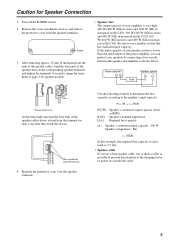
... on the C160. Wire should not touch the chassis. 4. Power amplifier _+ Fuse Speaker system + _ 15mm* * Shown actual size. Use the following formula to determine the fuse capacity according to use as thick a cable as shown below. Be sure to the speaker's input capacity. Caution for speaker porality. • Speaker fuse The output capacity of your amplifier is lower than the rated output of the power amplifier, you use a long speaker cable, use a speaker system that...
... on the C160. Wire should not touch the chassis. 4. Power amplifier _+ Fuse Speaker system + _ 15mm* * Shown actual size. Use the following formula to determine the fuse capacity according to use as thick a cable as shown below. Be sure to the speaker's input capacity. Caution for speaker porality. • Speaker fuse The output capacity of your amplifier is lower than the rated output of the power amplifier, you use a long speaker cable, use a speaker system that...
Owner's Manual
Page 8
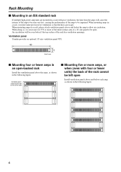
...that the heat can escape. Ventilation panel Yamaha provides an optional 1U-size ventilation panel VP1. 480 44 Unit: mm s Mounting four or fewer amps in an open-backed rack Install the ventilation panel above the amps, as shown in the following figure. When mounting amps in a rack, you must make... has ventilation openings. Ventilation panel (attach to the front or rear of the rack) s Mounting five or more of the entire surface area of a 1U size panel to be open. When mounting amps in a rack, please attach ventilation panels above and below each amp, as shown in the following...
...that the heat can escape. Ventilation panel Yamaha provides an optional 1U-size ventilation panel VP1. 480 44 Unit: mm s Mounting four or fewer amps in an open-backed rack Install the ventilation panel above the amps, as shown in the following figure. When mounting amps in a rack, you must make... has ventilation openings. Ventilation panel (attach to the front or rear of the rack) s Mounting five or more of the entire surface area of a 1U size panel to be open. When mounting amps in a rack, please attach ventilation panels above and below each amp, as shown in the following...
Owner's Manual
Page 9
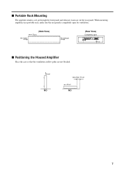
... (Side View) Front Air exhaust (Rear View) Completely open for ventilation. When mounting amplifiers in a portable rack, make sure the rear panel is completely open INPUT CHANNEL B CHANNEL A G G 20 25 15 10 30 6 40 3 ∞ -dB 0 CHANNEL B 20 25 15 10 30 6 40 3 ∞ -dB 0 CHANNEL A (BRIDGE) (PARALLEL) BRIDGE SPEAKERS CHANNEL B CHANNEL A STEREO BRIDGE STEREO PARALLEL s Positioning the Housed Amplifier Place the case so that...
... (Side View) Front Air exhaust (Rear View) Completely open for ventilation. When mounting amplifiers in a portable rack, make sure the rear panel is completely open INPUT CHANNEL B CHANNEL A G G 20 25 15 10 30 6 40 3 ∞ -dB 0 CHANNEL B 20 25 15 10 30 6 40 3 ∞ -dB 0 CHANNEL A (BRIDGE) (PARALLEL) BRIDGE SPEAKERS CHANNEL B CHANNEL A STEREO BRIDGE STEREO PARALLEL s Positioning the Housed Amplifier Place the case so that...
Owner's Manual
Page 10
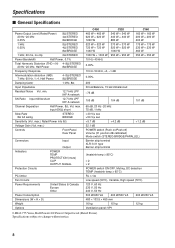
.... 12.7 kHz LPF IHF-A network SN Ratio Input 600Ω shunt 12.7 kHz LPF IHF-A network Channel Separation Half Power, 8Ω, Vol. input 600Ω shunt Slew Rate 8Ω full swing STEREO BRIDGE Sensitivity (Vol. max.) Controls Front Panel Rear Panel Connectors Indicators Protection Circuits Input Output POWER TEMP PROTECTION (mute) CLIP OUTPUT SIGNAL PC limiter Fan Circuits Power Requirements Power Consumption Dimensions (W × H × D) Weight Options United...
.... 12.7 kHz LPF IHF-A network SN Ratio Input 600Ω shunt 12.7 kHz LPF IHF-A network Channel Separation Half Power, 8Ω, Vol. input 600Ω shunt Slew Rate 8Ω full swing STEREO BRIDGE Sensitivity (Vol. max.) Controls Front Panel Rear Panel Connectors Indicators Protection Circuits Input Output POWER TEMP PROTECTION (mute) CLIP OUTPUT SIGNAL PC limiter Fan Circuits Power Requirements Power Consumption Dimensions (W × H × D) Weight Options United...
Owner's Manual
Page 12
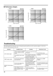
... at a speaker terminal, amplifier terminal, or wire. The PC limiter circuit operates to protect the power transistors. The thermal protection circuit operates to protect the power transistors. Indicator CLIP indicator lights. s Performance Graphs C450 5k Mode:STEREO Both ch Driven RL=4Ω, f=1kHz 1k C320 5k 1k Mode:STEREO Both ch Driven RL=4Ω, f=1kHz Power Consumption [W] Power Consumption [W] 100 20 1 10 100 1k Output Power [W] C160 5k Mode:STEREO Both ch...
... at a speaker terminal, amplifier terminal, or wire. The PC limiter circuit operates to protect the power transistors. The thermal protection circuit operates to protect the power transistors. Indicator CLIP indicator lights. s Performance Graphs C450 5k Mode:STEREO Both ch Driven RL=4Ω, f=1kHz 1k C320 5k 1k Mode:STEREO Both ch Driven RL=4Ω, f=1kHz Power Consumption [W] Power Consumption [W] 100 20 1 10 100 1k Output Power [W] C160 5k Mode:STEREO Both ch...


