
Owner's Manual
Page 1
...be of sufficient magnitude to constitute a risk of important operating and maintenance (servicing) instructions in a safe place for future reference. ENGLISH AX-570/470 Natural Sound Stereo Integrated Amplifier 100W + 100W (8Ω) RMS Output Power, 0.015% THD, 20-20,000 Hz 65W + ... TO RAIN OR MOISTURE. OWNER'S MANUAL CONTENTS Safety Instructions 2 Supplied Accessories 3 Connections 4 Operations 6 Remote Control Transmitter ... 10 Notes about the Remote Control Transmitter 11 Troubleshooting 12 Specifications 13 IMPORTANT! Retain this YAMAHA stereo integrated amplifier.
...be of sufficient magnitude to constitute a risk of important operating and maintenance (servicing) instructions in a safe place for future reference. ENGLISH AX-570/470 Natural Sound Stereo Integrated Amplifier 100W + 100W (8Ω) RMS Output Power, 0.015% THD, 20-20,000 Hz 65W + ... TO RAIN OR MOISTURE. OWNER'S MANUAL CONTENTS Safety Instructions 2 Supplied Accessories 3 Connections 4 Operations 6 Remote Control Transmitter ... 10 Notes about the Remote Control Transmitter 11 Troubleshooting 12 Specifications 13 IMPORTANT! Retain this YAMAHA stereo integrated amplifier.
Owner's Manual
Page 3
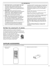
... power outlets that interference will not result in this type of interference, which can not locate the appropriate retailer, please contact Yamaha Electronics Corp., U.S.A. 6660 Orangethorpe Ave, Buena Park, CA 90620. SUPPLIED ACCESSORIES After unpacking, check that the following measures: ..." and "ON", please try to eliminate the problem by Yamaha may cause interference harmful to those products distributed by playing it is 300 ohm ribbon lead, change the lead-in all installation instructions. q Remote Control Transmitter q Batteries (size AA, R6, UM-3) PLAY/CUT...
... power outlets that interference will not result in this type of interference, which can not locate the appropriate retailer, please contact Yamaha Electronics Corp., U.S.A. 6660 Orangethorpe Ave, Buena Park, CA 90620. SUPPLIED ACCESSORIES After unpacking, check that the following measures: ..." and "ON", please try to eliminate the problem by Yamaha may cause interference harmful to those products distributed by playing it is 300 ohm ribbon lead, change the lead-in all installation instructions. q Remote Control Transmitter q Batteries (size AA, R6, UM-3) PLAY/CUT...
Owner's Manual
Page 4
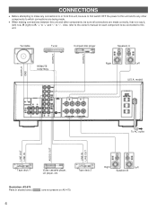
OUTPUT GND OUTPUT OUTPUT Turntable Tuner REMOTE CONTROL Compact disc player Speakers A Right Left (U.S.A. CONNECTIONS q Before attempting to make any connections to or from this unit, be sure to first switch OFF the ... . model) To AC outlet LINE OUT LINE IN AUDIO OUT LINE IN LINE OUT Tape deck 1 Video cassette player, LD player, etc. Tape deck 2 Illustration: AX-570 Parts in shaded area ( ) are being made correctly, that is to say L (left) to L, R (right) to R, "+" to "+" and "-" to "-". Also, refer to the owner's manual...
OUTPUT GND OUTPUT OUTPUT Turntable Tuner REMOTE CONTROL Compact disc player Speakers A Right Left (U.S.A. CONNECTIONS q Before attempting to make any connections to or from this unit, be sure to first switch OFF the ... . model) To AC outlet LINE OUT LINE IN AUDIO OUT LINE IN LINE OUT Tape deck 1 Video cassette player, LD player, etc. Tape deck 2 Illustration: AX-570 Parts in shaded area ( ) are being made correctly, that is to say L (left) to L, R (right) to R, "+" to "+" and "-" to "-". Also, refer to the owner's manual...
Owner's Manual
Page 5
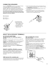
...ground wire of the turntable to either the SPEAKERS A or B terminals. markings are reversed, the sound will lack bass. If you have a YAMAHA turntable with the unit to this unit. To connect such a unit, remove the jumper pins from the speaker wires.] Ž Tighten the knob ...may be used for connection of components) that is, + and - ABOUT THE ACCESSORY TERMINALS AC OUTLETS (SWITCHED) Use these wires are observed. REMOTE CONTROL (PHONO) connector If you connect only one speaker system, connect it to be unnatural and will be connected. For details, refer to the owner...
...ground wire of the turntable to either the SPEAKERS A or B terminals. markings are reversed, the sound will lack bass. If you have a YAMAHA turntable with the unit to this unit. To connect such a unit, remove the jumper pins from the speaker wires.] Ž Tighten the knob ...may be used for connection of components) that is, + and - ABOUT THE ACCESSORY TERMINALS AC OUTLETS (SWITCHED) Use these wires are observed. REMOTE CONTROL (PHONO) connector If you connect only one speaker system, connect it to be unnatural and will be connected. For details, refer to the owner...
Owner's Manual
Page 10
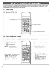
... Other Component Control Identify the remote control transmitter keys with automatic reverse function, pressing DIR A will reverse the direction of tape running. 10 Controls tuner +: Selects higher preset station number. -: Selects lower preset station number. A/B/C/D/E: Selects the page (A - If the CD player, tuner, turntable, equalizer, and tape deck connected to this unit are YAMAHA components...
... Other Component Control Identify the remote control transmitter keys with automatic reverse function, pressing DIR A will reverse the direction of tape running. 10 Controls tuner +: Selects higher preset station number. -: Selects lower preset station number. A/B/C/D/E: Selects the page (A - If the CD player, tuner, turntable, equalizer, and tape deck connected to this unit are YAMAHA components...
Owner's Manual
Page 11
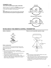
... is half illuminated.) Note The POWER switch on mode STANDBY mode NOTES ABOUT THE REMOTE CONTROL TRANSMITTER Battery installation Remote control transmitter operation range 1 3 Remote control 2 sensor Battery replacement If you find that the remote control transmitter must be turned off when left unused for replacement. POWER on mode STANDBY mode POWER on the front panel of this...
... is half illuminated.) Note The POWER switch on mode STANDBY mode NOTES ABOUT THE REMOTE CONTROL TRANSMITTER Battery installation Remote control transmitter operation range 1 3 Remote control 2 sensor Battery replacement If you find that the remote control transmitter must be turned off when left unused for replacement. POWER on mode STANDBY mode POWER on the front panel of this...
Owner's Manual
Page 12
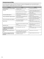
...will reset the protection circuit. Speaker connections are connected in the SYMPTOM column, disconnect the power cord and contact your authorized YAMAHA dealer or service center for help. Incorrect cord connections. REMEDY Firmly plug in the correct phase (+ and -). Connect the...be switched OFF to use those controls. The batteries of the BALANCE control. Using the BASS, TREBLE, BALANCE, LOUDNESS controls and SUBSONIC FILTER switch (AX-570 only) does not affect the tone. Make the GND connection between the turntable and this remote control transmitter are too weak. Only...
...will reset the protection circuit. Speaker connections are connected in the SYMPTOM column, disconnect the power cord and contact your authorized YAMAHA dealer or service center for help. Incorrect cord connections. REMEDY Firmly plug in the correct phase (+ and -). Connect the...be switched OFF to use those controls. The batteries of the BALANCE control. Using the BASS, TREBLE, BALANCE, LOUDNESS controls and SUBSONIC FILTER switch (AX-570 only) does not affect the tone. Make the GND connection between the turntable and this remote control transmitter are too weak. Only...
Owner's Manual
Page 13
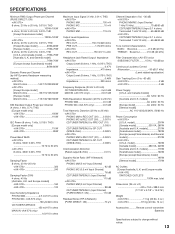
and Canada model] .......75W+75W [Australia, U.K. and General model 70W+70W [Europe (except Scandinavia) model 80W+80W Dynamic Power per Channel (by IHF Dynamic Headroom measuring method) 8/6/4/2 ohms 140/170/220/290W [Except Europe model] 8/6/4/2 ohms 95/115/135/160W [Europe model] 8/6/4/2 ohms 115/135/160/180W DIN Standard Output Power per Channel (PURE DIRECT; SPECIFICATIONS ENGLISH Minimum RMS Output Power per Channel (4 ohms, 1 kHz, 0.7% THD) [Europe model only] ON) 8 ohms, 20 Hz to 20 kHz, 0.015% THD 100W+100W 6 ohms, 20 Hz to 20 kHz, 0.03% THD [Except Scandinavia ...
and Canada model] .......75W+75W [Australia, U.K. and General model 70W+70W [Europe (except Scandinavia) model 80W+80W Dynamic Power per Channel (by IHF Dynamic Headroom measuring method) 8/6/4/2 ohms 140/170/220/290W [Except Europe model] 8/6/4/2 ohms 95/115/135/160W [Europe model] 8/6/4/2 ohms 115/135/160/180W DIN Standard Output Power per Channel (PURE DIRECT; SPECIFICATIONS ENGLISH Minimum RMS Output Power per Channel (4 ohms, 1 kHz, 0.7% THD) [Europe model only] ON) 8 ohms, 20 Hz to 20 kHz, 0.015% THD 100W+100W 6 ohms, 20 Hz to 20 kHz, 0.03% THD [Except Scandinavia ...


