

Owner's Manual
Page 1
.... ENGLISH AX-570/470 Natural Sound Stereo Integrated Amplifier 100W + 100W (8Ω) RMS Output Power, 0.015% THD, 20-20,000 Hz 65W + 65W (8Ω) RMS Output Power, 0.015% THD, 20-20,000 Hz High Dynamic Power, Low Impedance Drive Capability Continuously Variable Loudness Control PURE DIRECT Switch to Reproduce the Purest Source Sound SUBSONIC FILTER Switch to Cut Out Undesirable Ultra-Low-Frequency Signals PRE OUT/MAIN IN Terminals Useful for selecting this YAMAHA stereo integrated amplifier. The...
.... ENGLISH AX-570/470 Natural Sound Stereo Integrated Amplifier 100W + 100W (8Ω) RMS Output Power, 0.015% THD, 20-20,000 Hz 65W + 65W (8Ω) RMS Output Power, 0.015% THD, 20-20,000 Hz High Dynamic Power, Low Impedance Drive Capability Continuously Variable Loudness Control PURE DIRECT Switch to Reproduce the Purest Source Sound SUBSONIC FILTER Switch to Cut Out Undesirable Ultra-Low-Frequency Signals PRE OUT/MAIN IN Terminals Useful for selecting this YAMAHA stereo integrated amplifier. The...
Owner's Manual
Page 2
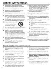
... disconnect the power plug and the cords connecting to rain; Use a clean, dry cloth. 2 7 Always set the volume control to "- ∞" before starting the audio source play: increase the volume gradually to an appropriate level after the play is started. 8 To prevent lightning damage, pull out the power cord and remove the antenna cable during an electrical storm. 9 When not planning to operate normally or exhibits a marked change in a wet...
... disconnect the power plug and the cords connecting to rain; Use a clean, dry cloth. 2 7 Always set the volume control to "- ∞" before starting the audio source play: increase the volume gradually to an appropriate level after the play is started. 8 To prevent lightning damage, pull out the power cord and remove the antenna cable during an electrical storm. 9 When not planning to operate normally or exhibits a marked change in a wet...

Owner's Manual
Page 3
... being affected by Yamaha Corporation of your use this product in FCC Regulations, Part 15 for Class "B" digital devices. Compliance with this manual, meets FCC requirements. q Remote Control Transmitter q Batteries (size AA, R6, UM-3) PLAY/CUT PHONO POWER SKIP PLAY CD SEARCH PAUSE/STOP DISC SKIP - ENGLISH FCC INFORMATION 1. Follow all installations. This equipment generates/uses radio frequencies and, if not installed and used . Utilize power outlets that interference...
... being affected by Yamaha Corporation of your use this product in FCC Regulations, Part 15 for Class "B" digital devices. Compliance with this manual, meets FCC requirements. q Remote Control Transmitter q Batteries (size AA, R6, UM-3) PLAY/CUT PHONO POWER SKIP PLAY CD SEARCH PAUSE/STOP DISC SKIP - ENGLISH FCC INFORMATION 1. Follow all installations. This equipment generates/uses radio frequencies and, if not installed and used . Utilize power outlets that interference...

Owner's Manual
Page 4
... "-" to "-". Also, refer to the owner's manual for each component to be sure all connections are made . model) To AC outlet LINE OUT LINE IN AUDIO OUT LINE IN LINE OUT Tape deck 1 Video cassette player, LD player, etc. OUTPUT GND OUTPUT OUTPUT Turntable Tuner REMOTE CONTROL Compact disc player Speakers A Right Left (U.S.A. CONNECTIONS q Before attempting to make any other components, be connected to this unit and to any connections to or from this unit...
... "-" to "-". Also, refer to the owner's manual for each component to be sure all connections are made . model) To AC outlet LINE OUT LINE IN AUDIO OUT LINE IN LINE OUT Tape deck 1 Video cassette player, LD player, etc. OUTPUT GND OUTPUT OUTPUT Turntable Tuner REMOTE CONTROL Compact disc player Speakers A Right Left (U.S.A. CONNECTIONS q Before attempting to make any other components, be connected to this unit and to any connections to or from this unit...
Owner's Manual
Page 5
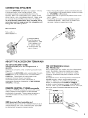
... speakers. These terminals are for overall adjustment of the level of this unit can be connected. If these to connect the power cords from the speakers. Do not let the bare speaker wires touch each other component is 100 watts. Simply insert the Banana Plug connector into the corresponding terminal. These outlets will lack bass. For details, refer to the owner's manual included with the specified impedance...
... speakers. These terminals are for overall adjustment of the level of this unit can be connected. If these to connect the power cords from the speakers. Do not let the bare speaker wires touch each other component is 100 watts. Simply insert the Banana Plug connector into the corresponding terminal. These outlets will lack bass. For details, refer to the owner's manual included with the specified impedance...
Owner's Manual
Page 6
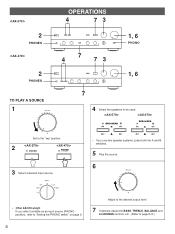
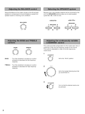
SPEAKERS SPEAKERS ∞ Set to the " " position. 2 POWER POWER /STANDBY 3 Select a desired input source. * If you use two speaker systems, press both the A and B switches. 5 Play the source. 6 * If you select turntable as an input source (PHONO position), refer to "Setting the PHONO switch" on page 9. 6 Adjust to the desired output level. 7 If desired, adjust the BASS, TREBLE, BALANCE and LOUDNESS controls, etc. (Refer to be used. 2 PHONES 2 PHONES TO PLAY A SOURCE 1 OPERATIONS 4 73 4 7 73 1, 6 PHONO 1, 6 7 4 Select the speakers to page 8-9.)
SPEAKERS SPEAKERS ∞ Set to the " " position. 2 POWER POWER /STANDBY 3 Select a desired input source. * If you use two speaker systems, press both the A and B switches. 5 Play the source. 6 * If you select turntable as an input source (PHONO position), refer to "Setting the PHONO switch" on page 9. 6 Adjust to the desired output level. 7 If desired, adjust the BASS, TREBLE, BALANCE and LOUDNESS controls, etc. (Refer to be used. 2 PHONES 2 PHONES TO PLAY A SOURCE 1 OPERATIONS 4 73 4 7 73 1, 6 PHONO 1, 6 7 4 Select the speakers to page 8-9.)
Owner's Manual
Page 7
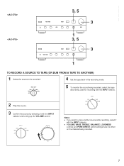
... CD TAPE 1 TUNER TAPE 2 PHONO AUX 5 To monitor the sound being recorded, select the tape deck being recorded. 7 q VOLUME, BASS, TREBLE, BALANCE, LOUDNESS controls and PURE DIRECT switch settings have no effect on the material being used for recording with the INPUT selecto. 2 Play the source. 3 Confirm the source by selecting it with the INPUT selector and turning up the VOLUME control. ENGLISH 3, 5 3 1 3, 5 3 1 TO RECORD A SOURCE TO TAPE (OR DUB FROM A TAPE TO ANOTHER) 1 Select the source to enjoy another source while recording, select it...
... CD TAPE 1 TUNER TAPE 2 PHONO AUX 5 To monitor the sound being recorded, select the tape deck being recorded. 7 q VOLUME, BASS, TREBLE, BALANCE, LOUDNESS controls and PURE DIRECT switch settings have no effect on the material being used for recording with the INPUT selecto. 2 Play the source. 3 Confirm the source by selecting it with the INPUT selector and turning up the VOLUME control. ENGLISH 3, 5 3 1 3, 5 3 1 TO RECORD A SOURCE TO TAPE (OR DUB FROM A TAPE TO ANOTHER) 1 Select the source to enjoy another source while recording, select it...
Owner's Manual
Page 8
... l0 3 9 4 8 5 7 6 Set to the "FLAT" position. 2 Set to the loudest listening level that you to . 3 LOUDNESS l FLAT 2 30 dB l0 3 9 4 8 5 7 6 Turn so that the desired volume can be achieved. 8 SPEAKERS SPEAKERS Adjusting the BASS and TREBLE controls BASS l 0l 2 2 3 3 4 5 4 5 TREBLE l 0l 2 2 3 3 4 5 4 5 BASS : Turn this unit, the SPEAKERS switches allow you would listen to select speaker system A or B, or both at low volume. Adjusting the BALANCE control Adjust the balance of sensitivity to decrease) the high frequency response.
... l0 3 9 4 8 5 7 6 Set to the "FLAT" position. 2 Set to the loudest listening level that you to . 3 LOUDNESS l FLAT 2 30 dB l0 3 9 4 8 5 7 6 Turn so that the desired volume can be achieved. 8 SPEAKERS SPEAKERS Adjusting the BASS and TREBLE controls BASS l 0l 2 2 3 3 4 5 4 5 TREBLE l 0l 2 2 3 3 4 5 4 5 BASS : Turn this unit, the SPEAKERS switches allow you would listen to select speaker system A or B, or both at low volume. Adjusting the BALANCE control Adjust the balance of sensitivity to decrease) the high frequency response.
Owner's Manual
Page 9
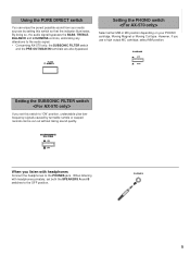
... SPEAKERS A and B switches to the PHONES jack. PHONES 9 By doing so, the audio signal bypasses the BASS, TREBLE, BALANCE and LOUDNESS controls, eliminating any alterations to "ON" position, undesirable ultra-lowfrequency signals caused by setting this switch so that the indicator illuminates. When listening with headphones Connect the headphones to the OFF position. PHONO MC MM Setting the SUBSONIC FILTER switch If you use a high output MC cartridge, select...
... SPEAKERS A and B switches to the PHONES jack. PHONES 9 By doing so, the audio signal bypasses the BASS, TREBLE, BALANCE and LOUDNESS controls, eliminating any alterations to "ON" position, undesirable ultra-lowfrequency signals caused by setting this switch so that the indicator illuminates. When listening with headphones Connect the headphones to the OFF position. PHONO MC MM Setting the SUBSONIC FILTER switch If you use a high output MC cartridge, select...
Owner's Manual
Page 10
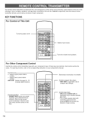
...the remote control transmitter keys with your component's manual. Controls equalizer. * PRESET SKIP selects any preset equalizer curve whenever this is pressed. (After the last preset curve is applicable only to compact disc changer. KEY FUNCTIONS For Control of tape running. 10 A/B/C/D/E: Selects the page (A - E) of the unit. PLAY/CUT PHONO POWER SKIP PLAY CD SEARCH PAUSE/STOP DISC SKIP - PRESET + A/B/C/D/E TUNER DIR A DECK A/B DIR B TAPE 1 PLAY TAPE 2 REC/PAUSE STOP REC MUTE PRESET SKIP ON/FLAT EQ AUX - + VOLUME Selects input source. REMOTE CONTROL TRANSMITTER...
...the remote control transmitter keys with your component's manual. Controls equalizer. * PRESET SKIP selects any preset equalizer curve whenever this is pressed. (After the last preset curve is applicable only to compact disc changer. KEY FUNCTIONS For Control of tape running. 10 A/B/C/D/E: Selects the page (A - E) of the unit. PLAY/CUT PHONO POWER SKIP PLAY CD SEARCH PAUSE/STOP DISC SKIP - PRESET + A/B/C/D/E TUNER DIR A DECK A/B DIR B TAPE 1 PLAY TAPE 2 REC/PAUSE STOP REC MUTE PRESET SKIP ON/FLAT EQ AUX - + VOLUME Selects input source. REMOTE CONTROL TRANSMITTER...

Owner's Manual
Page 11
... avoid direct lighting. 11 ENGLISH STANDBY mode While the power is on, pressing the POWER key on the remote control transmitter switches the unit to work correctly. In this unit should be used for replacement. Replace both batteries with clothing, etc. q Be sure the polarities are weak. POWER on mode STANDBY mode POWER on mode STANDBY mode NOTES ABOUT THE REMOTE CONTROL TRANSMITTER Battery installation Remote control transmitter operation range 1 3 Remote control 2 sensor Battery replacement If you find that the remote control transmitter...
... avoid direct lighting. 11 ENGLISH STANDBY mode While the power is on, pressing the POWER key on the remote control transmitter switches the unit to work correctly. In this unit should be used for replacement. Replace both batteries with clothing, etc. q Be sure the polarities are weak. POWER on mode STANDBY mode POWER on mode STANDBY mode NOTES ABOUT THE REMOTE CONTROL TRANSMITTER Battery installation Remote control transmitter operation range 1 3 Remote control 2 sensor Battery replacement If you find that the remote control transmitter...

Owner's Manual
Page 12
No sound. Sound "hums". Incorrect output cord connections. Incorrect setting of the main unit. wires are connected in the power cord. Select an appropriate input source with new ones. 12 Secure the connections. Sound level is functioning. Using the BASS, TREBLE, BALANCE, LOUDNESS controls and SUBSONIC FILTER switch (AX-570 only) does not affect the tone. The LOUDNESS control is low. The PURE DIRECT switch must be defective. TROUBLESHOOTING If the unit fails to operate normally, check the following points to determine...
No sound. Sound "hums". Incorrect output cord connections. Incorrect setting of the main unit. wires are connected in the power cord. Select an appropriate input source with new ones. 12 Secure the connections. Sound level is functioning. Using the BASS, TREBLE, BALANCE, LOUDNESS controls and SUBSONIC FILTER switch (AX-570 only) does not affect the tone. The LOUDNESS control is low. The PURE DIRECT switch must be defective. TROUBLESHOOTING If the unit fails to operate normally, check the following points to determine...

Owner's Manual
Page 13
...% THD [U.S.A. SPECIFICATIONS ENGLISH Minimum RMS Output Power per Channel (4 ohms, 1 kHz, 0.7% THD) [Europe model only] and Canada model] .......75W+75W [Australia, U.K. and General model 70W+70W [Europe (except Scandinavia) model 80W+80W Dynamic Power per Channel (by IHF Dynamic Headroom measuring method) 8/6/4/2 ohms 140/170/220/290W [Except Europe model] 8/6/4/2 ohms 95/115/135/160W [Europe model] 8/6/4/2 ohms 115/135/160/180W DIN Standard Output Power per Channel (PURE DIRECT;
...% THD [U.S.A. SPECIFICATIONS ENGLISH Minimum RMS Output Power per Channel (4 ohms, 1 kHz, 0.7% THD) [Europe model only] and Canada model] .......75W+75W [Australia, U.K. and General model 70W+70W [Europe (except Scandinavia) model 80W+80W Dynamic Power per Channel (by IHF Dynamic Headroom measuring method) 8/6/4/2 ohms 140/170/220/290W [Except Europe model] 8/6/4/2 ohms 95/115/135/160W [Europe model] 8/6/4/2 ohms 115/135/160/180W DIN Standard Output Power per Channel (PURE DIRECT;


