

Owner's Manual
Page 1
U C A Home Cinema Sound System Système Audio Home Cinéma OWNER'S MANUAL MODE D'EMPLOI STANDBY INPUT 1 INPUT STANDBY/ON PROGRAM INPUT 2 VOLUME L C R REAR D E A B C
U C A Home Cinema Sound System Système Audio Home Cinéma OWNER'S MANUAL MODE D'EMPLOI STANDBY INPUT 1 INPUT STANDBY/ON PROGRAM INPUT 2 VOLUME L C R REAR D E A B C

Owner's Manual
Page 2
The safety and operating instructions should be situated away from power lines. 18 Grounding or Polarization - The unit should be read before the unit is operated. 2 Retain Instructions - Objects have fallen, or liquid has been spilled into and liquids are not likely to be used only with its proper ventilation. All other servicing should be retained for example, near a bathtub, washbowl, kitchen sink, laundry tub, in performance; The unit should be adhered to cords at plugs, convenience receptacles, and the point where they are not spilled into the inside ...
The safety and operating instructions should be situated away from power lines. 18 Grounding or Polarization - The unit should be read before the unit is operated. 2 Retain Instructions - Objects have fallen, or liquid has been spilled into and liquids are not likely to be used only with its proper ventilation. All other servicing should be retained for example, near a bathtub, washbowl, kitchen sink, laundry tub, in performance; The unit should be adhered to cords at plugs, convenience receptacles, and the point where they are not spilled into the inside ...

Owner's Manual
Page 3
... retailer authorized to the operation of product. In the case of interference, which can not locate the appropriate retailer, please contact Yamaha Electronics Corp., U.S.A. 6660 Orangethorpe Ave, Buena Park, CA 90620. If these requirements provides a reasonable level of assurance that interference...equipment by the FCC, to accessories and/or another product use the product. 2. FCC INFORMATION (for US customers only) YAMAHA and the Electronic Industries Association's Consumer Electronics Group want you can be used according to the instructions found to follow instructions ...
... retailer authorized to the operation of product. In the case of interference, which can not locate the appropriate retailer, please contact Yamaha Electronics Corp., U.S.A. 6660 Orangethorpe Ave, Buena Park, CA 90620. If these requirements provides a reasonable level of assurance that interference...equipment by the FCC, to accessories and/or another product use the product. 2. FCC INFORMATION (for US customers only) YAMAHA and the Electronic Industries Association's Consumer Electronics Group want you can be used according to the instructions found to follow instructions ...

Owner's Manual
Page 5
... TO SYANDBY MODE TURNING ON THIS SYSTEM OR SETTING IT TO STANDBY MODE 18 ADJUSTMENTS BEFORE LISTENING OPERATIONS SPEAKER BALANCE ADJUSTMENT 19 Page USING THE AV-S7 USING THE AV-S7 20-22 TROUBLESHOOTING TROUBLESHOOTING 23 SPECIFICATIONS SPECIFICATIONS 24 E-1
... TO SYANDBY MODE TURNING ON THIS SYSTEM OR SETTING IT TO STANDBY MODE 18 ADJUSTMENTS BEFORE LISTENING OPERATIONS SPEAKER BALANCE ADJUSTMENT 19 Page USING THE AV-S7 USING THE AV-S7 20-22 TROUBLESHOOTING TROUBLESHOOTING 23 SPECIFICATIONS SPECIFICATIONS 24 E-1

Owner's Manual
Page 6
...play of sound. s The openings on the surface of the power amplifier/subwoofer unit assure proper ventilation of this system carefully. YAMAHA shall not be held responsible for any accident caused by improper placement or installation of this system with the volume setting at ...Do not plug the AC power plug into the set the volume setting to use excessive force on the switches, controls or connection wires. YAMAHA will rise rapidly. s The sound level at a given volume setting depends on the speaker location and other equipment. s Sudden temperature changes...
...play of sound. s The openings on the surface of the power amplifier/subwoofer unit assure proper ventilation of this system carefully. YAMAHA shall not be held responsible for any accident caused by improper placement or installation of this system with the volume setting at ...Do not plug the AC power plug into the set the volume setting to use excessive force on the switches, controls or connection wires. YAMAHA will rise rapidly. s The sound level at a given volume setting depends on the speaker location and other equipment. s Sudden temperature changes...

Owner's Manual
Page 7
... MODELS ONLY MAIN POWER switch The U.K. This is connected to rain or moisture. To avoid electrical shock, do not expose this to ON switches the AV-S7 system to the terminal which is marked with the coloured markings identifying the terminals in a live socket outlet. Setting this system to the earth terminal...
... MODELS ONLY MAIN POWER switch The U.K. This is connected to rain or moisture. To avoid electrical shock, do not expose this to ON switches the AV-S7 system to the terminal which is marked with the coloured markings identifying the terminals in a live socket outlet. Setting this system to the earth terminal...
Owner's Manual
Page 8
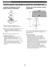
In this case, reposition the center speaker to avoid direct light. • Keep the remote control transmitter away from moisture, excessive heat, shock and vibrations. • The remote control transmitter's range is from 0.2m (8") to strong light (such as shown. Notes concerning use of the remote control transmitter 1 STANDBY INPUT 1 INPUT STANDBY/ON PROGRAM INPUT 2 VOLUME L C R REAR D E A B C 3 2 Within approximately Remote control sensor 6 m (19.7 feet) 1 Remove the battery compartment cover. (Slide the cover in the battery compartment. • Replace all ...
In this case, reposition the center speaker to avoid direct light. • Keep the remote control transmitter away from moisture, excessive heat, shock and vibrations. • The remote control transmitter's range is from 0.2m (8") to strong light (such as shown. Notes concerning use of the remote control transmitter 1 STANDBY INPUT 1 INPUT STANDBY/ON PROGRAM INPUT 2 VOLUME L C R REAR D E A B C 3 2 Within approximately Remote control sensor 6 m (19.7 feet) 1 Remove the battery compartment cover. (Slide the cover in the battery compartment. • Replace all ...

Owner's Manual
Page 9
This system will give you great enjoyment in digital sound field processor (DSP) creates various kinds of Yamaha original digital sound fields simulating an actual concert hall, live house and other venues. When watching a movie source, the builtin Dolby Pro Logic Surround ...a multi-channel audio system which consists of the SW-AVS7, NX-AVS7 and the NX-AV1. English OUTLINE OF THIS SYSTEM SYSTEM CONFIGURATION • The AV-S7 system consists of the units shown below. By driving 6 speakers, the built-in watching TV and playing various audio sources. 6CH POWER AMPLIFIER ACTIVE SERVO...
This system will give you great enjoyment in digital sound field processor (DSP) creates various kinds of Yamaha original digital sound fields simulating an actual concert hall, live house and other venues. When watching a movie source, the builtin Dolby Pro Logic Surround ...a multi-channel audio system which consists of the SW-AVS7, NX-AVS7 and the NX-AV1. English OUTLINE OF THIS SYSTEM SYSTEM CONFIGURATION • The AV-S7 system consists of the units shown below. By driving 6 speakers, the built-in watching TV and playing various audio sources. 6CH POWER AMPLIFIER ACTIVE SERVO...

Owner's Manual
Page 10
... MOVIE) ● Dolby Pro Logic Surround Decoder (Program: DOLBY PRO LOGIC) ● CINEMA DSP: Theater-like Sound Experience by a Combination of Dolby Pro Logic and YAMAHA DSP Technology (Program: DOLBY PRO LOGIC ENHANCED) ● Automatic Input Balance Control for Dolby Pro Logic Surround ● Test Tone Generator for Easier Speaker Balance...
... MOVIE) ● Dolby Pro Logic Surround Decoder (Program: DOLBY PRO LOGIC) ● CINEMA DSP: Theater-like Sound Experience by a Combination of Dolby Pro Logic and YAMAHA DSP Technology (Program: DOLBY PRO LOGIC ENHANCED) ● Automatic Input Balance Control for Dolby Pro Logic Surround ● Test Tone Generator for Easier Speaker Balance...

Owner's Manual
Page 11
... possible to bring you 'll still notice something missing: the acoustic environment of Dolby Pro Logic and YAMAHA DSP technology. Yamaha DSP technology made it in a safe place for Yamaha engineers to present you with its full ability in your room into a wide range of a live ...some TV/cable broadcasts. This unit employs a Dolby Pro Logic Surround decoder similar to the sound of a live concert. CINEMA DSP The YAMAHA "CINEMA DSP" logo indicates these programs are you a whole new world of Dolby Laboratories Licensing Corporation. This system improves the stability of sound...
... possible to bring you 'll still notice something missing: the acoustic environment of Dolby Pro Logic and YAMAHA DSP technology. Yamaha DSP technology made it in a safe place for Yamaha engineers to present you with its full ability in your room into a wide range of a live ...some TV/cable broadcasts. This unit employs a Dolby Pro Logic Surround decoder similar to the sound of a live concert. CINEMA DSP The YAMAHA "CINEMA DSP" logo indicates these programs are you a whole new world of Dolby Laboratories Licensing Corporation. This system improves the stability of sound...

Owner's Manual
Page 12
Position the speakers on the TV picture. Behind your listening position by following the instructions in their proper positions. Precisely between the front speakers. E-8 Nearly six feet (approx. 1.8 m) up from the TV so that there is no influence on the basis of your listening position, facing slightly inward. The rear speakers are not highly directional. SETTING UP THE SPEAKERS SETTING UP THE SPEAKERS Before you make connections, place all , the positioning of the speakers is important because it controls the whole sound quality of this system. Above all units in ...
Position the speakers on the TV picture. Behind your listening position by following the instructions in their proper positions. Precisely between the front speakers. E-8 Nearly six feet (approx. 1.8 m) up from the TV so that there is no influence on the basis of your listening position, facing slightly inward. The rear speakers are not highly directional. SETTING UP THE SPEAKERS SETTING UP THE SPEAKERS Before you make connections, place all , the positioning of the speakers is important because it controls the whole sound quality of this system. Above all units in ...

Owner's Manual
Page 13
In such a case, place the center speaker apart from the TV so that there is no influence on the type of TV or the placement of the center speaker. Notes • Do not place the center speaker on top of a TV whose area is smaller than the bottom area of the center speaker, as necessary E-9 Doing so harms the adhesion strength. • If there is a gap between the center speaker and TV, turn and extend the adjuster on the TV, be careful not to touch the adhesive surface. Affix to the bottom of the center speaker (2 locations) Adjuster Adjust as the center speaker may drop and ...
In such a case, place the center speaker apart from the TV so that there is no influence on the type of TV or the placement of the center speaker. Notes • Do not place the center speaker on top of a TV whose area is smaller than the bottom area of the center speaker, as necessary E-9 Doing so harms the adhesion strength. • If there is a gap between the center speaker and TV, turn and extend the adjuster on the TV, be careful not to touch the adhesive surface. Affix to the bottom of the center speaker (2 locations) Adjuster Adjust as the center speaker may drop and ...

Owner's Manual
Page 14
E-10 To mount speakers on the mounting brackets (type A) 1 Attach the bracket to the bottom of the speaker using the provided screw (type B). 2 2 Turn and/or slide the speaker on the bracket to the desired position, and then tighten the screw. 1 s Mounting the rear speakers Mount the rear speakers on a shelf, rack or put them Mounting directly on the floor, or hang them on the wall. SETTING UP THE SPEAKERS 1 Mounting bracket (type A) Screw 2 (type A) s Mounting the front speakers Place the front speakers on a rack or on a shelf, so that you mount the speakers on the ...
E-10 To mount speakers on the mounting brackets (type A) 1 Attach the bracket to the bottom of the speaker using the provided screw (type B). 2 2 Turn and/or slide the speaker on the bracket to the desired position, and then tighten the screw. 1 s Mounting the rear speakers Mount the rear speakers on a shelf, rack or put them Mounting directly on the floor, or hang them on the wall. SETTING UP THE SPEAKERS 1 Mounting bracket (type A) Screw 2 (type A) s Mounting the front speakers Place the front speakers on a rack or on a shelf, so that you mount the speakers on the ...

Owner's Manual
Page 15
Do not mount them on thin plywood or a soft wall surface material, as the screws may cause them to the wall. ● Select a proper position on the wall to mount the speaker and the bracket so that the screws are provided for each speaker (4). Note Mounting brackets (type C) are held firmly in the holes. WARNING: ● Each speaker weighs 0.7 kg (1 lbs. 9 oz.). E-11 Note If desired, you can hang the speaker on the protruding screws on the wall without using the screw holes on the bracket. s Mounting the speaker on a commercially available speaker stand The provided mounting ...
Do not mount them on thin plywood or a soft wall surface material, as the screws may cause them to the wall. ● Select a proper position on the wall to mount the speaker and the bracket so that the screws are provided for each speaker (4). Note Mounting brackets (type C) are held firmly in the holes. WARNING: ● Each speaker weighs 0.7 kg (1 lbs. 9 oz.). E-11 Note If desired, you can hang the speaker on the protruding screws on the wall without using the screw holes on the bracket. s Mounting the speaker on a commercially available speaker stand The provided mounting ...

Owner's Manual
Page 16
This system requires three connections: system connection, speaker connection and AC supply connection. However, the order of a CD, MD, laser disc player or DVD player. VIDEO AUDIO AUDIO INPUT INPUT OUTPUT L R L R 1 THROUGH 2 INPUT MARK SYSTEM CONNECTOR *1 *2 Audio connection cord (provided) *3 L R 1 THROUGH 2 INPUT MARK SYSTEM CONNECTOR RL FRONT RL FRONT VCR L R VIDEO AUDIO OUTPUT OUTPUT CD or MD player L R AUDIO OUTPUT *1 : Video connection cable (optional) *2,3 : Audio connection cable (optional) E-12 s Making a system connection between the center speaker (...
This system requires three connections: system connection, speaker connection and AC supply connection. However, the order of a CD, MD, laser disc player or DVD player. VIDEO AUDIO AUDIO INPUT INPUT OUTPUT L R L R 1 THROUGH 2 INPUT MARK SYSTEM CONNECTOR *1 *2 Audio connection cord (provided) *3 L R 1 THROUGH 2 INPUT MARK SYSTEM CONNECTOR RL FRONT RL FRONT VCR L R VIDEO AUDIO OUTPUT OUTPUT CD or MD player L R AUDIO OUTPUT *1 : Video connection cable (optional) *2,3 : Audio connection cable (optional) E-12 s Making a system connection between the center speaker (...

Owner's Manual
Page 17
... RL FRONT RL FRONT L R VIDEO AUDIO OUTPUT OUTPUT CD or MD player L R AUDIO OUTPUT *1 : Video connection cable (optional) *2,3 : Audio connection cable (optional) • If the AV-S7 system is set to STANDBY or the turned off, the signal applied to INPUT 1 is sent to the THROUGH terminal of INPUT 1. • Use the... playing back sound from the TV or VCR without using connector cable (optional). * A signal is applied to INPUT 1 at the THROUGH terminals only when the AV-S7 is off. 4 Connect the INPUT 2 terminals (Refer to the AUDIO INPUT terminals on the TV using the...
... RL FRONT RL FRONT L R VIDEO AUDIO OUTPUT OUTPUT CD or MD player L R AUDIO OUTPUT *1 : Video connection cable (optional) *2,3 : Audio connection cable (optional) • If the AV-S7 system is set to STANDBY or the turned off, the signal applied to INPUT 1 is sent to the THROUGH terminal of INPUT 1. • Use the... playing back sound from the TV or VCR without using connector cable (optional). * A signal is applied to INPUT 1 at the THROUGH terminals only when the AV-S7 is off. 4 Connect the INPUT 2 terminals (Refer to the AUDIO INPUT terminals on the TV using the...

Owner's Manual
Page 18
... all connections, plug the AC supply lead into a convenient outlet. • Unplug the AC supply lead from the outlet if this to ON switches the AV-S7 system to be used for a long period of the power amplifier/subwoofer (SW-AVS7) must be set for your local main voltage BEFORE plugging it...
... all connections, plug the AC supply lead into a convenient outlet. • Unplug the AC supply lead from the outlet if this to ON switches the AV-S7 system to be used for a long period of the power amplifier/subwoofer (SW-AVS7) must be set for your local main voltage BEFORE plugging it...

Owner's Manual
Page 19
Normally, use the short cords to connect to the front speakers, and use the long ones to connect to Connect: Connect the provided speaker cords between the SPEAKERS terminals on the power amplifier/subwoofer (SW-AVS7) and the speaker terminals on each other than the provided ones. ● Use the provided speaker cords for your reference. To avoid mistakes, connect the wire with a line to the + terminals on the rear of the speaker wires is correct with no sound will be heard from the speakers. Label On the SW-AVS7: Red: positive (+) Black: negative (-) Œ Ž &#...
Normally, use the short cords to connect to the front speakers, and use the long ones to connect to Connect: Connect the provided speaker cords between the SPEAKERS terminals on the power amplifier/subwoofer (SW-AVS7) and the speaker terminals on each other than the provided ones. ● Use the provided speaker cords for your reference. To avoid mistakes, connect the wire with a line to the + terminals on the rear of the speaker wires is correct with no sound will be heard from the speakers. Label On the SW-AVS7: Red: positive (+) Black: negative (-) Œ Ž &#...
Owner's Manual
Page 20
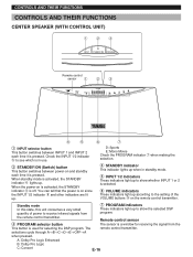
Check the INPUT 1/2 indicator 5 to see which is in standby mode. 5 INPUT 1/2 indicators These indicators light up to receive infrared signals from the This button is off. You can tell that the power is activated, the STANDBY indicator 4 lights up when in use. 2 STANDBY/ON (Switch) button This button switches between INPUT 1 and INPUT 2 each time it is pressed. D: Sports E: Mono Movie Check the PROGRAM indicator 7 when making the selection. 4 STANDBY indicator This indicator lights up . The remote control transmitter. When standby mode is on since the INPUT 1/2 indicator 5 ...
Check the INPUT 1/2 indicator 5 to see which is in standby mode. 5 INPUT 1/2 indicators These indicators light up to receive infrared signals from the This button is off. You can tell that the power is activated, the STANDBY indicator 4 lights up when in use. 2 STANDBY/ON (Switch) button This button switches between INPUT 1 and INPUT 2 each time it is pressed. D: Sports E: Mono Movie Check the PROGRAM indicator 7 when making the selection. 4 STANDBY indicator This indicator lights up . The remote control transmitter. When standby mode is on since the INPUT 1/2 indicator 5 ...

Owner's Manual
Page 21
B: Dolby Pro Logic E-17 C: Concert D: Sports E: Mono Movie Check the PROGRAM indicators 7 of the center speaker when making the selection. 6 CENTER level (+/-) buttons Pressing the "+" button raises and pressing the "-" button lowers the volume level of the center speaker. 7 REAR level (+/-) buttons Pressing the "+" button raises and pressing the "-" button lowers the volume level of the rear speakers. 8 SUBWOOFER level (+/-) buttons Pressing the "+" button raises and pressing the "-" button lowers the volume level of the subwoofer. 5 PROGRAM selector buttons These buttons are used ...
B: Dolby Pro Logic E-17 C: Concert D: Sports E: Mono Movie Check the PROGRAM indicators 7 of the center speaker when making the selection. 6 CENTER level (+/-) buttons Pressing the "+" button raises and pressing the "-" button lowers the volume level of the center speaker. 7 REAR level (+/-) buttons Pressing the "+" button raises and pressing the "-" button lowers the volume level of the rear speakers. 8 SUBWOOFER level (+/-) buttons Pressing the "+" button raises and pressing the "-" button lowers the volume level of the subwoofer. 5 PROGRAM selector buttons These buttons are used ...