Owner's Manual
Page 3
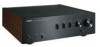
... Monitor Speaker Became of separate components 100th anniversary model AX-2000 Integrated Amplifier High S/N ratio (128 dB), digital direct function equipped AX-2000 GT-CD1 CD Player Top-loading type player with X power supply and X amplifier GT-2000/L Turntable Ultra-precise heavyweight player embodying GT concept CD-1 CD Player First CD Player introduced in 1983 B-6 B-2x Power Amplifier MX-10000 Power Amplifier and CX-10000 Control Amplifier Amplifier that used FETs in Audio...
... Monitor Speaker Became of separate components 100th anniversary model AX-2000 Integrated Amplifier High S/N ratio (128 dB), digital direct function equipped AX-2000 GT-CD1 CD Player Top-loading type player with X power supply and X amplifier GT-2000/L Turntable Ultra-precise heavyweight player embodying GT concept CD-1 CD Player First CD Player introduced in 1983 B-6 B-2x Power Amplifier MX-10000 Power Amplifier and CX-10000 Control Amplifier Amplifier that used FETs in Audio...
Owner's Manual
Page 4
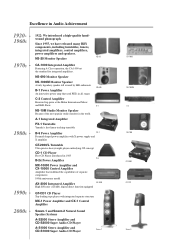
...; The color of the following parts. • Remote control • Batteries (AA, R6, UM-3) (×2) • Power cable • Safety brochure Contents Controls and functions...6 Connections...14 Specifications ...20 Troubleshooting...24 ■ About this unit. 4 En Design and specifications are subject to change in this manual may vary from the original. • Read the "Safety brochure" before using this manual • y indicates a tip for your...
...; The color of the following parts. • Remote control • Batteries (AA, R6, UM-3) (×2) • Power cable • Safety brochure Contents Controls and functions...6 Connections...14 Specifications ...20 Troubleshooting...24 ■ About this unit. 4 En Design and specifications are subject to change in this manual may vary from the original. • Read the "Safety brochure" before using this manual • y indicates a tip for your...
Owner's Manual
Page 6
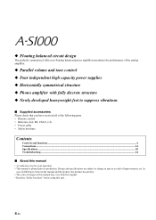
.... Controls and functions ■ Front panel (left side) BASS POWER ON OFF PHONES SPEAKERS OFF A B A+B BI-WIRING - + 1 23 4 1 POWER Press upward or downward to aim the remote control directly at the remote control sensor on the front panel of this unit during operation. 30 30 Within 6 m (20 ft) 6 En y The POWER indicator above lights up when this unit is turned on this unit, there will be a few second delay...
.... Controls and functions ■ Front panel (left side) BASS POWER ON OFF PHONES SPEAKERS OFF A B A+B BI-WIRING - + 1 23 4 1 POWER Press upward or downward to aim the remote control directly at the remote control sensor on the front panel of this unit during operation. 30 30 Within 6 m (20 ft) 6 En y The POWER indicator above lights up when this unit is turned on this unit, there will be a few second delay...
Owner's Manual
Page 7
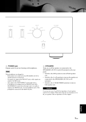
... PHONES jack. Use the headphones jack of 4 Ω or higher. 7 En English Note When headphones are plugged in: - TREBLE - + BALANCE LINE 1 INPUT CD TUNER LINE 2 PHONO MAIN DIRECT L R AUDIO MUTE VOLUME 3 PHONES jack Outputs audio for private listening with an impedance of the preamplifier connected to the MAIN IN jacks. 4 SPEAKERS Turns on or off the speaker set connected to the SPEAKERS L/R CH A and/or B terminals on the rear panel. • Switch to...
... PHONES jack. Use the headphones jack of 4 Ω or higher. 7 En English Note When headphones are plugged in: - TREBLE - + BALANCE LINE 1 INPUT CD TUNER LINE 2 PHONO MAIN DIRECT L R AUDIO MUTE VOLUME 3 PHONES jack Outputs audio for private listening with an impedance of the preamplifier connected to the MAIN IN jacks. 4 SPEAKERS Turns on or off the speaker set connected to the SPEAKERS L/R CH A and/or B terminals on the rear panel. • Switch to...
Owner's Manual
Page 8
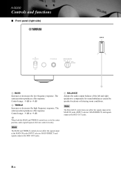
... high frequency response. Controls and functions ■ Front panel (right side) BASS POWER ON OFF PHONES SPEAKERS OFF A B A+B BI-WIRING - + 5 5 BASS Increases or decreases the low frequency response. Note The BALANCE control does not affect the signals input at the MAIN IN jacks (INPUT selector: MAIN DIRECT) and signals output at the REC OUT jacks. 7 BALANCE Adjusts the audio output balance of the left and right speakers to compensate for sound imbalances caused by speaker locations...
... high frequency response. Controls and functions ■ Front panel (right side) BASS POWER ON OFF PHONES SPEAKERS OFF A B A+B BI-WIRING - + 5 5 BASS Increases or decreases the low frequency response. Note The BALANCE control does not affect the signals input at the MAIN IN jacks (INPUT selector: MAIN DIRECT) and signals output at the REC OUT jacks. 7 BALANCE Adjusts the audio output balance of the left and right speakers to compensate for sound imbalances caused by speaker locations...
Owner's Manual
Page 9
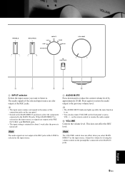
... AUDIO MUTE indicator lights up while the mute function is turned off. Note The audio signals are not output at the REC jacks while LINE2 is selected as the input source. 9 AUDIO MUTE Press downward to the MAIN IN jacks. 9 En English When MAIN DIRECT is selected as the input source. This does not affect the REC level. Adjust the volume level using the volume control on the preamplifier connected to reduce the current volume level by...
... AUDIO MUTE indicator lights up while the mute function is turned off. Note The audio signals are not output at the REC jacks while LINE2 is selected as the input source. 9 AUDIO MUTE Press downward to the MAIN IN jacks. 9 En English When MAIN DIRECT is selected as the input source. This does not affect the REC level. Adjust the volume level using the volume control on the preamplifier connected to reduce the current volume level by...
Owner's Manual
Page 10
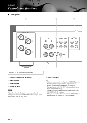
Controls and functions ■ Rear panel 1 2 3 SPEAKERS R CH A B CD R L INPUT TUNER LINE 1 L PHONO R MM MC GND LINE2 PB REC 9 See page 14 for connection information. 1 SPEAKERS L/R CH terminals 2 INPUT jacks 3 LINE2 jacks 4 MAIN IN jacks Note Adjust the volume level using the volume control on the preamplifier connected to the MAIN IN jacks when you select MAIN DIRECT as the input source. 5 PRE OUT jacks y • When you connect audio pin plugs to the PRE OUT jacks to drive the speakers using an...
Controls and functions ■ Rear panel 1 2 3 SPEAKERS R CH A B CD R L INPUT TUNER LINE 1 L PHONO R MM MC GND LINE2 PB REC 9 See page 14 for connection information. 1 SPEAKERS L/R CH terminals 2 INPUT jacks 3 LINE2 jacks 4 MAIN IN jacks Note Adjust the volume level using the volume control on the preamplifier connected to the MAIN IN jacks when you select MAIN DIRECT as the input source. 5 PRE OUT jacks y • When you connect audio pin plugs to the PRE OUT jacks to drive the speakers using an...

Owner's Manual
Page 11
...SPEAKERS L CH A B VOLTAGE SELECTOR 230240V AC IN 6 AC IN Use this inlet to plug in the supplied power cable. 7 VOLTAGE SELECTOR (Asia and General models only) The VOLTAGE SELECTOR on the rear panel of the turntable connected to the PHONO jacks on the rear panel. • Set to the MM position when the connected ...replace the cartridge, be set for your local main voltage BEFORE plugging the power cable into the AC wall outlet. Note When you can adjust the foot height by rotating it. 9 PHONO Selects the type of magnetic cartridge of this unit must be sure to the correct position using...
...SPEAKERS L CH A B VOLTAGE SELECTOR 230240V AC IN 6 AC IN Use this inlet to plug in the supplied power cable. 7 VOLTAGE SELECTOR (Asia and General models only) The VOLTAGE SELECTOR on the rear panel of the turntable connected to the PHONO jacks on the rear panel. • Set to the MM position when the connected ...replace the cartridge, be set for your local main voltage BEFORE plugging the power cable into the AC wall outlet. Note When you can adjust the foot height by rotating it. 9 PHONO Selects the type of magnetic cartridge of this unit must be sure to the correct position using...
Owner's Manual
Page 12
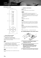
... owner's manual of Yamaha CD player. y You can be controlled by this remote control. 3 Yamaha CD player control buttons Control various functions of your tuner for details. y Press once to pause and twice to resume the audio output. ■ Installing batteries in the remote control 1 1 Infrared signal transmitter Outputs infrared control signals. 2 Yamaha tuner control buttons Control functions of the battery compartment. 3 Slide the cover back until it snaps into the PHONES jack while MAIN DIRECT is selected as the input source, no signals are output...
... owner's manual of Yamaha CD player. y You can be controlled by this remote control. 3 Yamaha CD player control buttons Control various functions of your tuner for details. y Press once to pause and twice to resume the audio output. ■ Installing batteries in the remote control 1 1 Infrared signal transmitter Outputs infrared control signals. 2 Yamaha tuner control buttons Control functions of the battery compartment. 3 Slide the cover back until it snaps into the PHONES jack while MAIN DIRECT is selected as the input source, no signals are output...

Owner's Manual
Page 14
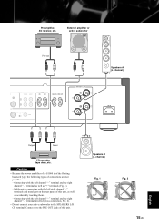
... not let the bare speaker wires touch each speaker must be correct: L (left) to L, R (right) to R, "+" to "+", and "-" to the owner's manual for some turntables. 14 En Also, refer to "-". However, you use speakers with an impedance of your components. • Connect your turntable to the GND terminal to reduce noise in the signal. Connections Speakers A (R channel) CD player Tuner +- SPEAKERS R CH A B CD R L INPUT TUNER LINE 1 L PHONO R MM...
... not let the bare speaker wires touch each speaker must be correct: L (left) to L, R (right) to R, "+" to "+", and "-" to the owner's manual for some turntables. 14 En Also, refer to "-". However, you use speakers with an impedance of your components. • Connect your turntable to the GND terminal to reduce noise in the signal. Connections Speakers A (R channel) CD player Tuner +- SPEAKERS R CH A B CD R L INPUT TUNER LINE 1 L PHONO R MM...
Owner's Manual
Page 15
Caution • Because the power amplifier of A-S1000 is of the floating balanced type, the following types of this unit, as well as "+" terminals (Fig. 1). - Deliberately connecting with the left/right channel "-" terminals and metal part on the rear panel of this unit. + - Speakers B (L channel) Fig. 1 + L - Preamplifier, AV receiver, etc. R + - External amplifier or active subwoofer Pre-out D L INPUT TUNER LINE 1 L R NO MM MC GND LINE2...
Caution • Because the power amplifier of A-S1000 is of the floating balanced type, the following types of this unit, as well as "+" terminals (Fig. 1). - Deliberately connecting with the left/right channel "-" terminals and metal part on the rear panel of this unit. + - Speakers B (L channel) Fig. 1 + L - Preamplifier, AV receiver, etc. R + - External amplifier or active subwoofer Pre-out D L INPUT TUNER LINE 1 L R NO MM MC GND LINE2...

Owner's Manual
Page 17
...-WIRING position. ■ Connecting the power cable Connect the power cable into the AC IN inlet on the rear panel of this unit and create a potential fire hazard. Note When making bi-wiring connections, use the bi-wire connections, switch the SPEAKERS selector to be set of 4 Ω or higher. SPEAKERS L CH A ■ VOLTAGE SELECTOR (Asia and General models only) Caution The VOLTAGE SELECTOR on the rear panel when all connections are connected to...
...-WIRING position. ■ Connecting the power cable Connect the power cable into the AC IN inlet on the rear panel of this unit and create a potential fire hazard. Note When making bi-wiring connections, use the bi-wire connections, switch the SPEAKERS selector to be set of 4 Ω or higher. SPEAKERS L CH A ■ VOLTAGE SELECTOR (Asia and General models only) Caution The VOLTAGE SELECTOR on the rear panel when all connections are connected to...
Owner's Manual
Page 21
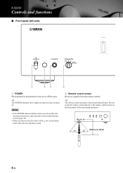
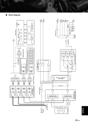
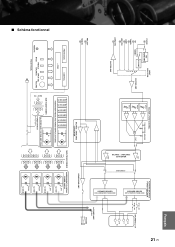
... AMP INPUT SELECTOR CD TUNER LINE1 LINE2 PB MM/MC EQ AMP BUFFER AMP LINE2 REC BUFFER AMP VOLUME & TONE CONTROL ATT. 1 TONE CONTROL DEVICES ATT. 2 ATT. 3 HOT FLAT COLD BALANCE ⇐⇒ UNBALANCE CONVERTER MAIN DIRECT FLOATING BALANCE POWER AMPLIFIER SPEAKER DRIVER HOT (POSITIVE PHASE) SIDE SP A L CH SP B L CH SPEAKERS L CH + A - + B - SPEAKER DRIVER COLD (NEGATIVE PHASE) SIDE PRE OUT MAIN IN PROTECTION CONTROL µ COM REMOTE TREBLE INPUT SEL BASS BALANCE VOLUME FRONT PANEL...
... AMP INPUT SELECTOR CD TUNER LINE1 LINE2 PB MM/MC EQ AMP BUFFER AMP LINE2 REC BUFFER AMP VOLUME & TONE CONTROL ATT. 1 TONE CONTROL DEVICES ATT. 2 ATT. 3 HOT FLAT COLD BALANCE ⇐⇒ UNBALANCE CONVERTER MAIN DIRECT FLOATING BALANCE POWER AMPLIFIER SPEAKER DRIVER HOT (POSITIVE PHASE) SIDE SP A L CH SP B L CH SPEAKERS L CH + A - + B - SPEAKER DRIVER COLD (NEGATIVE PHASE) SIDE PRE OUT MAIN IN PROTECTION CONTROL µ COM REMOTE TREBLE INPUT SEL BASS BALANCE VOLUME FRONT PANEL...
Owner's Manual
Page 24
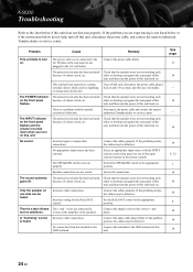
... AC wall outlet. Turn off . There is not set properly. If the problem persists, the cables may be defective. The SPEAKERS switch is a problem with the INPUT selector on the front panel (or one side can be defective. Set the BALANCE control to a strong external electric shock (such as lightning or strong static electricity). reverse at the amplifier or the speakers. A "humming" sound Incorrect cable connections. Connect the audio cable plugs...
... AC wall outlet. Turn off . There is not set properly. If the problem persists, the cables may be defective. The SPEAKERS switch is a problem with the INPUT selector on the front panel (or one side can be defective. Set the BALANCE control to a strong external electric shock (such as lightning or strong static electricity). reverse at the amplifier or the speakers. A "humming" sound Incorrect cable connections. Connect the audio cable plugs...

Owner's Manual
Page 25
Connect the turntable to the jacks other than 30 degrees offaxis from an inverter type of fluorescent lamp, etc.) is low while playing a record. Direct sunlight or lighting (from the front panel. Problem The volume level is striking the remote control sensor of this unit. Turn on the power of this might damage the finish. The remote control functions within a maximum range of this unit When you wipe...
Connect the turntable to the jacks other than 30 degrees offaxis from an inverter type of fluorescent lamp, etc.) is low while playing a record. Direct sunlight or lighting (from the front panel. Problem The volume level is striking the remote control sensor of this unit. Turn on the power of this might damage the finish. The remote control functions within a maximum range of this unit When you wipe...
Owner's Manual
Page 45
SPEAKER DRIVER COLD (NEGATIVE PHASE) SIDE PRE OUT MAIN IN PROTECTION CONTROL µ COM REMOTE TREBLE INPUT SEL BASS BALANCE VOLUME FRONT PANEL for µ COM BALANCE ⇐⇒ UNBALANCE CONVERTER HEADPHONE AMP for MC AMP for EQ AMP for LINE AMP1 for LINE AMP2 for VOLUME1 for VOLUME2 MAIN TRANSFORMER INDEPENDENT FLOATING POWER SUPPLY L CH INDEPENDENT REGULATED POWER SUPPLY (for AUDIO) SUB TRANSFORMER (for POWER AMP / VOLTAGE AMP STAGE...
SPEAKER DRIVER COLD (NEGATIVE PHASE) SIDE PRE OUT MAIN IN PROTECTION CONTROL µ COM REMOTE TREBLE INPUT SEL BASS BALANCE VOLUME FRONT PANEL for µ COM BALANCE ⇐⇒ UNBALANCE CONVERTER HEADPHONE AMP for MC AMP for EQ AMP for LINE AMP1 for LINE AMP2 for VOLUME1 for VOLUME2 MAIN TRANSFORMER INDEPENDENT FLOATING POWER SUPPLY L CH INDEPENDENT REGULATED POWER SUPPLY (for AUDIO) SUB TRANSFORMER (for POWER AMP / VOLTAGE AMP STAGE...
Owner's Manual
Page 52
... of the obsolete outlet. 10 Protect the power cord from loud sounds is often undetectable until it at plugs, convenience receptacles, and the point where they exit from excessive volume levels. Servicing is required when the apparatus has been damaged in the literature accompanying the appliance. Since hearing damage from being walked on the rear of uninsulated "dangerous voltage...
... of the obsolete outlet. 10 Protect the power cord from loud sounds is often undetectable until it at plugs, convenience receptacles, and the point where they exit from excessive volume levels. Servicing is required when the apparatus has been damaged in the literature accompanying the appliance. Since hearing damage from being walked on the rear of uninsulated "dangerous voltage...
Owner's Manual
Page 53
.... This equipment generates/uses radio frequencies and, if not installed and used . In the case of product. Note The plug severed from the mains lead must be destroyed, as follows: The wire which is coloured BLUE must be the source of other electronic devices. ii En Failure to follow instructions could void your FCC authorization to coaxial type cable. If this...
.... This equipment generates/uses radio frequencies and, if not installed and used . In the case of product. Note The plug severed from the mains lead must be destroyed, as follows: The wire which is coloured BLUE must be the source of other electronic devices. ii En Failure to follow instructions could void your FCC authorization to coaxial type cable. If this...
Owner's Manual
Page 54
... in the owner's manual on the back of this unit. 3 Locate this unit away from a wall outlet or the unit during a lightning storm. 14 Do not attempt to modify or fix this unit. Burning objects (i.e. It may overheat, possibly causing damage. 9 Do not use force on this unit must be set for future reference. 2 Install this unit...
... in the owner's manual on the back of this unit. 3 Locate this unit away from a wall outlet or the unit during a lightning storm. 14 Do not attempt to modify or fix this unit. Burning objects (i.e. It may overheat, possibly causing damage. 9 Do not use force on this unit must be set for future reference. 2 Install this unit...
Owner's Manual
Page 55
... of parts due to repair. Limited Guarantee for European Economic Area (EEA) and Switzerland Thank you for any losses or damages, whether direct, consequential or otherwise, save for U.K. resident). Yamaha reserves the right to replace a product with clothing, etc. Periodic maintenance and repair or replacement of extremely low temperatures - Please backup any custom settings or data, as Yamaha may not work...
... of parts due to repair. Limited Guarantee for European Economic Area (EEA) and Switzerland Thank you for any losses or damages, whether direct, consequential or otherwise, save for U.K. resident). Yamaha reserves the right to replace a product with clothing, etc. Periodic maintenance and repair or replacement of extremely low temperatures - Please backup any custom settings or data, as Yamaha may not work...


