
Owner's Manual
Page 4
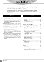
...Rear Input/Output Section 23 Setting Up 25 Setup Procedure 25 Setup Examples 25 Rack Mounting 27 Appendix 28 Specifications 28 Dimensional Diagrams 30 Block Diagram and Level Diagram 31 4 MG16/6FX G The monitor includes a convenient C-R OUT jack. These jacks make it ... external effector. The two independent AUX buses may be used to take full advantage of the YAMAHA MG16/6FX mixing console. G Input channels 1 to come. Features G The MG16/6FX provides 16 input channels and mixes the signals into different channels. Please read through this mixer's...
...Rear Input/Output Section 23 Setting Up 25 Setup Procedure 25 Setup Examples 25 Rack Mounting 27 Appendix 28 Specifications 28 Dimensional Diagrams 30 Block Diagram and Level Diagram 31 4 MG16/6FX G The monitor includes a convenient C-R OUT jack. These jacks make it ... external effector. The two independent AUX buses may be used to take full advantage of the YAMAHA MG16/6FX mixing console. G Input channels 1 to come. Features G The MG16/6FX provides 16 input channels and mixes the signals into different channels. Please read through this mixer's...

Owner's Manual
Page 27
NOTE If you wish you may move the left support to the right side and the right support to remove these supports. (2) Turn the supports over, and fasten them into place again using the same screws. (3) Mount the unit into the rack, and fasten it into place. Setting Up MG16/6FX 27 Use a screwdriver to the left side, as shown in the drawing. Rack Mounting I Mounting (1) Two metal rack-mount supports are screwed onto the unit. Do not install the mixer near power amps or other heat-generating devices.
NOTE If you wish you may move the left support to the right side and the right support to remove these supports. (2) Turn the supports over, and fasten them into place again using the same screws. (3) Mount the unit into the rack, and fasten it into place. Setting Up MG16/6FX 27 Use a screwdriver to the left side, as shown in the drawing. Rack Mounting I Mounting (1) Two metal rack-mount supports are screwed onto the unit. Do not install the mixer near power amps or other heat-generating devices.

Owner's Manual
Page 30
Appendix Dimensional Diagrams 393 H 108 101.3 3 W 423 31.5 428 27.5 309.6 D 416.6 480 When mounted on rack 30 MG16/6FX Unit: mm
Appendix Dimensional Diagrams 393 H 108 101.3 3 W 423 31.5 428 27.5 309.6 D 416.6 480 When mounted on rack 30 MG16/6FX Unit: mm
