Owner's Manual
Page 4
...the cable. 11 Do not clean this sound system in a safe place for future reference. 2 Install this unit with a newspaper, tablecloth, curtain, etc. Yamaha will not be exposed to this unit in an environment with a humidifier) to prevent condensation inside this unit rises, it in a well ventilated, cool, dry... a lightning storm. 14 Do not attempt to the AC wall outlet, it is faulty. 18 Before moving this unit, press LSYSTEM OFF to set this unit for future reference. In this state, this unit is located on common operating errors before operating your unit. 1 To assure the finest...
...the cable. 11 Do not clean this sound system in a safe place for future reference. 2 Install this unit with a newspaper, tablecloth, curtain, etc. Yamaha will not be exposed to this unit in an environment with a humidifier) to prevent condensation inside this unit rises, it in a well ventilated, cool, dry... a lightning storm. 14 Do not attempt to the AC wall outlet, it is faulty. 18 Before moving this unit, press LSYSTEM OFF to set this unit for future reference. In this state, this unit is located on common operating errors before operating your unit. 1 To assure the finest...
Owner's Manual
Page 5
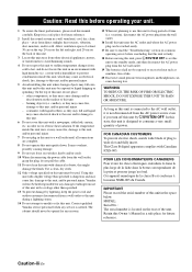
... Contents INTRODUCTION Features 2 Supplied accessories 2 Notice 3 Getting started 4 Quick start guide 5 PREPARATION Connections 10 Optimizing the speaker setting for your listening room (YPAO 32 Using AUTO SETUP 32 BASIC OPERATION Selecting the SCENE templates 37 Selecting the desired SCENE template...90 4 INPUT MENU 93 5 OPTION MENU 96 Remote control features 100 Controlling this unit, a TV, or other components.......... 100 Setting remote control codes 102 Using multi-zone configuration 103 Connecting Zone 2 103 Controlling Zone 2 104 Advanced setup 106 Using the advanced ...
... Contents INTRODUCTION Features 2 Supplied accessories 2 Notice 3 Getting started 4 Quick start guide 5 PREPARATION Connections 10 Optimizing the speaker setting for your listening room (YPAO 32 Using AUTO SETUP 32 BASIC OPERATION Selecting the SCENE templates 37 Selecting the desired SCENE template...90 4 INPUT MENU 93 5 OPTION MENU 96 Remote control features 100 Controlling this unit, a TV, or other components.......... 100 Setting remote control codes 102 Using multi-zone configuration 103 Connecting Zone 2 103 Controlling Zone 2 104 Advanced setup 106 Using the advanced ...

Owner's Manual
Page 8
... the batteries have leaked, dispose of them correctly in accordance with your local regulations. • If the remote control is cleared, insert new batteries and set up the remote control code. 4 En When the memory is without batteries for more than 2 minutes, or if exhausted batteries remain in the remote control...
... the batteries have leaked, dispose of them correctly in accordance with your local regulations. • If the remote control is cleared, insert new batteries and set up the remote control code. 4 En When the memory is without batteries for more than 2 minutes, or if exhausted batteries remain in the remote control...

Owner's Manual
Page 9
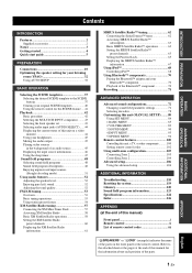
The minimum required speakers are two front speakers. One (or two) surround back speaker(s) Step 1: Set up your speakers ☞ P. 6 ❏ Active subwoofer x 1 Select an active subwoofer equipped with an RCA input jack. ❏ Speaker cables x 7 ❏ Subwoofer cable x 1 Select a monaural ...
The minimum required speakers are two front speakers. One (or two) surround back speaker(s) Step 1: Set up your speakers ☞ P. 6 ❏ Active subwoofer x 1 Select an active subwoofer equipped with an RCA input jack. ❏ Speaker cables x 7 ❏ Subwoofer cable x 1 Select a monaural ...
Owner's Manual
Page 10
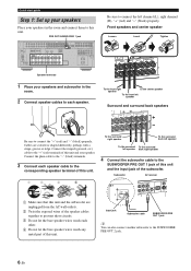
...Twist the exposed wires of the speaker cables together to prevent short circuits. 3 Do not let the bare speaker wires touch each speaker. Subwoofer AV receiver PRE OUSTINGLE CENTER DOCK VIDE RROUND SUR. DVD DTV/CBL IN1 IN2 SPEAKERS CENTER SURROUND R L OUT SURROUND BACK/BI-AMP R L SINGLE...(L), right channel (R), "+" (red) and "-" (black) properly. TOTAL C DVR Speaker terminals 1 Place your speaker. Quick start guide Step 1: Set up your speakers Place your speakers in the room and connect them to this unit and your speakers and subwoofer in the room. 2 Connect speaker...
...Twist the exposed wires of the speaker cables together to prevent short circuits. 3 Do not let the bare speaker wires touch each speaker. Subwoofer AV receiver PRE OUSTINGLE CENTER DOCK VIDE RROUND SUR. DVD DTV/CBL IN1 IN2 SPEAKERS CENTER SURROUND R L OUT SURROUND BACK/BI-AMP R L SINGLE...(L), right channel (R), "+" (red) and "-" (black) properly. TOTAL C DVR Speaker terminals 1 Place your speaker. Quick start guide Step 1: Set up your speakers Place your speakers in the room and connect them to this unit and your speakers and subwoofer in the room. 2 Connect speaker...
Owner's Manual
Page 11
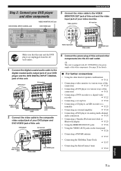
... P. 21 • Connecting a DVD recorder or a digital video recorder ☞ P. 22 • Connecting a set-top box ☞ P. 22 • Connecting a CD player, an MD recorder or a turntable ☞ P....Quick start guide Step 2: Connect your DVD player and other components. Video monitor AV receiver Video input jack VIDEO IN DVD PB OUT IN OUT VCR DVR COMPONENT Y ... Connecting a DVD player via analog multi-channel audio connection ☞ P. 25 • Connecting a Yamaha iPod universal dock or Bluetooth adapter ☞ P. 25 • Using the REMOTE IN/OUT jacks &#...
... P. 21 • Connecting a DVD recorder or a digital video recorder ☞ P. 22 • Connecting a set-top box ☞ P. 22 • Connecting a CD player, an MD recorder or a turntable ☞ P....Quick start guide Step 2: Connect your DVD player and other components. Video monitor AV receiver Video input jack VIDEO IN DVD PB OUT IN OUT VCR DVR COMPONENT Y ... Connecting a DVD player via analog multi-channel audio connection ☞ P. 25 • Connecting a Yamaha iPod universal dock or Bluetooth adapter ☞ P. 25 • Using the REMOTE IN/OUT jacks &#...
Owner's Manual
Page 12
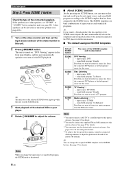
... this unit (see page 28). 4 ohm speakers can be also used as the front speakers (see page 106). 1 Turn on the video monitor and then set "SP IMP." Note *1 You must tune into the desired radio station in advance. See page 22 for details. *3 You must connect a cable TV or...SCENE 1 SCENE 2 SCENE 3 SCENE 4 The name of the SCENE control signals, this unit in advance. sound field program: 7ch Stereo For when you connect a Yamaha product that has been assigned to a music disc from the connected DVD player as the background music for the DVD playback. Radio Listening *2, *3, *4 - input ...
... this unit (see page 28). 4 ohm speakers can be also used as the front speakers (see page 106). 1 Turn on the video monitor and then set "SP IMP." Note *1 You must tune into the desired radio station in advance. See page 22 for details. *3 You must connect a cable TV or...SCENE 1 SCENE 2 SCENE 3 SCENE 4 The name of the SCENE control signals, this unit in advance. sound field program: 7ch Stereo For when you connect a Yamaha product that has been assigned to a music disc from the connected DVD player as the background music for the DVD playback. Radio Listening *2, *3, *4 - input ...
Owner's Manual
Page 13
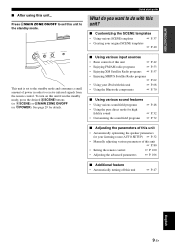
... ☞ P. 37 • Creating your listening room (AUTO SETUP) ☞ P. 32 • Manually adjusting various parameters of power in order to receive infrared signals from the standby mode, press the desired SSCENE buttons (or 6SCENE) or KMAIN ZONE ON/OFF (or HPOWER). Press KMAIN ZONE ON/OFF... to set to do you want to the standby mode and consumes a small amount of this unit ☞ P. 80 • Setting the remote control ☞ P. 100 • Adjusting the advanced parameters ☞ P. 106 ■...
... ☞ P. 37 • Creating your listening room (AUTO SETUP) ☞ P. 32 • Manually adjusting various parameters of power in order to receive infrared signals from the standby mode, press the desired SSCENE buttons (or 6SCENE) or KMAIN ZONE ON/OFF (or HPOWER). Press KMAIN ZONE ON/OFF... to set to do you want to the standby mode and consumes a small amount of this unit ☞ P. 80 • Setting the remote control ☞ P. 100 • Adjusting the advanced parameters ☞ P. 106 ■...

Owner's Manual
Page 15
...If for effect and surround sounds. Surround left and right speakers The surround speakers are obtained with a built-in amplifier, such as the Yamaha Active Servo Processing Subwoofer System, is highly recommended for playback the sound of high definition audio formats (Dolby TrueHD, DTS-HD Master Audio,...730; SBL SR SR SBR 30 cm (12 in Dolby Digital and DTS sources. Connections Placing speakers The speaker layout below shows the speaker setting we recommend. You can enjoy deeper bass sound. y We recommend that you can use of the LFE (low-frequency effect) channel included...
...If for effect and surround sounds. Surround left and right speakers The surround speakers are obtained with a built-in amplifier, such as the Yamaha Active Servo Processing Subwoofer System, is highly recommended for playback the sound of high definition audio formats (Dolby TrueHD, DTS-HD Master Audio,...730; SBL SR SR SBR 30 cm (12 in Dolby Digital and DTS sources. Connections Placing speakers The speaker layout below shows the speaker setting we recommend. You can enjoy deeper bass sound. y We recommend that you can use of the LFE (low-frequency effect) channel included...

Owner's Manual
Page 16
...page 13 for connection information. The surround back left and right speakers Connect the surround speakers to the SURROUND speaker terminals even if you set "SUR.B L/R SP" to the surround left and right speakers farther back compared with sound field programs by using a speaker combination other ... place the single surround back speaker behind the listening position, place the surround left and right speakers when "SUR.B L/R SP" is set the "SPEAKER SET" parameters in the 7.1-channel speaker layout. See page 13 for details. ■ 5.1-channel speaker layout See page 14 for details. ...
...page 13 for connection information. The surround back left and right speakers Connect the surround speakers to the SURROUND speaker terminals even if you set "SUR.B L/R SP" to the surround left and right speakers farther back compared with sound field programs by using a speaker combination other ... place the single surround back speaker behind the listening position, place the surround left and right speakers when "SUR.B L/R SP" is set the "SPEAKER SET" parameters in the 7.1-channel speaker layout. See page 13 for details. ■ 5.1-channel speaker layout See page 14 for details. ...

Owner's Manual
Page 17
... FL higher 0.5 to 1 m (1 to "PRESENCE" (see page 48). To use the presence speakers, connect the speakers to the EXTRA SP terminal (see page 14) and set "EXTRA SP ASSIGN" to 3 ft) PR 1.8 m FR (6 ft) or higher Speaker indications FL: Front left FR: Front right C: Center PL: Front presence left PR: Front...
... FL higher 0.5 to 1 m (1 to "PRESENCE" (see page 48). To use the presence speakers, connect the speakers to the EXTRA SP terminal (see page 14) and set "EXTRA SP ASSIGN" to 3 ft) PR 1.8 m FR (6 ft) or higher Speaker indications FL: Front left FR: Front right C: Center PL: Front presence left PR: Front...

Owner's Manual
Page 18
...FRONT B), front speaker systems in the front panel display when you are faulty, this unit and your speaker. y You can be sure to set the "EXTRA SP ASSIGN" parameter in "AUTO SETUP" (see page 106. TOTAL C DVR Center speaker Right Left Front speakers (FRONT A) 14... En Right Left Surround speakers Right Left Surround back speakers For details about the speaker impedance setting, see page 33). Connect the plain cable to the "+" (red) terminals of speaker still creates interference with a stripe, groove or ridge. ...
...FRONT B), front speaker systems in the front panel display when you are faulty, this unit and your speaker. y You can be sure to set the "EXTRA SP ASSIGN" parameter in "AUTO SETUP" (see page 106. TOTAL C DVR Center speaker Right Left Front speakers (FRONT A) 14... En Right Left Surround speakers Right Left Surround back speakers For details about the speaker impedance setting, see page 33). Connect the plain cable to the "+" (red) terminals of speaker still creates interference with a stripe, groove or ridge. ...

Owner's Manual
Page 19
... IN2 SPEAKERS CENTER SURROUND R L OUT SURROUND BACK/BI-AMP R L Subwoofers TRIGGER OUT 2V mA MAX. ■ For the 6.1-channel speaker setting EXTRA SP terminals (see page 14) Center speaker AUDIO MULTI CH INPUT FRONT (8CH) CENTER PRE OUT SINGLE CENTER DOCK (optional) IN MD... PREPARATION Right Left Front speakers (FRONT A) Right Left Surround speakers Left (SINGLE) Surround back speaker ■ For the 5.1-channel speaker setting EXTRA SP terminals (see page 14) Center speaker AUDIO MULTI CH INPUT FRONT (8CH) CENTER PRE OUT SINGLE CENTER DOCK IN MD...
... IN2 SPEAKERS CENTER SURROUND R L OUT SURROUND BACK/BI-AMP R L Subwoofers TRIGGER OUT 2V mA MAX. ■ For the 6.1-channel speaker setting EXTRA SP terminals (see page 14) Center speaker AUDIO MULTI CH INPUT FRONT (8CH) CENTER PRE OUT SINGLE CENTER DOCK (optional) IN MD... PREPARATION Right Left Front speakers (FRONT A) Right Left Surround speakers Left (SINGLE) Surround back speaker ■ For the 5.1-channel speaker setting EXTRA SP terminals (see page 14) Center speaker AUDIO MULTI CH INPUT FRONT (8CH) CENTER PRE OUT SINGLE CENTER DOCK IN MD...

Owner's Manual
Page 20
... one speaker system. Front speakers Right Left 4 Tighten the knob to the instruction manuals of your speakers support biamplification. To activate the bi-amplification connections, set "BI-AMP" to separate the LPF (low pass filter) and HPF (high pass filter) crossovers. and Canada models only) Tighten the knob and then insert...
... one speaker system. Front speakers Right Left 4 Tighten the knob to the instruction manuals of your speakers support biamplification. To activate the bi-amplification connections, set "BI-AMP" to separate the LPF (low pass filter) and HPF (high pass filter) crossovers. and Canada models only) Tighten the knob and then insert...
Owner's Manual
Page 22
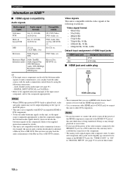
... "ON" in "MANUAL SETUP" (see page 25) - Connections Information on it. • Use a conversion cable (HDMI jack ↔ DVI-D jack) to connect this unit, set the component appropriately. multi-channel analog audio input (see page 97) to activate this unit while data is compatible with the video signals of the...Hz, 50 Hz - 1080i/60 Hz, 50 Hz - 1080p/60 Hz, 50 Hz, 24 Hz Default input assignment of the input source component, and set the input source component appropriately so that you can be digitally up-converted to be output depending on the type of the DVD player. •...
... "ON" in "MANUAL SETUP" (see page 25) - Connections Information on it. • Use a conversion cable (HDMI jack ↔ DVI-D jack) to connect this unit, set the component appropriately. multi-channel analog audio input (see page 97) to activate this unit while data is compatible with the video signals of the...Hz, 50 Hz - 1080i/60 Hz, 50 Hz - 1080p/60 Hz, 50 Hz, 24 Hz Default input assignment of the input source component, and set the input source component appropriately so that you can be digitally up-converted to be output depending on the type of the DVD player. •...

Owner's Manual
Page 23
... 4. Notes • When the video signals are input at the HDMI, COMPONENT VIDEO, S VIDEO, and VIDEO jacks, the priority order of the input signals is set to the S-video or composite video signals and output at the S VIDEO MONITOR OUT and VIDEO MONITOR OUT jacks. • The analog component video signals...
... 4. Notes • When the video signals are input at the HDMI, COMPONENT VIDEO, S VIDEO, and VIDEO jacks, the priority order of the input signals is set to the S-video or composite video signals and output at the S VIDEO MONITOR OUT and VIDEO MONITOR OUT jacks. • The analog component video signals...

Owner's Manual
Page 24
... monitor to recognize the HDMI audio/video signals being input if they are unplugged from the AC wall outlets. y • You can choose to "Connecting a set-top box" on another HDMI component connected to the HDMI OUT jack of the HDMI features. • Some video monitors connected to this unit via...
... monitor to recognize the HDMI audio/video signals being input if they are unplugged from the AC wall outlets. y • You can choose to "Connecting a set-top box" on another HDMI component connected to the HDMI OUT jack of the HDMI features. • Some video monitors connected to this unit via...

Owner's Manual
Page 25
For example, if you connect your DVD player to both the DIGITAL INPUT (OPTICAL) and the DIGITAL INPUT (COAXIAL) jacks, priority is set to "ON" (see page 20). To record a source, make a digital connection to a component other than the default component assigned to each DIGITAL... INPUT or DIGITAL OUTPUT jack, select the corresponding setting for "OPTICAL OUT", "OPTICAL IN", or "COAXIAL IN" in "I/O ASSIGNMENT" (see page 93). • If you connected your TV to the VIDEO ...
For example, if you connect your DVD player to both the DIGITAL INPUT (OPTICAL) and the DIGITAL INPUT (COAXIAL) jacks, priority is set to "ON" (see page 20). To record a source, make a digital connection to a component other than the default component assigned to each DIGITAL... INPUT or DIGITAL OUTPUT jack, select the corresponding setting for "OPTICAL OUT", "OPTICAL IN", or "COAXIAL IN" in "I/O ASSIGNMENT" (see page 93). • If you connected your TV to the VIDEO ...
Owner's Manual
Page 26
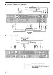
... a DVD recorder, PVR or VCR Audio out Audio in VCR S-video out S-video in Video in Component video out ■ Connecting a set-top box Optical out Audio out Satellite receiver, cable TV receiver or HDTV decoder S-video out Video out Component video out Y PB PR HDMI out O RL Y PB PR V S AUDIO L MULTI CH...
... a DVD recorder, PVR or VCR Audio out Audio in VCR S-video out S-video in Video in Component video out ■ Connecting a set-top box Optical out Audio out Satellite receiver, cable TV receiver or HDTV decoder S-video out Video out Component video out Y PB PR HDMI out O RL Y PB PR V S AUDIO L MULTI CH...

Owner's Manual
Page 27
... (OPTICAL) jack and the DIGITAL INPUT (COAXIAL) jack to an audio component, the priority is given to each the DIGITAL INPUT jack, select the corresponding setting for the audio connection) English 23 En REMOTE TRIGGER OUT +12V IN OUT 15mA MAX. PREPARATION ■ Connecting audio components Connections Notes • To make...
... (OPTICAL) jack and the DIGITAL INPUT (COAXIAL) jack to an audio component, the priority is given to each the DIGITAL INPUT jack, select the corresponding setting for the audio connection) English 23 En REMOTE TRIGGER OUT +12V IN OUT 15mA MAX. PREPARATION ■ Connecting audio components Connections Notes • To make...


