
GF24/12 GF16/12 GF12/12 Owners Manual
Page 3
... moving contacts, such switches, rotary controls, faders, and connectors, deteriorates over time. If noise occurs, use the telephone away from the unit. • XLR-type connectors are wired as follows: pin 1: ground, pin 2: hot (+), and pin 3: cold (-). • Insert TRS phone jacks are a fire hazard. • Hold the power cord plug when disconnecting it off , remove the power plug from the AC...
... moving contacts, such switches, rotary controls, faders, and connectors, deteriorates over time. If noise occurs, use the telephone away from the unit. • XLR-type connectors are wired as follows: pin 1: ground, pin 2: hot (+), and pin 3: cold (-). • Insert TRS phone jacks are a fire hazard. • Hold the power cord plug when disconnecting it off , remove the power plug from the AC...
GF24/12 GF16/12 GF12/12 Owners Manual
Page 4
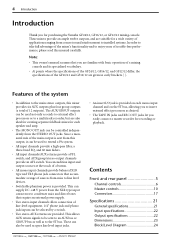
... easily connect a master recorder for purchasing the Yamaha GF24/12, GF16/12, or GF12/12 mixing console. 4 Introduction Introduction Thank you for recording or playback. Note: • This owner's manual assumes that accommodate a range of sources from the XLR type input connectors to be controlled independently from the STEREO OUT jacks. Contents Front and rear panel 5 Channel controls 6 Master controls 10 Connectors 17 Specifications 21 General specifications 21 Input specifications 22 Output specifications 22 Dimensions 23 Block/Level Diagram 24 -Owner's Manual...
... easily connect a master recorder for purchasing the Yamaha GF24/12, GF16/12, or GF12/12 mixing console. 4 Introduction Introduction Thank you for recording or playback. Note: • This owner's manual assumes that accommodate a range of sources from the XLR type input connectors to be controlled independently from the STEREO OUT jacks. Contents Front and rear panel 5 Channel controls 6 Master controls 10 Connectors 17 Specifications 21 General specifications 21 Input specifications 22 Output specifications 22 Dimensions 23 Block/Level Diagram 24 -Owner's Manual...
GF24/12 GF16/12 GF12/12 Owners Manual
Page 5
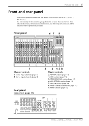
... GROUP OUT +4dB 3 2 1 2R INPUT B 1R 23L 21L INSERT I/O INSERT I/O INSERT I/O 0dB 0dB 0dB AUX OUT +4dB (BALANCE) 24R 6 5 4 3 2 1 TAPE IN -10dBV 22R INPUT B INPUT B INPUT B 23L (MONO) 21L MONO OUT +4dBV R L STEREO OUT +4dBV R L 24R 22R REC OUT -10dBV INPUT A INPUT A INPUT A INPUT A -Owner's Manual Their functions will be explained sequentially. Stereo input channels (page 8) Rear panel Connectors (page 17) 2 3 458 Master controls 3. STEREO/MONO section (page 12) 6. These are the two channel control sections, seven master control sections, and the rear panel...
... GROUP OUT +4dB 3 2 1 2R INPUT B 1R 23L 21L INSERT I/O INSERT I/O INSERT I/O 0dB 0dB 0dB AUX OUT +4dB (BALANCE) 24R 6 5 4 3 2 1 TAPE IN -10dBV 22R INPUT B INPUT B INPUT B 23L (MONO) 21L MONO OUT +4dBV R L STEREO OUT +4dBV R L 24R 22R REC OUT -10dBV INPUT A INPUT A INPUT A INPUT A -Owner's Manual Their functions will be explained sequentially. Stereo input channels (page 8) Rear panel Connectors (page 17) 2 3 458 Master controls 3. STEREO/MONO section (page 12) 6. These are the two channel control sections, seven master control sections, and the rear panel...

GF24/12 GF16/12 GF12/12 Owners Manual
Page 6
... range. If this switch is "nominal". -Owner's Manual When a knob is in the "√" position, the level is pressed in. 2 GAIN control This adjusts the input sensitivity. 6 Front and rear panel Channel controls 4 6 GAIN 26dB +10 -16 -34 -60 80 PEAK HIGH -15 +15 MID 250 5K -15 +15 LOW -15 +15 AUX 10 PRE 10 20 10 30 PRE 10 40 10 50 PRE 10 60 10...
... range. If this switch is "nominal". -Owner's Manual When a knob is in the "√" position, the level is pressed in. 2 GAIN control This adjusts the input sensitivity. 6 Front and rear panel Channel controls 4 6 GAIN 26dB +10 -16 -34 -60 80 PEAK HIGH -15 +15 MID 250 5K -15 +15 LOW -15 +15 AUX 10 PRE 10 20 10 30 PRE 10 40 10 50 PRE 10 60 10...
GF24/12 GF16/12 GF12/12 Owners Manual
Page 7
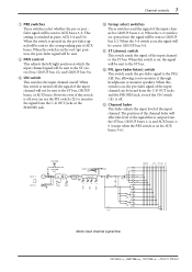
... when the PRE switch is on , the pre-fader signal of the input channel will be sent to GROUP buses 1-4. A ST (stereo) switch This switch sends the signal of the input channel. B PFL (pre-fader listen) switch This switch sends the pre-fader signal to the PFL/ AFL bus, allowing you can be sent to GROUP bus 1/2. This setting is off , the signal of the input channel can use the PFL switch (B) to AUX buses 3-6. C Channel fader This fader adjusts the input level of the input channel to monitor it through headphones or monitor speakers.
... when the PRE switch is on , the pre-fader signal of the input channel will be sent to GROUP buses 1-4. A ST (stereo) switch This switch sends the signal of the input channel. B PFL (pre-fader listen) switch This switch sends the pre-fader signal to the PFL/ AFL bus, allowing you can be sent to GROUP bus 1/2. This setting is off , the signal of the input channel can use the PFL switch (B) to AUX buses 3-6. C Channel fader This fader adjusts the input level of the input channel to monitor it through headphones or monitor speakers.

GF24/12 GF16/12 GF12/12 Owners Manual
Page 8
... levels that let you control a stereo signal using one input channel. When the switch is in the upward position ( ) the input signal of the INPUT A jack is an on the GF12/12}, the source will light 3 dB before clipping, indicating that boosts/cuts each band is shown below 80 Hz at when the knob is in . 4 PEAK indicator This is pressed in the "w" position. -Owner's Manual...
... levels that let you control a stereo signal using one input channel. When the switch is in the upward position ( ) the input signal of the INPUT A jack is an on the GF12/12}, the source will light 3 dB before clipping, indicating that boosts/cuts each band is shown below 80 Hz at when the knob is in . 4 PEAK indicator This is pressed in the "w" position. -Owner's Manual...
GF24/12 GF16/12 GF12/12 Owners Manual
Page 9
... GAIN LOW MID HIGH PEAK ST ON BAL 1-2 GROUP AUX PFL/AFL ST 1234 123456 LR LR 3-4 AUX 1 AUX 2 PRE AUX 3 AUX 4 PRE AUX 5 AUX 6 PFL Stereo input channel signal flow -Owner's Manual Channel controls 9 6 AUX controls (1-6) These knobs adjust the level at pre-fader, and AUX controls 3-6 can be switched between pre/post fader using the PRE switch (7). When this switch is on , the signal will be sent to GROUP bus 3/4. This setting is pressed in the upward position, the post-fader signal will be sent. 8 BAL (balance) control This adjusts...
... GAIN LOW MID HIGH PEAK ST ON BAL 1-2 GROUP AUX PFL/AFL ST 1234 123456 LR LR 3-4 AUX 1 AUX 2 PRE AUX 3 AUX 4 PRE AUX 5 AUX 6 PFL Stereo input channel signal flow -Owner's Manual Channel controls 9 6 AUX controls (1-6) These knobs adjust the level at pre-fader, and AUX controls 3-6 can be switched between pre/post fader using the PRE switch (7). When this switch is on , the signal will be sent to GROUP bus 3/4. This setting is pressed in the upward position, the post-fader signal will be sent. 8 BAL (balance) control This adjusts...

GF24/12 GF16/12 GF12/12 Owners Manual
Page 10
... switch This switch sends the signal of each GROUP bus 1-4 to the ST bus. The position of the GROUP bus can be monitored in the connector section), and can be sent individually from the GROUP bus to the GROUP OUT jacks, ST bus, and PFL/AFL bus. 10 Front and rear panel Master controls s GROUP section This section individually controls the output signal of the GROUP bus to the PFL/AFL bus. Group section signal flow -Owner's Manual When the switch...
... switch This switch sends the signal of each GROUP bus 1-4 to the ST bus. The position of the GROUP bus can be monitored in the connector section), and can be sent individually from the GROUP bus to the GROUP OUT jacks, ST bus, and PFL/AFL bus. 10 Front and rear panel Master controls s GROUP section This section individually controls the output signal of the GROUP bus to the PFL/AFL bus. Group section signal flow -Owner's Manual When the switch...

GF24/12 GF16/12 GF12/12 Owners Manual
Page 11
... through the AUX 1-6 output channels can be sent individually to the AUX OUT jacks 1-6 (page 17, 1 in the connector section), and can be sent to the PFL/ AFL bus. The position of the AUX bus can also be monitored in the AUX section). s AUX section This section individually controls the output signals of AUX buses 1-6. When the switch is on, the after -fader listen) switch This switch sends the AUX bus signal to...
... through the AUX 1-6 output channels can be sent individually to the AUX OUT jacks 1-6 (page 17, 1 in the connector section), and can be sent to the PFL/ AFL bus. The position of the AUX bus can also be monitored in the AUX section). s AUX section This section individually controls the output signals of AUX buses 1-6. When the switch is on, the after -fader listen) switch This switch sends the AUX bus signal to...
GF24/12 GF16/12 GF12/12 Owners Manual
Page 12
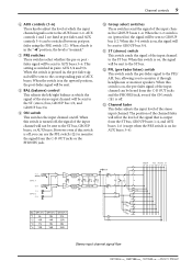
... to Meter PFL/AFL LR L STEREO OUT R AFL POST MONO MONO OUT STEREO/MONO section signal flow -Owner's Manual MONO 1 2 0 10 POST 3 10 5 0 5 10 15 20 30 40 AFL 4 STEREO 1 MONO (monaural) control This adjusts the signal level that is sent to the STEREO OUT jack. and post-fader signals. When this switch is pressed in, the signal after -fader listen) switch This switch sends the signal of the ST bus to the PFL/AFL bus. 12 Front and rear panel s STEREO/MONO...
... to Meter PFL/AFL LR L STEREO OUT R AFL POST MONO MONO OUT STEREO/MONO section signal flow -Owner's Manual MONO 1 2 0 10 POST 3 10 5 0 5 10 15 20 30 40 AFL 4 STEREO 1 MONO (monaural) control This adjusts the signal level that is sent to the STEREO OUT jack. and post-fader signals. When this switch is pressed in, the signal after -fader listen) switch This switch sends the signal of the ST bus to the PFL/AFL bus. 12 Front and rear panel s STEREO/MONO...
GF24/12 GF16/12 GF12/12 Owners Manual
Page 13
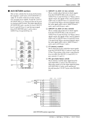
... AUX buses 1 and 2. 2 GROUP 3/4, AUX 3/4 mix controls These controls adjust the level at which signals from the AUX RETURN 2 jacks are sent to the ST bus. L (MONO) AUX RETURN 1 R L (MONO) AUX RETURN 2 R GROUP 1 GROUP 2 AUX 1 AUX 2 ST PFL GROUP 3 GROUP 4 AUX 3 AUX 4 ST PFL GROUP AUX ST PFL/AFL 1234 123456 LR LR AUX RETURN section signal flow -Owner's Manual By using the L and R jacks of the stereo control knobs does not affect the GROUP 1-4 and AUX 1-4 mix controls (1 and 2). 4 PFL (pre-fader listen) switch These switches send the input signal from the C-R OUT jacks...
... AUX buses 1 and 2. 2 GROUP 3/4, AUX 3/4 mix controls These controls adjust the level at which signals from the AUX RETURN 2 jacks are sent to the ST bus. L (MONO) AUX RETURN 1 R L (MONO) AUX RETURN 2 R GROUP 1 GROUP 2 AUX 1 AUX 2 ST PFL GROUP 3 GROUP 4 AUX 3 AUX 4 ST PFL GROUP AUX ST PFL/AFL 1234 123456 LR LR AUX RETURN section signal flow -Owner's Manual By using the L and R jacks of the stereo control knobs does not affect the GROUP 1-4 and AUX 1-4 mix controls (1 and 2). 4 PFL (pre-fader listen) switch These switches send the input signal from the C-R OUT jacks...
GF24/12 GF16/12 GF12/12 Owners Manual
Page 14
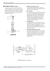
... IN switch (3). 14 Front and rear panel s TAPE IN section This section controls the signal that is sent from the TAPE IN jacks to the ST bus. PHANTOM +48V OFF ON 1 METER SELECT STEREO PFL•AFL GROUP TAPE IN 2 3 0 10 C-R MONITOR LEVEL 0 10 PHONES LEVEL 4 5 PHONES 6 -Owner's Manual s Other controls/connectors 1 PHANTOM +48 V (phantom power supply) switch This is the on , connecting an unbalanced device or a device whose level will show the output level of...
... IN switch (3). 14 Front and rear panel s TAPE IN section This section controls the signal that is sent from the TAPE IN jacks to the ST bus. PHANTOM +48V OFF ON 1 METER SELECT STEREO PFL•AFL GROUP TAPE IN 2 3 0 10 C-R MONITOR LEVEL 0 10 PHONES LEVEL 4 5 PHONES 6 -Owner's Manual s Other controls/connectors 1 PHANTOM +48 V (phantom power supply) switch This is the on , connecting an unbalanced device or a device whose level will show the output level of...
GF24/12 GF16/12 GF12/12 Owners Manual
Page 15
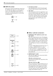
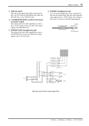
... stereo headphones can be monitored by the C-R OUT jacks and PHONES jack: either the PFL/AFL bus, or the TAPE IN jacks. 4 C-R MONITOR LEVEL (control room monitor level) control This adjusts the level of the signal that is sent to the C-R OUT jacks. This jack will be connected to this jack is as the C-R OUT jacks. Master controls 15 3 TAPE IN switch This selects the signal that will output the same signal as shown in the following diagram...
... stereo headphones can be monitored by the C-R OUT jacks and PHONES jack: either the PFL/AFL bus, or the TAPE IN jacks. 4 C-R MONITOR LEVEL (control room monitor level) control This adjusts the level of the signal that is sent to the C-R OUT jacks. This jack will be connected to this jack is as the C-R OUT jacks. Master controls 15 3 TAPE IN switch This selects the signal that will output the same signal as shown in the following diagram...
GF24/12 GF16/12 GF12/12 Owners Manual
Page 16
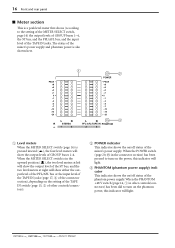
... setting of the METER SELECT switch, page 14) the output levels of GROUP buses 1-4, the ST bus, and the PFL/AFL bus, and the input level of GROUP buses 1-4. PEAK +8 +5 +3 +1 0 -1 -3 -5 -7 -10 -15 -20 1 2 POWER PEAK +8 +5 +3 +1 0 -1 -3 -5 -7 -10 -15 -20 L R STEREO 1 2 L R 3 PFL•AFL/TAPE IN PHANTOM 3 4 1 Level meters When the METER SELECT switch (page 14) is in other controls/connectors). 2 POWER indicator This indicator shows the on the phantom power, this indicator will light. 3 PHANTOM (phantom power supply...
... setting of the METER SELECT switch, page 14) the output levels of GROUP buses 1-4, the ST bus, and the PFL/AFL bus, and the input level of GROUP buses 1-4. PEAK +8 +5 +3 +1 0 -1 -3 -5 -7 -10 -15 -20 1 2 POWER PEAK +8 +5 +3 +1 0 -1 -3 -5 -7 -10 -15 -20 L R STEREO 1 2 L R 3 PFL•AFL/TAPE IN PHANTOM 3 4 1 Level meters When the METER SELECT switch (page 14) is in other controls/connectors). 2 POWER indicator This indicator shows the on the phantom power, this indicator will light. 3 PHANTOM (phantom power supply...
GF24/12 GF16/12 GF12/12 Owners Manual
Page 17
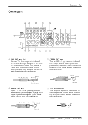
... -Owner's Manual The pin wiring is shown in the following diagram. Female XLR connector 2 (hot) 3 (cold) 1 (ground) 4 TAPE IN connector These are phono inputs jacks (unbalanced) for connecting external line level devices. These jacks can be connected to your foldback system or to the inputs of the main stereo output. Connectors Connectors 17 E DC B A 0 POWER ON/ OFF C-R OUT +4dB ST INSERT I/O 0dB AUX RETURN +4dB R LR L 2L (MONO) 1L INSERT...
... -Owner's Manual The pin wiring is shown in the following diagram. Female XLR connector 2 (hot) 3 (cold) 1 (ground) 4 TAPE IN connector These are phono inputs jacks (unbalanced) for connecting external line level devices. These jacks can be connected to your foldback system or to the inputs of the main stereo output. Connectors Connectors 17 E DC B A 0 POWER ON/ OFF C-R OUT +4dB ST INSERT I/O 0dB AUX RETURN +4dB R LR L 2L (MONO) 1L INSERT...
GF24/12 GF16/12 GF12/12 Owners Manual
Page 18
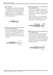
... phone input jacks (balanced) for the stereo input channels, with a nominal level of -10 dBV. This output signal is not affected by external effect processors connected to the ST INSERT I/O jacks (B) or by the position of the STEREO fader (page 12, 3 in the following diagram. 1/4" phone plug Tip (send) Sleeve (ground) 2 (hot) 8 INPUT B jacks 1-20 {1-12 on the GF16/12, 1-8 on , DC +48 V phantom power is shown in the STEREO/ MONO control section). 18 Front and rear panel 5 REC OUT jacks...
... phone input jacks (balanced) for the stereo input channels, with a nominal level of -10 dBV. This output signal is not affected by external effect processors connected to the ST INSERT I/O jacks (B) or by the position of the STEREO fader (page 12, 3 in the following diagram. 1/4" phone plug Tip (send) Sleeve (ground) 2 (hot) 8 INPUT B jacks 1-20 {1-12 on the GF16/12, 1-8 on , DC +48 V phantom power is shown in the STEREO/ MONO control section). 18 Front and rear panel 5 REC OUT jacks...
GF24/12 GF16/12 GF12/12 Owners Manual
Page 19
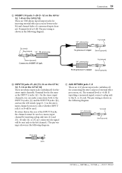
... -Owner's Manual Nominal level is shown in the following diagram. If inputting a monaural signal, connect a plug only to select whether INPUT jack A or B will be sent only to the left channel.) The pin wiring is the same as a mono input channel by inserting a plug only into 21L and 23L. (If only 21L or 23L are phono input jacks (unbalanced) for the stereo input channels. A AUX RETURN jacks 1/2 These are TRS phone input/output jacks for inserting external effect processors...
... -Owner's Manual Nominal level is shown in the following diagram. If inputting a monaural signal, connect a plug only to select whether INPUT jack A or B will be sent only to the left channel.) The pin wiring is the same as a mono input channel by inserting a plug only into 21L and 23L. (If only 21L or 23L are phono input jacks (unbalanced) for the stereo input channels. A AUX RETURN jacks 1/2 These are TRS phone input/output jacks for inserting external effect processors...
GF24/12 GF16/12 GF12/12 Owners Manual
Page 20
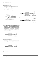
... switch turns the power of GROUP buses 1-4. Tip (send) Ring (return) 1/4" TRS phone plug Sleeve (ground) Connect to INSERT I /O jacks These are 1/4" phone output jacks (unbalanced) for inserting external effect processors between the ST bus and the STEREO fader. The nominal output level is shown in the following diagram. 1/4" phone plug Tip (send) Sleeve (ground) D GROUP OUT jacks 1-4 These are 1/4" phone jacks (unbalanced) which individually output the signals of the mixer on or off. -Owner's Manual 1/4" phone plug Tip (send) To processor's input...
... switch turns the power of GROUP buses 1-4. Tip (send) Ring (return) 1/4" TRS phone plug Sleeve (ground) Connect to INSERT I /O jacks These are 1/4" phone output jacks (unbalanced) for inserting external effect processors between the ST bus and the STEREO fader. The nominal output level is shown in the following diagram. 1/4" phone plug Tip (send) Sleeve (ground) D GROUP OUT jacks 1-4 These are 1/4" phone jacks (unbalanced) which individually output the signals of the mixer on or off. -Owner's Manual 1/4" phone plug Tip (send) To processor's input...

GF24/12 GF16/12 GF12/12 Owners Manual
Page 21
... 600Ω (GROUP OUT, AUX OUT, ST OUT, MONO OUT) -128 dB equivalent input noise -95 dB residual output noise (GROUP OUT, AUX OUT, ST OUT, MONO OUT) -86 dB (GROUP OUT, ST OUT, MONO OUT) Master fader: nominal level All channel faders: minimum All channel assign switches: off -81 dB (AUX OUT) Master fader: nominal level All channel faders, all AUX level controls: minimum -64 dB (68 dB S/N) (GROUP OUT, AUX OUT, ST OUT) Master fader, one channel fader, AUX level control: nominal level, Assign switch: on One channel gain control: maximum 84...
... 600Ω (GROUP OUT, AUX OUT, ST OUT, MONO OUT) -128 dB equivalent input noise -95 dB residual output noise (GROUP OUT, AUX OUT, ST OUT, MONO OUT) -86 dB (GROUP OUT, ST OUT, MONO OUT) Master fader: nominal level All channel faders: minimum All channel assign switches: off -81 dB (AUX OUT) Master fader: nominal level All channel faders, all AUX level controls: minimum -64 dB (68 dB S/N) (GROUP OUT, AUX OUT, ST OUT) Master fader, one channel fader, AUX level control: nominal level, Assign switch: on One channel gain control: maximum 84...
GF24/12 GF16/12 GF12/12 Owners Manual
Page 22
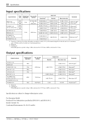
... the nominal output level when the unit is set at maximum gain. (All faders and level controls are subject to 0.775 Vrms, 0 dBV is referenced 1 Vrms. Connector XLR-3-32 type†1 Phone jack†2 Phone jack†1 Phone jack†2 Phono jack†2 Phone jack (I /O)†3 †1. 22 Specifications Input specifications Input terminals Gain Actual load For use with trim impedance nominal Sensitivity†1 Input level Nominal...
... the nominal output level when the unit is set at maximum gain. (All faders and level controls are subject to 0.775 Vrms, 0 dBV is referenced 1 Vrms. Connector XLR-3-32 type†1 Phone jack†2 Phone jack†1 Phone jack†2 Phono jack†2 Phone jack (I /O)†3 †1. 22 Specifications Input specifications Input terminals Gain Actual load For use with trim impedance nominal Sensitivity†1 Input level Nominal...


