
Owner's Manual
Page 2
... Input Signals 35 Using the EQ Library 36 Compressing the Input Signals 37 Using the Internal Effects 38 Recording to DAW Software via the USB Port 39 Adjusting the Monitor Levels from the DAW 41 Using Scene Memories 42 Changing the Channel Names 43 Creating a Custom Layer by ...Input Spec 61 Analog Output Specs 61 Digital Input Spec 62 Digital Output Spec 62 I/O SLOT Spec 63 MIDI/USB/WORD CLOCK I/O Spec .... 64 Dimensions 64 Options 65 Rack Mounting the 01V96i Using RK1 Rack Mount Kit 65 Index 66 01V96i Block Diagram.......End of Manual 01V96i Level Diagram .......End of Manual...
... Input Signals 35 Using the EQ Library 36 Compressing the Input Signals 37 Using the Internal Effects 38 Recording to DAW Software via the USB Port 39 Adjusting the Monitor Levels from the DAW 41 Using Scene Memories 42 Changing the Channel Names 43 Creating a Custom Layer by ...Input Spec 61 Analog Output Specs 61 Digital Input Spec 62 Digital Output Spec 62 I/O SLOT Spec 63 MIDI/USB/WORD CLOCK I/O Spec .... 64 Dimensions 64 Options 65 Rack Mounting the 01V96i Using RK1 Rack Mount Kit 65 Index 66 01V96i Block Diagram.......End of Manual 01V96i Level Diagram .......End of Manual...
Owner's Manual
Page 7
...back up the settings of the console, and to your computer. ■ Yamaha Steinberg USB Driver This is driver software for connecting the 01V96i to create setups even when the physical console is not available. 01V96i Editor runs within the platform software "Studio Manager Version 2." ■ Studio ...software. Refer to save or recall settings for any damages, either direct or consequential, that may result from the Yamaha Pro Audio website. The compact 01V96i Digital Console features 24-bit/96 kHz digital audio processing without compromise, as well as 40-channel simultaneous mixing. ...
...back up the settings of the console, and to your computer. ■ Yamaha Steinberg USB Driver This is driver software for connecting the 01V96i to create setups even when the physical console is not available. 01V96i Editor runs within the platform software "Studio Manager Version 2." ■ Studio ...software. Refer to save or recall settings for any damages, either direct or consequential, that may result from the Yamaha Pro Audio website. The compact 01V96i Digital Console features 24-bit/96 kHz digital audio processing without compromise, as well as 40-channel simultaneous mixing. ...
Owner's Manual
Page 8
..., add functionality, or fix problems. Firmware updates are performed with the product connected to a computer, so you must first install the "Yamaha Steinberg USB Driver" in your computer. By using "Adobe®Reader®" to the ON button." You can select display pages by using update software...20 for details on the website. The latest version of Adobe Reader can select pages. 01V96i-Owner's Manual In order to physical buttons are conveniences available only in this Manual The 01V96i features two types of buttons: physical buttons that you can press (e.g., ENTER and DISPLAY) ...
..., add functionality, or fix problems. Firmware updates are performed with the product connected to a computer, so you must first install the "Yamaha Steinberg USB Driver" in your computer. By using "Adobe®Reader®" to the ON button." You can select display pages by using update software...20 for details on the website. The latest version of Adobe Reader can select pages. 01V96i-Owner's Manual In order to physical buttons are conveniences available only in this Manual The 01V96i features two types of buttons: physical buttons that you can press (e.g., ENTER and DISPLAY) ...
Owner's Manual
Page 16
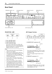
... These balanced TRS phone-type connectors output monitoring signals or 2TR IN signals. Note: • Make sure that this switch is +4 dB. 01V96i-Owner's Manual Doing so will cause malfunctions. • Do not connect or disconnect a device while phantom power is on. You can select ...signals or channel Direct Out signals. 16 Control Surface & Rear Panel Rear Panel PHANTOM +48V (p. 16) AD Output Section (p. 16) Digital I/O Section (p. 17) MIDI/USB Section (p. 17) Power Section (p. 18) PHANTOM +48V SLOT Section (p. 18) AD Output Section 3 2 1 1 CH1-4 ON/OFF switch 2 CH5-8 ON/OFF...
... These balanced TRS phone-type connectors output monitoring signals or 2TR IN signals. Note: • Make sure that this switch is +4 dB. 01V96i-Owner's Manual Doing so will cause malfunctions. • Do not connect or disconnect a device while phantom power is on. You can select ...signals or channel Direct Out signals. 16 Control Surface & Rear Panel Rear Panel PHANTOM +48V (p. 16) AD Output Section (p. 16) Digital I/O Section (p. 17) MIDI/USB Section (p. 17) Power Section (p. 18) PHANTOM +48V SLOT Section (p. 18) AD Output Section 3 2 1 1 CH1-4 ON/OFF switch 2 CH5-8 ON/OFF...
Owner's Manual
Page 17
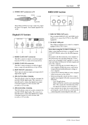
...the power conservation (suspend/sleep/standby/hibernate) settings of at least six seconds between disconnecting and reconnecting the USB cable. 01V96i-Owner's Manual Note when using the TO HOST USB port When connecting the 01V96i to connect the digital stereo input (consumer format) of a DAT recorder, MD recorder, or CD ...These standard MIDI IN, OUT and THRU ports enable you to connect the 01V96i to other MIDI equipment. 2 TO HOST USB port This USB port enables you fail to connect a computer equipped with a USB 2.0 port. The nominal signal level is typically used to connect the digital ...
...the power conservation (suspend/sleep/standby/hibernate) settings of at least six seconds between disconnecting and reconnecting the USB cable. 01V96i-Owner's Manual Note when using the TO HOST USB port When connecting the 01V96i to connect the digital stereo input (consumer format) of a DAT recorder, MD recorder, or CD ...These standard MIDI IN, OUT and THRU ports enable you to connect the 01V96i to other MIDI equipment. 2 TO HOST USB port This USB port enables you fail to connect a computer equipped with a USB 2.0 port. The nominal signal level is typically used to connect the digital ...

Owner's Manual
Page 19
... Operating Basics 19 Operating Basics This chapter describes basic operations on the 01V96i, including how to select a display page. If the selected Scene is receiving MIDI data via the MIDI IN port, USB port, or an installed card. 6 Surround mode indicator This indicator identifies... the currently-selected Surround mode (ST=stereo, 3-1, 5.1, or 6.1). 7 Sampling rate indicator This indicator identifies the 01V96i's current sampling rate: 44.1 kHz (44k), 48 ...
... Operating Basics 19 Operating Basics This chapter describes basic operations on the 01V96i, including how to select a display page. If the selected Scene is receiving MIDI data via the MIDI IN port, USB port, or an installed card. 6 Surround mode indicator This indicator identifies... the currently-selected Surround mode (ST=stereo, 3-1, 5.1, or 6.1). 7 Sampling rate indicator This indicator identifies the 01V96i's current sampling rate: 44.1 kHz (44k), 48 ...

Owner's Manual
Page 26
... be used as an audio interface with 16-channel input and output. The 01V96i's remote functionality can also be used to perform locate and transport operations on the DAW, and to... a computer-based DAW (Digital Audio Workstation). 26 Connections and Setup ■ Configuring a recording system that uses a DAW (Digital Audio Workstation) Computer TO HOST USB port Effects processor Synthesizer REC SONG SCENE INPUT connector OMNI OUT connector CH1-4 CH5-8 CH9-12 1 2 3 4 5 6 7 8 9 10 11 12 13 15 PHANTOM +48V A A A A A A A A A A A A 14 B B B...
... be used as an audio interface with 16-channel input and output. The 01V96i's remote functionality can also be used to perform locate and transport operations on the DAW, and to... a computer-based DAW (Digital Audio Workstation). 26 Connections and Setup ■ Configuring a recording system that uses a DAW (Digital Audio Workstation) Computer TO HOST USB port Effects processor Synthesizer REC SONG SCENE INPUT connector OMNI OUT connector CH1-4 CH5-8 CH9-12 1 2 3 4 5 6 7 8 9 10 11 12 13 15 PHANTOM +48V A A A A A A A A A A A A 14 B B B...

Owner's Manual
Page 28
... input from the ADAT IN connector on the type of sync with the current 01V96i internal clock. The number of pairs depends on the rear panel. Inputs are explained below . However, USB only displays the synchronization status, and cannot be selected as the wordclock source. The... I /O card installed. • adat These buttons select the inputs from the TO HOST USB port. This input is present at higher sampling frequencies (88.2 kHz or 96 kHz) between the 01V96i and connected external devices, you change the wordclock settings on the rear panel. • 2TRD...
... input from the ADAT IN connector on the type of sync with the current 01V96i internal clock. The number of pairs depends on the rear panel. Inputs are explained below . However, USB only displays the synchronization status, and cannot be selected as the wordclock source. The... I /O card installed. • adat These buttons select the inputs from the TO HOST USB port. This input is present at higher sampling frequencies (88.2 kHz or 96 kHz) between the 01V96i and connected external devices, you change the wordclock settings on the rear panel. • 2TRD...

Owner's Manual
Page 29
...but - Use the cursor buttons to confirm the change. Press [ENTER] to move the cur- Press the DISPLAY ACCESS [PATCH] but - TO HOST USB port chan- Stereo Out L & R Tip: • The STEREO OUT connectors always output the Stereo Bus signals. • The MONITOR OUT connectors ...default patching, recall Input Patch memory #00. ton repeatedly until the following page appears. 1 01V96i-Owner's Manual Connections and Setup Input and Output Patching 29 Input and Output Patching The 01V96i is designed to enable you to patch (assign) signals to view or change the patching....
...but - Use the cursor buttons to confirm the change. Press [ENTER] to move the cur- Press the DISPLAY ACCESS [PATCH] but - TO HOST USB port chan- Stereo Out L & R Tip: • The STEREO OUT connectors always output the Stereo Bus signals. • The MONITOR OUT connectors ...default patching, recall Input Patch memory #00. ton repeatedly until the following page appears. 1 01V96i-Owner's Manual Connections and Setup Input and Output Patching 29 Input and Output Patching The 01V96i is designed to enable you to patch (assign) signals to view or change the patching....

Owner's Manual
Page 30
...repeatedly until the fol- Input Channels 1-32 Insert Outs • INS BUS1-INS BUS8.... Press [ENTER] to USB OUT. • USB OUT1-8 ..... Patching output signals to USB OUT By default, the following output signals are assigned to confirm the change. The parameter boxes underneath each number indicate.... 1. Bus Out 1-8 signals If you wish to change, and rotate the Parameter wheel or press the [INC]/[DEC] buttons to change . 01V96i-Owner's Manual The meaning of these indicators are explained below No assignment • BUS1-BUS8 Bus Out 1-8 signals • AUX1-AUX8 Aux Out...
...repeatedly until the fol- Input Channels 1-32 Insert Outs • INS BUS1-INS BUS8.... Press [ENTER] to USB OUT. • USB OUT1-8 ..... Patching output signals to USB OUT By default, the following output signals are assigned to confirm the change. The parameter boxes underneath each number indicate.... 1. Bus Out 1-8 signals If you wish to change, and rotate the Parameter wheel or press the [INC]/[DEC] buttons to change . 01V96i-Owner's Manual The meaning of these indicators are explained below No assignment • BUS1-BUS8 Bus Out 1-8 signals • AUX1-AUX8 Aux Out...
Owner's Manual
Page 39
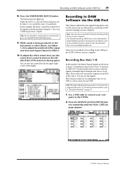
...For details on how to do this method if you want to record must have installed the Yamaha Steinberg USB Driver on the top panel. ton repeatedly until the Patch | USB Out page appears. Tutorial 01V96i-Owner's Manual In this method, the Input Channel signals are lit, faders 1-16 control the ... the signals. puter to normal mode, press the FADER MODE [HOME] button. 9. You can be assigned to connect your computer. The Yamaha Steinberg USB Driver can view the current level in the download file. Press the FADER MODE [AUX1] button. http://www.yamahaproaudio.com/ There are two...
...For details on how to do this method if you want to record must have installed the Yamaha Steinberg USB Driver on the top panel. ton repeatedly until the Patch | USB Out page appears. Tutorial 01V96i-Owner's Manual In this method, the Input Channel signals are lit, faders 1-16 control the ... the signals. puter to normal mode, press the FADER MODE [HOME] button. 9. You can be assigned to connect your computer. The Yamaha Steinberg USB Driver can view the current level in the download file. Press the FADER MODE [AUX1] button. http://www.yamahaproaudio.com/ There are two...
Owner's Manual
Page 40
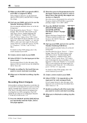
...Assign 1-16 to DAW tracks 1-16. 1. Signals of multiple Input Channels each monaural track. As the ASIO driver, choose "Yamaha Steinberg USB ASIO" (Windows) / "Yamaha 01V96i" (Mac). • From the "Device" menu, choose "VST Connections." For details on other DAW settings, refer to ..."Configuration" to Stereo and "Number" to 1, and click [OK] to create sixteen new monaural inputs. As the ASIO driver, choose "Yamaha Steinberg USB ASIO" (Windows) / "Yamaha 01V96i" (Mac). • From the "Device" menu, choose "VST Connections." In the Input tab choose [Add Bus], set "Configuration"...
...Assign 1-16 to DAW tracks 1-16. 1. Signals of multiple Input Channels each monaural track. As the ASIO driver, choose "Yamaha Steinberg USB ASIO" (Windows) / "Yamaha 01V96i" (Mac). • From the "Device" menu, choose "VST Connections." For details on other DAW settings, refer to ..."Configuration" to Stereo and "Number" to 1, and click [OK] to create sixteen new monaural inputs. As the ASIO driver, choose "Yamaha Steinberg USB ASIO" (Windows) / "Yamaha 01V96i" (Mac). • From the "Device" menu, choose "VST Connections." In the Input tab choose [Add Bus], set "Configuration"...

Owner's Manual
Page 41
...and the [ON] buttons will affect the monitoring signal, but - Tutorial 01V96i-Owner's Manual Here we'll explain the procedure for sending the signals of the song. As the ASIO driver, choose "Yamaha Steinberg USB ASIO" (Windows) / "Yamaha 01V96i" (Mac). • From the "Device" menu, choose "VST ...Connections." tively as necessary. Input Channel Layer 17-32 is sent to an 01V96i Input Channel for control from the channel strip section....
...and the [ON] buttons will affect the monitoring signal, but - Tutorial 01V96i-Owner's Manual Here we'll explain the procedure for sending the signals of the song. As the ASIO driver, choose "Yamaha Steinberg USB ASIO" (Windows) / "Yamaha 01V96i" (Mac). • From the "Device" menu, choose "VST ...Connections." tively as necessary. Input Channel Layer 17-32 is sent to an 01V96i Input Channel for control from the channel strip section....
Owner's Manual
Page 50
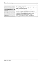
... Troubleshooting Signal level is low at specific frequencies. ❍ Refer to the 01V96i Editor installation guide on the website. ❍ Have you downloaded and installed the Yamaha Steinberg USB Driver? ❍ You must connect the 01V96i to the computer and power-on the 01V96i before you start up your DAW software. ❍ Check the driver...
... Troubleshooting Signal level is low at specific frequencies. ❍ Refer to the 01V96i Editor installation guide on the website. ❍ Have you downloaded and installed the Yamaha Steinberg USB Driver? ❍ You must connect the 01V96i to the computer and power-on the 01V96i before you start up your DAW software. ❍ Check the driver...
Owner's Manual
Page 51
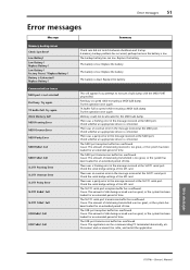
... buffer has overflowed. A memory backup problem has occurred, perhaps because the battery is low. The battery is low. Low Battery ! Full USB TxBuf. Check the serial bridge settings of time. Cause: The amount of data being transmitted is too great, or the system has been ... Battery ! There was a framing error in the message received at the MIDI port. Port busy. Try the operation once again. Error messages 01V96i-Owner's Manual Factory Preset ? TX buffer full. Full Summary Check sum did not match between shutdown and startup. There was an overrun error ...
... buffer has overflowed. A memory backup problem has occurred, perhaps because the battery is low. The battery is low. Low Battery ! Full USB TxBuf. Check the serial bridge settings of time. Cause: The amount of data being transmitted is too great, or the system has been ... Battery ! There was a framing error in the message received at the MIDI port. Port busy. Try the operation once again. Error messages 01V96i-Owner's Manual Factory Preset ? TX buffer full. Full Summary Check sum did not match between shutdown and startup. There was an overrun error ...

Owner's Manual
Page 55
... Number of scene memories 99 Internal 44.1 kHz, 48 kHz, 88.2 kHz, 96 kHz Sampling Frequency Signal Delay External fs=48 kHz fs=96 kHz USB audio The others Normal Rate Double Rate Normal rate: Double rate: 44.1 kHz ±0.1% 48 kHz ±0.1% 88.2 kHz ±0.1% 96 kHz ±0.1% 44.1 ... one CH INPUT fader at digital domain 24-bit linear, 128-times oversampling (fs=44.1, 48 kHz), 64-times oversampling (fs=88.2, 96 kHz) Specifications 01V96i-Owner's Manual Input Pad=0 dB Input Pad=0 dB Input Sensitivity =-60 dB 110 dB typ. AD+DA (to -16), detented AD Input (1-12) Peak indicator...
... Number of scene memories 99 Internal 44.1 kHz, 48 kHz, 88.2 kHz, 96 kHz Sampling Frequency Signal Delay External fs=48 kHz fs=96 kHz USB audio The others Normal Rate Double Rate Normal rate: Double rate: 44.1 kHz ±0.1% 48 kHz ±0.1% 88.2 kHz ±0.1% 96 kHz ±0.1% 44.1 ... one CH INPUT fader at digital domain 24-bit linear, 128-times oversampling (fs=44.1, 48 kHz), 64-times oversampling (fs=88.2, 96 kHz) Specifications 01V96i-Owner's Manual Input Pad=0 dB Input Pad=0 dB Input Sensitivity =-60 dB 110 dB typ. AD+DA (to -16), detented AD Input (1-12) Peak indicator...

Owner's Manual
Page 64
...Screw Heads) 350 101 350 540 548 Unit: mm Specifications and descriptions in every locale, please check with your Yamaha dealer. Since specifications, equipment or options may not be the same in this owner's manual are for information purposes... only. MIDI IN can use as TIME CODE IN MTC. - - - - Yamaha Corp. 64 Specifications MIDI/USB/WORD CLOCK I/O Spec I/O Port Format Level TO HOST USB USB 2.0 MIDI WORD CLOCK IN1 OUT THRU IN OUT MIDI MIDI MIDI - - 1. European Models... notice. reserves the right to Environments: E1, E2, E3 and E4 01V96i-Owner's Manual
...Screw Heads) 350 101 350 540 548 Unit: mm Specifications and descriptions in every locale, please check with your Yamaha dealer. Since specifications, equipment or options may not be the same in this owner's manual are for information purposes... only. MIDI IN can use as TIME CODE IN MTC. - - - - Yamaha Corp. 64 Specifications MIDI/USB/WORD CLOCK I/O Spec I/O Port Format Level TO HOST USB USB 2.0 MIDI WORD CLOCK IN1 OUT THRU IN OUT MIDI MIDI MIDI - - 1. European Models... notice. reserves the right to Environments: E1, E2, E3 and E4 01V96i-Owner's Manual

Owner's Manual
Page 66
...button 14 M MASTER button 13 Master page 23 Metering 23 MIDI button 12 MIDI IN/THRU/OUT ports 17 MIDI indicator 19 MIDI/USB Section 17 mini-YGDAI (Yamaha General Digital Audio Interface) I /O Section 17 DIO/SETUP button 12 Direct Outs 33 Display 13, 19 DISPLAY ACCESS Section 12 ...Firmware updates 8 FREQUENCY control 14 G G (Gain 36 GAIN control 10, 14 GATE GR 24 H H. 66 Index Index Symbols /INSERT/DELAY button 12 Numerics 01V96i Editor 7 1-16/17-32 buttons 13 1-8 46 1-8 buttons 14 1-8 buttons (Routing 34 2TR IN DIGITAL COAXIAL 17 2TR IN/OUT connectors 11 2TR OUT ...
...button 14 M MASTER button 13 Master page 23 Metering 23 MIDI button 12 MIDI IN/THRU/OUT ports 17 MIDI indicator 19 MIDI/USB Section 17 mini-YGDAI (Yamaha General Digital Audio Interface) I /O Section 17 DIO/SETUP button 12 Direct Outs 33 Display 13, 19 DISPLAY ACCESS Section 12 ...Firmware updates 8 FREQUENCY control 14 G G (Gain 36 GAIN control 10, 14 GATE GR 24 H H. 66 Index Index Symbols /INSERT/DELAY button 12 Numerics 01V96i Editor 7 1-16/17-32 buttons 13 1-8 46 1-8 buttons 14 1-8 buttons (Routing 34 2TR IN DIGITAL COAXIAL 17 2TR IN/OUT connectors 11 2TR OUT ...
Owner's Manual
Page 67
... 14 Studio Manager 7 Surround mode indicator 19 Synchronization status 28 Synchronize 27 T Tab Scroll 13 TITLE 46 Title Edit Window 21 TO HOST USB port 17 U USB 2.0 port 17 USB OUT 30 User Assignable Layer 44 User Define Select window 46 User Defined Keys 46 USER DEFINED KEYS Section ..........14 UTILITY button 12... button 13 W WAVEFORM 45 WORD CLOCK IN connector 17 WORD CLOCK OUT connector .......17 Wordclock 27 Wordclock master 27 Wordclock slave 27 Wordclock Source 28 Y Yamaha Steinberg USB Driver 7 Index 67 Index 01V96i-Owner's Manual
... 14 Studio Manager 7 Surround mode indicator 19 Synchronization status 28 Synchronize 27 T Tab Scroll 13 TITLE 46 Title Edit Window 21 TO HOST USB port 17 U USB 2.0 port 17 USB OUT 30 User Assignable Layer 44 User Define Select window 46 User Defined Keys 46 USER DEFINED KEYS Section ..........14 UTILITY button 12... button 13 W WAVEFORM 45 WORD CLOCK IN connector 17 WORD CLOCK OUT connector .......17 Wordclock 27 Wordclock master 27 Wordclock slave 27 Wordclock Source 28 Y Yamaha Steinberg USB Driver 7 Index 67 Index 01V96i-Owner's Manual
Reference Manual
Page 3
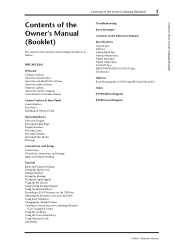
... EQ'ing the Input Signals Using the EQ Library Compressing the Input Signals Using the Internal Effects Recording to DAW Software via the USB Port Adjusting the Monitor Levels from the DAW Using Scene Memories Changing the Channel Names Creating a Custom Layer by Combining Channels (User... Manual Specifications General Spec Libraries Analog Input Spec Analog Output Specs Digital Input Spec Digital Output Spec I/O SLOT Spec MIDI/USB/WORD CLOCK I/O Spec Dimensions Options Rack Mounting the 01V96i Using RK1 Rack Mount Kit Index 01V96i Block Diagram 01V96i Level Diagram 01V96i-Reference Manual
... EQ'ing the Input Signals Using the EQ Library Compressing the Input Signals Using the Internal Effects Recording to DAW Software via the USB Port Adjusting the Monitor Levels from the DAW Using Scene Memories Changing the Channel Names Creating a Custom Layer by Combining Channels (User... Manual Specifications General Spec Libraries Analog Input Spec Analog Output Specs Digital Input Spec Digital Output Spec I/O SLOT Spec MIDI/USB/WORD CLOCK I/O Spec Dimensions Options Rack Mounting the 01V96i Using RK1 Rack Mount Kit Index 01V96i Block Diagram 01V96i Level Diagram 01V96i-Reference Manual


