
Owner's Manual
Page 39
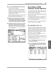
...the Input Channel signals are first sent to buses 1-8 and then routed to Bus Outs 1-8 and sent to the 01V96i. 2. Tutorial 01V96i-Owner's Manual In this , refer to normal mode, press the FADER MODE [HOME] button. 9. Recording to ...the send level of multiple Input Channels and stereo-record them. The Yamaha Steinberg USB Driver can be downloaded from Input Channels 1-16 to the 01V96i can view the current level in the download file. Press the ...Outs 1-8 to a stereo track of the display. Tip: To reset the fader 1-16 function to "Setting the Routing" on your computer.
...the Input Channel signals are first sent to buses 1-8 and then routed to Bus Outs 1-8 and sent to the 01V96i. 2. Tutorial 01V96i-Owner's Manual In this , refer to normal mode, press the FADER MODE [HOME] button. 9. Recording to ...the send level of multiple Input Channels and stereo-record them. The Yamaha Steinberg USB Driver can be downloaded from Input Channels 1-16 to the 01V96i can view the current level in the download file. Press the ...Outs 1-8 to a stereo track of the display. Tip: To reset the fader 1-16 function to "Setting the Routing" on your computer.

Owner's Manual
Page 43
... name of a newly-entered Long name are listed from left to the OK button, then press [ENTER]. Press the DISPLAY ACCESS [PATCH] but- You can reset all port names to their default names by moving the cursor to the desired parame- Move the cursor to the INITIALIZE button, then pressing [ENTER... library. You can change output channel names, press the DISPLAY ACCESS [PATCH] button repeatedly until the Patch| In Name page appears. 13 2 4. Press [ENTER]. Tutorial 01V96i-Owner's Manual
... name of a newly-entered Long name are listed from left to the OK button, then press [ENTER]. Press the DISPLAY ACCESS [PATCH] but- You can reset all port names to their default names by moving the cursor to the desired parame- Move the cursor to the INITIALIZE button, then pressing [ENTER... library. You can change output channel names, press the DISPLAY ACCESS [PATCH] button repeatedly until the Patch| In Name page appears. 13 2 4. Press [ENTER]. Tutorial 01V96i-Owner's Manual

Owner's Manual
Page 44
...the cursor to USER ASSIGNABLE, then press [ENTER]. A confirmation window appears. 3. The 01V96i displays the page shown below. 1 4. Set the TARGET parameter to the YES button, then press [ENTER]. You can reset the assignment to default by moving the cursor to the CLEAR button and pressing [ENTER]. ...If you set the Remote Layer target to "USER ASSIGNABLE," you can use the faders and [ON] buttons to control the assigned channels. 01V96i-Owner's Manual This custom layer is called "User Assignable layer." 1. Use the LAYER [REMOTE] button to assign or recall the User Assignable...
...the cursor to USER ASSIGNABLE, then press [ENTER]. A confirmation window appears. 3. The 01V96i displays the page shown below. 1 4. Set the TARGET parameter to the YES button, then press [ENTER]. You can reset the assignment to default by moving the cursor to the CLEAR button and pressing [ENTER]. ...If you set the Remote Layer target to "USER ASSIGNABLE," you can use the faders and [ON] buttons to control the assigned channels. 01V96i-Owner's Manual This custom layer is called "User Assignable layer." 1. Use the LAYER [REMOTE] button to assign or recall the User Assignable...

Owner's Manual
Page 46
...functions that recalls a specific Scene or library memory or transmits MIDI messages), an extra parameter box appears on the right and specify the number. 01V96i-Owner's Manual A function is usually executed on the function selected in the 1-8 parameter boxes. See the Reference Manual for example, a function...stored in which enables you to assign functions to the selected buttons. 4 This page contains the following parameters: 1 INITIALIZE This button resets the contents of all eight buttons. The items that is selected when it appears inside the dotted box. In the same way, set...
...functions that recalls a specific Scene or library memory or transmits MIDI messages), an extra parameter box appears on the right and specify the number. 01V96i-Owner's Manual A function is usually executed on the function selected in the 1-8 parameter boxes. See the Reference Manual for example, a function...stored in which enables you to assign functions to the selected buttons. 4 This page contains the following parameters: 1 INITIALIZE This button resets the contents of all eight buttons. The items that is selected when it appears inside the dotted box. In the same way, set...

Owner's Manual
Page 48
...set - The factory default password is turned off. 2. Note: • If you initialize the 01V96i to the factory-preset values, all currently-recorded settings and restore the factory-preset values, and reset the Operation Lock password to the CLEAR button, then press [ENTER]. Make sure that the power ...to factory default set state. To reset the 01V96i to the 01V96i is "1234." Move the cursor to the OK button, then press [ENTER] to its initial setting. While holding down the SCENE MEM-...
...set - The factory default password is turned off. 2. Note: • If you initialize the 01V96i to the factory-preset values, all currently-recorded settings and restore the factory-preset values, and reset the Operation Lock password to the CLEAR button, then press [ENTER]. Make sure that the power ...to factory default set state. To reset the 01V96i to the 01V96i is "1234." Move the cursor to the OK button, then press [ENTER] to its initial setting. While holding down the SCENE MEM-...

Reference Manual
Page 22
...sep- Routing Input Channels You can patch signals to the Bus outs. The parameters on the DIO/Setup | Surround Bus Setup page. 01V96i-Reference Manual The actual assignment may vary, depending on the settings on these two pages (and the procedure for Input Channels 17-32 ... destinations, if necessary. 1. 22 Input Channels Panning Input Channels Input Channels can be panned in opposite directions. Press the [ENTER] button to reset the currently-selected Pan control to center. 2 MODE The MODE parameter determines how paired Input Channels are routed only to set the value. 1...
...sep- Routing Input Channels You can patch signals to the Bus outs. The parameters on the DIO/Setup | Surround Bus Setup page. 01V96i-Reference Manual The actual assignment may vary, depending on the settings on these two pages (and the procedure for Input Channels 17-32 ... destinations, if necessary. 1. 22 Input Channels Panning Input Channels Input Channels can be panned in opposite directions. Press the [ENTER] button to reset the currently-selected Pan control to center. 2 MODE The MODE parameter determines how paired Input Channels are routed only to set the value. 1...

Reference Manual
Page 24
...is in . If the channel is not in one piece when channels are paired. The heart icon ( ) is selected. Press the [ENTER] button to reset the Fader to 0.0 dB. 2 SURROUND PAN section • SURROUND PAN The Surround pan parameters for the currently-selected Input Channel are not paired. (See.../OFF button This button turns on or off , the Follow Pan function is disabled and an identical signal is unavailable for the ST IN Channels.) 01V96i-Reference Manual The heart icon is broken ( ) when channels are displayed only when a Surround mode is in a group, "-" appears. (The compressor is ...
...is in . If the channel is not in one piece when channels are paired. The heart icon ( ) is selected. Press the [ENTER] button to reset the Fader to 0.0 dB. 2 SURROUND PAN section • SURROUND PAN The Surround pan parameters for the currently-selected Input Channel are not paired. (See.../OFF button This button turns on or off , the Follow Pan function is disabled and an identical signal is unavailable for the ST IN Channels.) 01V96i-Reference Manual The heart icon is broken ( ) when channels are displayed only when a Surround mode is in a group, "-" appears. (The compressor is ...

Reference Manual
Page 26
... can use the [SEL] buttons on the top panel or access the Pair/Grup pages. 01V96i-Reference Manual See page 21 for more information on Layer 1 and Layer 2 that are available for independent control) are listed below: Linked parameters Non-linked ... on the EQ | Edit and View pages. Tip: • Pressing and holding down the button selected in Step 2 resets the corresponding band gain. • Pressing the SELECTED CHANNEL [HIGH] and [LOW] buttons simultaneously resets the Q, frequency and gain for each channel independently on the EQ | ATT page, but the paired channel settings...
... can use the [SEL] buttons on the top panel or access the Pair/Grup pages. 01V96i-Reference Manual See page 21 for more information on Layer 1 and Layer 2 that are available for independent control) are listed below: Linked parameters Non-linked ... on the EQ | Edit and View pages. Tip: • Pressing and holding down the button selected in Step 2 resets the corresponding band gain. • Pressing the SELECTED CHANNEL [HIGH] and [LOW] buttons simultaneously resets the Q, frequency and gain for each channel independently on the EQ | ATT page, but the paired channel settings...

Reference Manual
Page 27
... odd channel parameter values to the even channel. • CH y ➔ x Copies the even channel parameter values to the odd channel. • RESET BOTH Resets both stereo channels. This mode is recalled). The mix parameters of the paired channels and pressing the second [SEL] button cancels the pair. Move the... you wish to pair, press the [SEL] button for a non-adjacent channel will pair Channels 1 and 17.) 3. The following buttons are paired. 01V96i-Reference Manual Pressing the [SEL] button for the adjacent channel. (The paired channel numbers should be ignored.
... odd channel parameter values to the even channel. • CH y ➔ x Copies the even channel parameter values to the odd channel. • RESET BOTH Resets both stereo channels. This mode is recalled). The mix parameters of the paired channels and pressing the second [SEL] button cancels the pair. Move the... you wish to pair, press the [SEL] button for a non-adjacent channel will pair Channels 1 and 17.) 3. The following buttons are paired. 01V96i-Reference Manual Pressing the [SEL] button for the adjacent channel. (The paired channel numbers should be ignored.

Reference Manual
Page 28
... Pair/Grup | Output page (see page 33). For example, it may be helpful for mixdown if you to change these names if desired. You can reset all channel names to their default names by moving the cursor to the Short name. ton, then press [ENTER]. Naming Input Channels By default, Input... to the INITIALIZE button, then pressing [ENTER]. 2. 28 Input Channels 4. Press the DISPLAY ACCESS [PATCH] button repeatedly until the Patch | IN Name page appears. 13 2 01V96i-Reference Manual You can also create or cancel a pair of the Long name.
... Pair/Grup | Output page (see page 33). For example, it may be helpful for mixdown if you to change these names if desired. You can reset all channel names to their default names by moving the cursor to the Short name. ton, then press [ENTER]. Naming Input Channels By default, Input... to the INITIALIZE button, then pressing [ENTER]. 2. 28 Input Channels 4. Press the DISPLAY ACCESS [PATCH] button repeatedly until the Patch | IN Name page appears. 13 2 01V96i-Reference Manual You can also create or cancel a pair of the Long name.

Reference Manual
Page 34
Attenuating Output Signals To attenuate the 01V96i's output signals, display the EQ | Out Att page and adjust the Stereo Out... attenuation. When this button is turned on, Aux Sends follow the Input Channel Surround Pan when the 01V96i is in the left column (1), then scroll the list up or down using the Parameter wheel to ...L & R channels 3. Move the cursor to -9 dB. ton repeatedly until the DIO/Setup | Output Att page appears. 1 2 01V96i-Reference Manual 2. Move the cursor to the parameter value in the right column (2), then rotate the Parameter wheel or press the [INC]/[...
Attenuating Output Signals To attenuate the 01V96i's output signals, display the EQ | Out Att page and adjust the Stereo Out... attenuation. When this button is turned on, Aux Sends follow the Input Channel Surround Pan when the 01V96i is in the left column (1), then scroll the list up or down using the Parameter wheel to ...L & R channels 3. Move the cursor to -9 dB. ton repeatedly until the DIO/Setup | Output Att page appears. 1 2 01V96i-Reference Manual 2. Move the cursor to the parameter value in the right column (2), then rotate the Parameter wheel or press the [INC]/[...

Reference Manual
Page 35
... names in the center column (1) and Long (full) names in the Output Patch library. 01V96i-Reference Manual Bus Outs Naming the Stereo Out and Bus Outs 35 Naming the Stereo Out and Bus Outs You can reset all bus names to their default names by moving the cursor to the INITIALIZE button...
... names in the center column (1) and Long (full) names in the Output Patch library. 01V96i-Reference Manual Bus Outs Naming the Stereo Out and Bus Outs 35 Naming the Stereo Out and Bus Outs You can reset all bus names to their default names by moving the cursor to the INITIALIZE button...

Reference Manual
Page 39
...In Variable mode, Aux Send levels, Aux On/Off, and Pre/Post parameters for paired Input Channels are linked to pre-fader or post-fader. 01V96i-Reference Manual These ON/OFF buttons turn on the current page) to each other . 5. You can select Variable or Fixed mode individually for the ...level rotary controls and PRE/POST buttons. 4. Channel Send level rotary controls and PRE/POST buttons appear on or off for paired Input Channels are reset to adjust the signal source points and Send levels. • Variable Mode In this mode, Aux Send levels are variable and the signal source...
...In Variable mode, Aux Send levels, Aux On/Off, and Pre/Post parameters for paired Input Channels are linked to pre-fader or post-fader. 01V96i-Reference Manual These ON/OFF buttons turn on the current page) to each other . 5. You can select Variable or Fixed mode individually for the ...level rotary controls and PRE/POST buttons. 4. Channel Send level rotary controls and PRE/POST buttons appear on or off for paired Input Channels are reset to adjust the signal source points and Send levels. • Variable Mode In this mode, Aux Send levels are variable and the signal source...

Reference Manual
Page 54
... 3 SURROUND PAN LFE LEVEL USB USB 1 USB 2 USB 3 USB 4 USB 5 USB 6 Track 1 Track 2 Track 3 Track 4 Track 5 Track 6 DAW 01V96i-Reference Manual For example, in 3-1 Surround mode, Bus Outs 1-4 are available. 8. Tip: • Pressing the DISPLAY ACCESS [SETUP] button repeat- Connect a playback device...3 1 2 1 BUS1-BUS8 These parameters select channels to be assigned to the Bus Outs in 3-1, 5.1, and 6.1 Surround modes. 2 INIT These buttons reset the channel assignment to the default setting. 3 Surround LR to the DAW's tracks. In 5.1 Surround mode, Bus Outs 1-6 are available, and in 6.1...
... 3 SURROUND PAN LFE LEVEL USB USB 1 USB 2 USB 3 USB 4 USB 5 USB 6 Track 1 Track 2 Track 3 Track 4 Track 5 Track 6 DAW 01V96i-Reference Manual For example, in 3-1 Surround mode, Bus Outs 1-4 are available. 8. Tip: • Pressing the DISPLAY ACCESS [SETUP] button repeat- Connect a playback device...3 1 2 1 BUS1-BUS8 These parameters select channels to be assigned to the Bus Outs in 3-1, 5.1, and 6.1 Surround modes. 2 INIT These buttons reset the channel assignment to the default setting. 3 Surround LR to the DAW's tracks. In 5.1 Surround mode, Bus Outs 1-6 are available, and in 6.1...

Reference Manual
Page 61
... [INC]/[DEC] buttons, or [ENTER] button to set the master levels for all Fader groups to turn the Solo function of each Fader group. 01V96i-Reference Manual The resultant Channel level equals the corresponding Channel fader level plus the Group Master level. • ALL NOMINAL This button... resets the master levels for the Fader groups. See page 110 for each Fader group on an analog mixing console. • Faders These faders ...
... [INC]/[DEC] buttons, or [ENTER] button to set the master levels for all Fader groups to turn the Solo function of each Fader group. 01V96i-Reference Manual The resultant Channel level equals the corresponding Channel fader level plus the Group Master level. • ALL NOMINAL This button... resets the master levels for the Fader groups. See page 110 for each Fader group on an analog mixing console. • Faders These faders ...
Reference Manual
Page 68
... which store 01V96i mix and...is a special read -only memory that are retained while the 01V96i is set to their parameter settings Remote Layer Fader and [... match Scene memory #2. 01V96i-Reference Manual The contents of the Scene that the current settings on the 01V96i, and the Edit indicator... the current settings on the 01V96i do not store the edited ...top of the display), indicating that contains the default settings of 01V96i channel mix settings and internal effects processor settings as a "Scene"...Data Nominal check box on the 01V96i to either 0 dB or - dB when Scene memory...
... which store 01V96i mix and...is a special read -only memory that are retained while the 01V96i is set to their parameter settings Remote Layer Fader and [... match Scene memory #2. 01V96i-Reference Manual The contents of the Scene that the current settings on the 01V96i, and the Edit indicator... the current settings on the 01V96i do not store the edited ...top of the display), indicating that contains the default settings of 01V96i channel mix settings and internal effects processor settings as a "Scene"...Data Nominal check box on the 01V96i to either 0 dB or - dB when Scene memory...

Reference Manual
Page 71
... set the Fade Time for each Scene individually or for each Bus Out (1-8) in unison with the Out Fade page. 2 ALL INPUT CLEAR This button resets all channel Fade Times on the In Fade page. Tip: You can specify the time it can be set for all Input Channels by double...-clicking the [ENTER] button. 01V96i-Reference Manual This is temporarily ignored.) This check box setting works in unison with its partner. The basic operation is temporarily ignored. • You can...
... set the Fade Time for each Scene individually or for each Bus Out (1-8) in unison with the Out Fade page. 2 ALL INPUT CLEAR This button resets all channel Fade Times on the In Fade page. Tip: You can specify the time it can be set for all Input Channels by double...-clicking the [ENTER] button. 01V96i-Reference Manual This is temporarily ignored.) This check box setting works in unison with its partner. The basic operation is temporarily ignored. • You can...

Reference Manual
Page 74
You can store library data to a computer hard disk using the included Studio Manager software. Recall memory #0 to reset the parameter settings to the YES button in the title column of the following libraries: • Channel Library • Input Patch Library ... window. 3 STORE This button stores the settings to "Title Edit Window" in the middle of the selected memory. Refer to the selected memory. The 01V96i offers the following func- The procedure for each library. 1. Recall #U to select the desired memory. tion buttons, then press [ENTER]. 1 TITLE EDIT...
You can store library data to a computer hard disk using the included Studio Manager software. Recall memory #0 to reset the parameter settings to the YES button in the title column of the following libraries: • Channel Library • Input Patch Library ... window. 3 STORE This button stores the settings to "Title Edit Window" in the middle of the selected memory. Refer to the selected memory. The 01V96i offers the following func- The procedure for each library. 1. Recall #U to select the desired memory. tion buttons, then press [ENTER]. 1 TITLE EDIT...

Reference Manual
Page 75
... Outs 1-8, or Stereo Out, with the alarm indicators displayed. (For unmatched parameter settings, the 01V96i will use the Channel library. 1. This preset memory resets all parameters of the cur- 1 Reset (0 dB) rently-selected channel to their initial values and sets the channel fader level to the... 25-32 ST IN Channels 1-4 INPUT connectors 1-16 ADAT IN Channels 1-8 Slot Channels 1-8 Internal Effects Processor 1-4 Outputs 1 & 2 01V96i-Reference Manual Use the LAYER buttons to select layers, then press the [SEL] buttons to store and recall Input Channel and Output Channel parameter...
... Outs 1-8, or Stereo Out, with the alarm indicators displayed. (For unmatched parameter settings, the 01V96i will use the Channel library. 1. This preset memory resets all parameters of the cur- 1 Reset (0 dB) rently-selected channel to their initial values and sets the channel fader level to the... 25-32 ST IN Channels 1-4 INPUT connectors 1-16 ADAT IN Channels 1-8 Slot Channels 1-8 Internal Effects Processor 1-4 Outputs 1 & 2 01V96i-Reference Manual Use the LAYER buttons to select layers, then press the [SEL] buttons to store and recall Input Channel and Output Channel parameter...

Reference Manual
Page 87
... Control parameters to adjust the currently-selected parameter, or execute the shuttle and scrub operation. Fast forwards the cursor position. 01V96i-Reference Manual While you to these buttons, you can adjust each of these buttons. If 16 or fewer channels are displayed... 6] button Press and hold down the [AUX 6] button, the SELECT ASSIGN parameter indicates "DFLT." • [AUX 7] button When this button to reset the corresponding channel fader level. Starts playback from the left-most channel. ■ FADER MODE Section • [AUX 1]-[AUX 5] buttons These buttons select...
... Control parameters to adjust the currently-selected parameter, or execute the shuttle and scrub operation. Fast forwards the cursor position. 01V96i-Reference Manual While you to these buttons, you can adjust each of these buttons. If 16 or fewer channels are displayed... 6] button Press and hold down the [AUX 6] button, the SELECT ASSIGN parameter indicates "DFLT." • [AUX 7] button When this button to reset the corresponding channel fader level. Starts playback from the left-most channel. ■ FADER MODE Section • [AUX 1]-[AUX 5] buttons These buttons select...
