
Owner's Manual
Page 8
... Display Interface 29 Selecting Layers 31 Selecting Channels 32 Selecting Fader Modes 33 Metering 34 4 Connections and Setup 37 Connections 37 Wordclock Connections and Settings 40 Input and Output Patching 43 5 Tutorial 47 Connections and Setup 47 Initial Track Recording 49 Overdubbing to Other Tracks 60 Mixing Recorded Tracks into Stereo (Mixdown 63... Outs 109 Aux Out 1-8 109 Setting Aux Out 1-8 from the Display 110 Viewing Aux Out settings 112 Setting Aux Out 1-8 from the Control Surface 113 01V96-Owner's Manual
... Display Interface 29 Selecting Layers 31 Selecting Channels 32 Selecting Fader Modes 33 Metering 34 4 Connections and Setup 37 Connections 37 Wordclock Connections and Settings 40 Input and Output Patching 43 5 Tutorial 47 Connections and Setup 47 Initial Track Recording 49 Overdubbing to Other Tracks 60 Mixing Recorded Tracks into Stereo (Mixdown 63... Outs 109 Aux Out 1-8 109 Setting Aux Out 1-8 from the Display 110 Viewing Aux Out settings 112 Setting Aux Out 1-8 from the Control Surface 113 01V96-Owner's Manual
Owner's Manual
Page 9
... 117 Panning Aux Sends 119 Copying Channel Fader Positions to Aux Sends 120 10 Input & Output Patching 121 Input Patching 121 Output Patching 123 Patching Direct Outs 125 Insert Patching 127 11 Monitoring 131 Monitor 131 Monitor and Solo Setup 132 Using the Monitor 133 Using the Solo Function 134 12 Surround Pan... Remote Function 185 Pro Tools Remote Layer 186 Nuendo Remote Layer 202 Other DAW Remote Layers 202 MIDI Remote Layer 203 Machine Control Function 208 01V96-Owner's Manual
... 117 Panning Aux Sends 119 Copying Channel Fader Positions to Aux Sends 120 10 Input & Output Patching 121 Input Patching 121 Output Patching 123 Patching Direct Outs 125 Insert Patching 127 11 Monitoring 131 Monitor 131 Monitor and Solo Setup 132 Using the Monitor 133 Using the Solo Function 134 12 Surround Pan... Remote Function 185 Pro Tools Remote Layer 186 Nuendo Remote Layer 202 Other DAW Remote Layers 202 MIDI Remote Layer 203 Machine Control Function 208 01V96-Owner's Manual
Owner's Manual
Page 10
...01V96 211 MIDI Port Setup 212 Assigning Scenes to Program Changes for Remote Recall 215 Assigning Parameters to Control Changes for Real-time Control 216 Controlling Parameters by Using Parameter Changes 221 Transmitting Parameter Settings via MIDI (Bulk Dump 222 19 Other Functions 225 Changing the Input...Battery and the System Version 238 Initializing the 01V96 239 Calibrating the Faders 240 Appendix A: Parameter Lists 241 USER DEFINED KEYS 241 USER DEFINED KEYS Initial Assignments 243 Input Patch Parameters 243 Initial Input Patch Settings 245 Output Patch Parameters 247 ...
...01V96 211 MIDI Port Setup 212 Assigning Scenes to Program Changes for Remote Recall 215 Assigning Parameters to Control Changes for Real-time Control 216 Controlling Parameters by Using Parameter Changes 221 Transmitting Parameter Settings via MIDI (Bulk Dump 222 19 Other Functions 225 Changing the Input...Battery and the System Version 238 Initializing the 01V96 239 Calibrating the Faders 240 Appendix A: Parameter Lists 241 USER DEFINED KEYS 241 USER DEFINED KEYS Initial Assignments 243 Input Patch Parameters 243 Initial Input Patch Settings 245 Output Patch Parameters 247 ...
Owner's Manual
Page 13
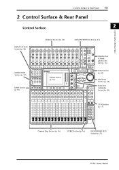
... 6 7 8 9 10 11 12 PHANTOM +48V 13 15 A A A A A A A A A A A A 14 B B B B B B B B B B B B INPUT (BAL) INSERT OUT IN (UNBAL) INSERT I/O INSERT I/O INSERT I/O INSERT I/O INSERT I/O INSERT I/O INSERT I/O INSERT I/O INSERT I/O INSERT I/O INSERT I/O INSERT I/O L 16 R IN OUT 2TR...LEVEL10 PHONES DISPLAY ACCESS SCENE MEMORY FADER MODE Section (p. 17) LAYER Section (p. 19) SCENE DIO/SETUP MIDI UTILITY / INSERT/ PAN/ PAIR/ DELAY ROUTING GROUP PATCH DYNAMICS EQ EFFECT FADER MODE VIEW AUX...USER DEFINED KEYS Section (p. 21) 01V96-Owner's Manual
... 6 7 8 9 10 11 12 PHANTOM +48V 13 15 A A A A A A A A A A A A 14 B B B B B B B B B B B B INPUT (BAL) INSERT OUT IN (UNBAL) INSERT I/O INSERT I/O INSERT I/O INSERT I/O INSERT I/O INSERT I/O INSERT I/O INSERT I/O INSERT I/O INSERT I/O INSERT I/O INSERT I/O L 16 R IN OUT 2TR...LEVEL10 PHONES DISPLAY ACCESS SCENE MEMORY FADER MODE Section (p. 17) LAYER Section (p. 19) SCENE DIO/SETUP MIDI UTILITY / INSERT/ PAN/ PAIR/ DELAY ROUTING GROUP PATCH DYNAMICS EQ EFFECT FADER MODE VIEW AUX...USER DEFINED KEYS Section (p. 21) 01V96-Owner's Manual
Owner's Manual
Page 18
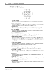
...page, enabling you to make MIDI settings (see page 87). 01V96-Owner's Manual L [VIEW] button This button displays a View page, enabling you to view and set up the 01V96, including digital input and output setup and remote control setup (see page 81). 18 Chapter 2-Control Surface & Rear ...Panel DISPLAY ACCESS Section 1 23 4 DISPLAY ACCESS 6 5 SCENE DIO/SETUP MIDI UTILITY / INSERT/ PAN/ PAIR/ DELAY ROUTING ...
...page, enabling you to make MIDI settings (see page 87). 01V96-Owner's Manual L [VIEW] button This button displays a View page, enabling you to view and set up the 01V96, including digital input and output setup and remote control setup (see page 81). 18 Chapter 2-Control Surface & Rear ...Panel DISPLAY ACCESS Section 1 23 4 DISPLAY ACCESS 6 5 SCENE DIO/SETUP MIDI UTILITY / INSERT/ PAN/ PAIR/ DELAY ROUTING ...
Owner's Manual
Page 37
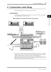
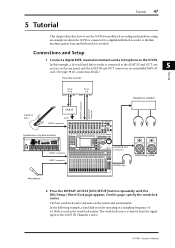
Connections and Setup 37 4 Connections and Setup This chapter explains how to connect and set up your AD card documentation. 01V96-Owner's Manual Master recorder Effects processor 88 Guitar SLOT INPUT connector OMNI OUT connector INPUT connector CH1-4 CH5-8 CH9-12 1 2 3 4 5 6 7 8 9 10 11 12 13 15 PHANTOM +48V A A A A A A A A A A A A 14 B B B B B B B B B B B B INPUT (BAL) INSERT OUT IN (UNBAL) INSERT I/O INSERT...
Connections and Setup 37 4 Connections and Setup This chapter explains how to connect and set up your AD card documentation. 01V96-Owner's Manual Master recorder Effects processor 88 Guitar SLOT INPUT connector OMNI OUT connector INPUT connector CH1-4 CH5-8 CH9-12 1 2 3 4 5 6 7 8 9 10 11 12 13 15 PHANTOM +48V A A A A A A A A A A A A 14 B B B B B B B B B B B B INPUT (BAL) INSERT OUT IN (UNBAL) INSERT I/O INSERT...
Owner's Manual
Page 38
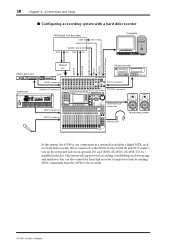
...Sequencer Real-time External Control Surface Modular Synthesis Plug-in System SCENE DIO/SETUP MIDI UTILITY / INSERT/ PAN/ PAIR/ DELAY ROUTING GROUP PATCH DYNAMICS ... 13 14 15 16 SEL SEL SEL SOLO SOLO ON ON ON ST IN 1 ST IN 2 2TR IN connector 2TR OUT connector MONITOR OUT connectors INPUT connector +10 0 +10 0 +10 0 +10 0 +10 0 +10 0 +10 0 +10 0 +10 0 +10 0 +10 0 +10 0 +10 0 +10 0 +10 0 +10 00 5 5 5 5 5 5 5 5 5 5 5 5 5 5 5 5 5 5... In this system, the 01V96 is connected to the recorder. 01V96-Owner's Manual You can also control the hard...
...Sequencer Real-time External Control Surface Modular Synthesis Plug-in System SCENE DIO/SETUP MIDI UTILITY / INSERT/ PAN/ PAIR/ DELAY ROUTING GROUP PATCH DYNAMICS ... 13 14 15 16 SEL SEL SEL SOLO SOLO ON ON ON ST IN 1 ST IN 2 2TR IN connector 2TR OUT connector MONITOR OUT connectors INPUT connector +10 0 +10 0 +10 0 +10 0 +10 0 +10 0 +10 0 +10 0 +10 0 +10 0 +10 0 +10 0 +10 0 +10 0 +10 0 +10 00 5 5 5 5 5 5 5 5 5 5 5 5 5 5 5 5 5 5... In this system, the 01V96 is connected to the recorder. 01V96-Owner's Manual You can also control the hard...
Owner's Manual
Page 39
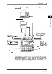
... 13 14 15 16 SEL SEL SEL SOLO SOLO ON ON ON ST IN 1 ST IN 2 2TR IN connector 2TR OUT connector MONITOR OUT connectors INPUT connector +10 0 +10 0 +10 0 +10 0 +10 0 +10 0 +10 0 +10 0 +10 0 +10 0 +10 0 +10 0 +10 0 +10 0 +10 0 +10 00 5 5 5 5 5 5 5 5 5 5 5 5 5 5 5 5 5 5 5 5 5 5 5 5 5 5 5 5 5 5 5 55 0... functions and change the parameters. 01V96-Owner's Manual Connections 39 ■ Configuring a recording system that uses a DAW (Digital Audio Workstation) Computer 4 Connections and Setup MIDI interface MIDI IN MIDI OUT...
... 13 14 15 16 SEL SEL SEL SOLO SOLO ON ON ON ST IN 1 ST IN 2 2TR IN connector 2TR OUT connector MONITOR OUT connectors INPUT connector +10 0 +10 0 +10 0 +10 0 +10 0 +10 0 +10 0 +10 0 +10 0 +10 0 +10 0 +10 0 +10 0 +10 0 +10 0 +10 00 5 5 5 5 5 5 5 5 5 5 5 5 5 5 5 5 5 5 5 5 5 5 5 5 5 5 5 5 5 5 5 55 0... functions and change the parameters. 01V96-Owner's Manual Connections 39 ■ Configuring a recording system that uses a DAW (Digital Audio Workstation) Computer 4 Connections and Setup MIDI interface MIDI IN MIDI OUT...
Owner's Manual
Page 41
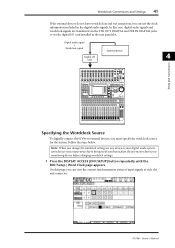
...30 BUS 6 15 31 BUS 7 16 32 BUS 8 STEREO Specifying the Wordclock Source To digitally connect the 01V96 to being out of input signals at each slot and connector. 01V96-Owner's Manual Note: When you change the wordclock settings on any device in your monitoring device before changing ...wordclock settings. 1 Press the DISPLAY ACCESS [DIO/SETUP] button repeatedly until the DIO/Setup | Word Clock page appears. In ...
...30 BUS 6 15 31 BUS 7 16 32 BUS 8 STEREO Specifying the Wordclock Source To digitally connect the 01V96 to being out of input signals at each slot and connector. 01V96-Owner's Manual Note: When you change the wordclock settings on any device in your monitoring device before changing ...wordclock settings. 1 Press the DISPLAY ACCESS [DIO/SETUP] button repeatedly until the DIO/Setup | Word Clock page appears. In ...
Owner's Manual
Page 42
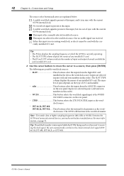
...; The IN and OUT columns indicate the number of any installed I /O card installed in this input is not receiving wordclock, or else it is in sync with the current 01V96 internal clock. 42 Chapter 4-Connections and Setup The source select button indicators are explained below: A usable wordclock signal is present at the WORD...
...; The IN and OUT columns indicate the number of any installed I /O card installed in this input is not receiving wordclock, or else it is in sync with the current 01V96 internal clock. 42 Chapter 4-Connections and Setup The source select button indicators are explained below: A usable wordclock signal is present at the WORD...
Owner's Manual
Page 43
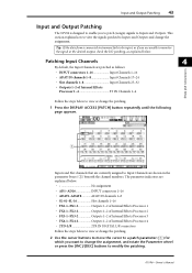
... are patched as follows: • INPUT connectors 1-16 Input Channels 1-16 • ADAT IN channels 1-8 Input Channels 17-24 • Slot channels 1-8 Input Channels 25-32 • Outputs 1-2 of Internal Effects Processor 1-4 ST IN Channels 1-4 Connections and Setup Follow the steps below to view or change the... which you to patch (assign) signals to Inputs and Outputs. This section explains how to view the signals patched to Inputs and Outputs and change the assignment. Input and Output Patching 43 Input and Output Patching The 01V96 is designed to enable you want to change the...
... are patched as follows: • INPUT connectors 1-16 Input Channels 1-16 • ADAT IN channels 1-8 Input Channels 17-24 • Slot channels 1-8 Input Channels 25-32 • Outputs 1-2 of Internal Effects Processor 1-4 ST IN Channels 1-4 Connections and Setup Follow the steps below to view or change the... which you to patch (assign) signals to Inputs and Outputs. This section explains how to view the signals patched to Inputs and Outputs and change the assignment. Input and Output Patching 43 Input and Output Patching The 01V96 is designed to enable you want to change the...
Owner's Manual
Page 44
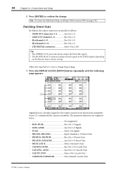
...connectors output monitor signals or the 2TR IN signals, depending on the Monitor Source selector setting. 44 Chapter 4-Connections and Setup 3 Press [ENTER] to confirm the change the patching. 1 Press the DISPLAY ACCESS [PATCH] button ... page appears. 1 Signals that are currently assigned to view or change . Tip: To restore the default patching, recall Input Patch memory #00 (see page 174). Follow the steps below No assignment • BUS1-BUS8 Bus Out 1-8 signals ...-L/ST-R Stereo Out Cascade Outs • CASSOLOL/CASSOLOR Solo Channel Cascade Outs 01V96-Owner's Manual
...connectors output monitor signals or the 2TR IN signals, depending on the Monitor Source selector setting. 44 Chapter 4-Connections and Setup 3 Press [ENTER] to confirm the change the patching. 1 Press the DISPLAY ACCESS [PATCH] button ... page appears. 1 Signals that are currently assigned to view or change . Tip: To restore the default patching, recall Input Patch memory #00 (see page 174). Follow the steps below No assignment • BUS1-BUS8 Bus Out 1-8 signals ...-L/ST-R Stereo Out Cascade Outs • CASSOLOL/CASSOLOR Solo Channel Cascade Outs 01V96-Owner's Manual

Owner's Manual
Page 45
Input and Output Patching 45 2 Use the cursor buttons to move the cursor to a patch parameter (1) you wish to change, and rotate the Parameter wheel or press the [INC]/[DEC] buttons to modify the patching. 3 Press [ENTER] to confirm the change. Tip: To restore the default patching, recall Output Patch memory #00 (see page 175). 4 Connections and Setup 01V96-Owner's Manual
Input and Output Patching 45 2 Use the cursor buttons to move the cursor to a patch parameter (1) you wish to change, and rotate the Parameter wheel or press the [INC]/[DEC] buttons to modify the patching. 3 Press [ENTER] to confirm the change. Tip: To restore the default patching, recall Output Patch memory #00 (see page 175). 4 Connections and Setup 01V96-Owner's Manual
Owner's Manual
Page 47
... describes how to use the 01V96 for multitrack recording and mixdown, using an example in System INPUT connector CH1-4 CH5-8 CH9-12 1 2 3 4 5 6 7 8 9 10 11 12 13 15 PHANTOM +48V A A A A A A A A A A A A 14 B B B B B B B B B B B B INPUT (BAL) INSERT OUT IN ...Setup | Word Clock page appears. In the following example, a hard disk recorder operating at a sampling frequency of 44.1kHz is derived from the signal input at the ADAT IN Channels 1 and 2. 01V96-Owner's Manual On this example, a 16-track hard disk recorder is connected to the 01V96...
... describes how to use the 01V96 for multitrack recording and mixdown, using an example in System INPUT connector CH1-4 CH5-8 CH9-12 1 2 3 4 5 6 7 8 9 10 11 12 13 15 PHANTOM +48V A A A A A A A A A A A A 14 B B B B B B B B B B B B INPUT (BAL) INSERT OUT IN ...Setup | Word Clock page appears. In the following example, a hard disk recorder operating at a sampling frequency of 44.1kHz is derived from the signal input at the ADAT IN Channels 1 and 2. 01V96-Owner's Manual On this example, a 16-track hard disk recorder is connected to the 01V96...
Owner's Manual
Page 63
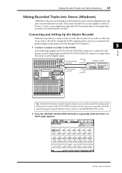
... master recorder's digital input, and the 01V96 2TR IN DIGITAL connector is the process of the master recorder to the 01V96. Mixing Recorded Tracks into Stereo (Mixdown) 63 Mixing Recorded Tracks into Stereo (Mixdown) "Mixdown" is connected to the 01V96. Change the 01V96's internal patch so ...+4 GAIN -26 +4 GAIN -26 MONITOR OUT PEAK SIGNAL 13 PEAK SIGNAL 14 15 PEAK SIGNAL 16 0 LEVEL10 PHONES DISPLAY ACCESS SCENE MEMORY SCENE DIO/SETUP MIDI UTILITY / INSERT/ PAN/ PAIR/ DELAY ROUTING GROUP PATCH DYNAMICS EQ EFFECT FADER MODE VIEW AUX 1 AUX 2 AUX 3 AUX 4 AUX 5 AUX...
... master recorder's digital input, and the 01V96 2TR IN DIGITAL connector is the process of the master recorder to the 01V96. Mixing Recorded Tracks into Stereo (Mixdown) 63 Mixing Recorded Tracks into Stereo (Mixdown) "Mixdown" is connected to the 01V96. Change the 01V96's internal patch so ...+4 GAIN -26 +4 GAIN -26 MONITOR OUT PEAK SIGNAL 13 PEAK SIGNAL 14 15 PEAK SIGNAL 16 0 LEVEL10 PHONES DISPLAY ACCESS SCENE MEMORY SCENE DIO/SETUP MIDI UTILITY / INSERT/ PAN/ PAIR/ DELAY ROUTING GROUP PATCH DYNAMICS EQ EFFECT FADER MODE VIEW AUX 1 AUX 2 AUX 3 AUX 4 AUX 5 AUX...
Owner's Manual
Page 68
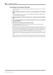
...the current mix settings to memory as the wordclock source. During recording, observe the stereo meter on the right of master recorder is input at the 01V96's 2TR IN DIGITAL connector, then routed through ST IN Channel 2 to the Stereo bus. The playback signal is connected to the... 01V96's 2TR IN DIGITAL connector, access the DIO/Setup | Word Clock page and select "2TRD" (2TR IN DIGITAL) as a Scene (see page 161). 01V96-Owner's Manual 68 Chapter 5-Tutorial Recording to the Master Recorder Follow the steps ...
...the current mix settings to memory as the wordclock source. During recording, observe the stereo meter on the right of master recorder is input at the 01V96's 2TR IN DIGITAL connector, then routed through ST IN Channel 2 to the Stereo bus. The playback signal is connected to the... 01V96's 2TR IN DIGITAL connector, access the DIO/Setup | Word Clock page and select "2TRD" (2TR IN DIGITAL) as a Scene (see page 161). 01V96-Owner's Manual 68 Chapter 5-Tutorial Recording to the Master Recorder Follow the steps ...
Owner's Manual
Page 72
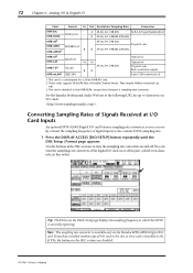
...MY4-DA 4 20-bit, 44.1/48 kHz XLR-3-32 type (balanced) x4 Analog out - You can easily convert the sampling frequency of digital inputs to turn the sampling rate converters of the digital I/O card on or off . If you can turn the sampling rate converters on the Word ...cards support 24-bit/96 kHz in the SRC sections to the current 01V96 sampling rate. 1 Press the DISPLAY ACCESS [DIO/SETUP] button repeatedly until the DIO/Setup | Format page appears. See the Yamaha Professional Audio Web site at which the 01V96 is a substitution for up-to the MY8-AE96, except that it features...
...MY4-DA 4 20-bit, 44.1/48 kHz XLR-3-32 type (balanced) x4 Analog out - You can easily convert the sampling frequency of digital inputs to turn the sampling rate converters of the digital I/O card on or off . If you can turn the sampling rate converters on the Word ...cards support 24-bit/96 kHz in the SRC sections to the current 01V96 sampling rate. 1 Press the DISPLAY ACCESS [DIO/SETUP] button repeatedly until the DIO/Setup | Format page appears. See the Yamaha Professional Audio Web site at which the 01V96 is a substitution for up-to the MY8-AE96, except that it features...
Owner's Manual
Page 75
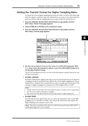
... in which the optional Yamaha MY8-AE96 or MY8-AE96S Digital I /O 4 Use the cursor buttons to move the cursor to an IN/OUT parameter field (1), then rotate the Parameter wheel or press the [INC]/[DEC] buttons to set one of inputs or outputs on the ...transmit or receive data. This is handled by the external devices. 1 Press the DISPLAY ACCESS [DIO/SETUP] button repeatedly until the DIO/Setup | Format page appears. 1 6 Analog I/O & Digital I /O card is installed. 01V96-Owner's Manual Note: • Double Channel mode reduces the total number of the following data transfer...
... in which the optional Yamaha MY8-AE96 or MY8-AE96S Digital I /O 4 Use the cursor buttons to move the cursor to an IN/OUT parameter field (1), then rotate the Parameter wheel or press the [INC]/[DEC] buttons to set one of inputs or outputs on the ...transmit or receive data. This is handled by the external devices. 1 Press the DISPLAY ACCESS [DIO/SETUP] button repeatedly until the DIO/Setup | Format page appears. 1 6 Analog I/O & Digital I /O card is installed. 01V96-Owner's Manual Note: • Double Channel mode reduces the total number of the following data transfer...
Owner's Manual
Page 86
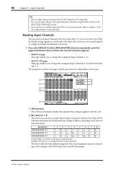
...ST IN Channels L & R separately. • You can also adjust the pan setting for the Input Channels using the PAN control in the SELECTED CHANNEL section. • Surround Pan is available when the 01V96 is in Surround mode. ROUT17-ST1 page This page enables you can route each... 17-32 and ST IN Channels 1-4. The actual assignment may vary, depending on the settings on the DIO/Setup | Surround Bus Setup page. 01V96-Owner's Manual Routing Input Channels You can patch signals to the Bus outs. With the default setting, signals are the same. 1 5 6 2 7 3 4 8 A PAN buttons These ...
...ST IN Channels L & R separately. • You can also adjust the pan setting for the Input Channels using the PAN control in the SELECTED CHANNEL section. • Surround Pan is available when the 01V96 is in Surround mode. ROUT17-ST1 page This page enables you can route each... 17-32 and ST IN Channels 1-4. The actual assignment may vary, depending on the settings on the DIO/Setup | Surround Bus Setup page. 01V96-Owner's Manual Routing Input Channels You can patch signals to the Bus outs. With the default setting, signals are the same. 1 5 6 2 7 3 4 8 A PAN buttons These ...
Owner's Manual
Page 132
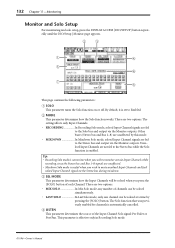
...01V96-Owner's Manual There are two options. There are two options. • MIX SOLO In Mix Solo mode, any number of channels can be soloed simultaneously. • LAST SOLO In Last Solo mode, only one channel can be soloed when you wish to monitor certain Input.... The Solo function that was previously enabled for channels is enabled. 132 Chapter 11-Monitoring Monitor and Solo Setup For monitoring and solo setup, press the DISPLAY ACCESS [DIO/SETUP] button repeatedly until the DIO/Setup | Monitor page appears. 2 3 1 4 5 6 7 8 This page contains the following parameters: A SOLO ...
...01V96-Owner's Manual There are two options. There are two options. • MIX SOLO In Mix Solo mode, any number of channels can be soloed simultaneously. • LAST SOLO In Last Solo mode, only one channel can be soloed when you wish to monitor certain Input.... The Solo function that was previously enabled for channels is enabled. 132 Chapter 11-Monitoring Monitor and Solo Setup For monitoring and solo setup, press the DISPLAY ACCESS [DIO/SETUP] button repeatedly until the DIO/Setup | Monitor page appears. 2 3 1 4 5 6 7 8 This page contains the following parameters: A SOLO ...


