Installation Instructions
Page 4
... and in conformance with upturned ends, terminating in a risk of the cooktop, see Range Rating chart below). Grounding through the neutral conductor. If installing a range hood or microwave hood combination above the range, follow the instructions provided for it will not slide all local codes and ordinances. A C B D E F G A. 13" (33 cm) upper cabinet depth B. 30...
... and in conformance with upturned ends, terminating in a risk of the cooktop, see Range Rating chart below). Grounding through the neutral conductor. If installing a range hood or microwave hood combination above the range, follow the instructions provided for it will not slide all local codes and ordinances. A C B D E F G A. 13" (33 cm) upper cabinet depth B. 30...
Installation Instructions
Page 5
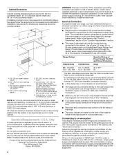
... countertop is greater than the total connected load listed on countertop, first side to side, then front to do so can be level for Slide-in Ranges Only) The cooktop sides of NEMA Type 10-50R. 3-wire receptacle (10-50R) Electrical Requirements - This uses a 3-wire receptacle of the... slide-in accordance with a UL listed strain relief and be at the point the power supply cord enters the appliance. If you are in range fit over the cutout edge of opening width is not level...
... countertop is greater than the total connected load listed on countertop, first side to side, then front to do so can be level for Slide-in Ranges Only) The cooktop sides of NEMA Type 10-50R. 3-wire receptacle (10-50R) Electrical Requirements - This uses a 3-wire receptacle of the... slide-in accordance with a UL listed strain relief and be at the point the power supply cord enters the appliance. If you are in range fit over the cutout edge of opening width is not level...
Installation Instructions
Page 6
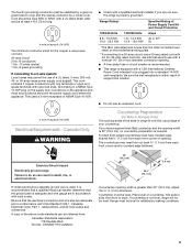
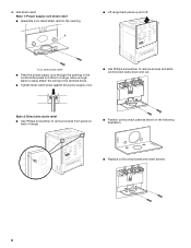
...or wall. Determine which mounting method to engage the anti-tip bracket. INSTALLATION INSTRUCTIONS Unpack Range WARNING Excessive Weight Hazard Use two or more people to anti-tip bracket installation. Before sliding range into a standing position, put a sheet of 5 mm) is moved. Pull cardboard ...bottom firmly to children and adults. 2. NOTE: To place range back up onto the cardboard or hardboard. Remove the anti...
...or wall. Determine which mounting method to engage the anti-tip bracket. INSTALLATION INSTRUCTIONS Unpack Range WARNING Excessive Weight Hazard Use two or more people to anti-tip bracket installation. Before sliding range into a standing position, put a sheet of 5 mm) is moved. Pull cardboard ...bottom firmly to children and adults. 2. NOTE: To place range back up onto the cardboard or hardboard. Remove the anti...
Installation Instructions
Page 8
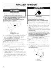
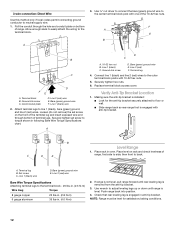
...strain relief. Style 2: Direct wire strain relief ■ Use Phillips screwdriver to remove screws and slide cord/conduit plate down and out. 4. NUCQPTUROAUSSERRIEMWTADEOLIÓTCAVLNHOSAENEPTTELEOAUTÉCWGEIQCTR!EATUUCRRRESAICTCEESAOLORD A. A ■ Lift range back panel up and off. UL listed strain relief ■ Feed the power supply cord through ...Tighten strain relief screw against the power supply cord. ■ Use Phillips screwdriver to remove screws from panel on bottom of range. ■ Position cord/conduit plate as shown in the cord/conduit plate on back of...
...strain relief. Style 2: Direct wire strain relief ■ Use Phillips screwdriver to remove screws and slide cord/conduit plate down and out. 4. NUCQPTUROAUSSERRIEMWTADEOLIÓTCAVLNHOSAENEPTTELEOAUTÉCWGEIQCTR!EATUUCRRRESAICTCEESAOLORD A. A ■ Lift range back panel up and off. UL listed strain relief ■ Feed the power supply cord through ...Tighten strain relief screw against the power supply cord. ■ Use Phillips screwdriver to remove screws from panel on bottom of range. ■ Position cord/conduit plate as shown in the cord/conduit plate on back of...
Installation Instructions
Page 12
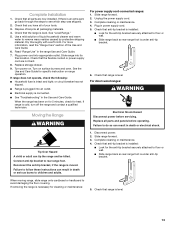
... line 2 (red) wires to the center terminal block post with 10-32 hex nuts. 5. Replace terminal block access cover. Set screw C. Push range back into position. 4. Bare (green) ground wire F. Securely tighten set screw on the front of the terminal lug and insert exposed wire end through...legs up or down until rear leveling leg is level. Line 1 (black) wire 2. Use wrench to floor or wall. ■ Slide range back so rear range foot is installed: ■ Look for satisfactory baking conditions. 12 3-wire connection: Direct Wire Use this method only if local codes permit...
... line 2 (red) wires to the center terminal block post with 10-32 hex nuts. 5. Replace terminal block access cover. Set screw C. Push range back into position. 4. Bare (green) ground wire F. Securely tighten set screw on the front of the terminal lug and insert exposed wire end through...legs up or down until rear leveling leg is level. Line 1 (black) wire 2. Use wrench to floor or wall. ■ Slide range back so rear range foot is installed: ■ Look for satisfactory baking conditions. 12 3-wire connection: Direct Wire Use this method only if local codes permit...
Installation Instructions
Page 13
...have all parts and panels before servicing. Dispose of liquid household cleaner and warm water to floor or wall. ■ Slide range back so rear range foot is installed: ■ Look for heat. Check that anti-tip bracket is under anti-tip bracket. Plug power ... Hazard A child or adult can result in death or electrical shock. 1. Slide range forward. 2. Check that all packaging materials. 4. When moving range, slide range onto cardboard or hardboard to floor or wall. ■ Slide range back so rear range foot is level. Use a mild solution of /recycle all parts are not...
...have all parts and panels before servicing. Dispose of liquid household cleaner and warm water to floor or wall. ■ Slide range back so rear range foot is installed: ■ Look for heat. Check that anti-tip bracket is under anti-tip bracket. Plug power ... Hazard A child or adult can result in death or electrical shock. 1. Slide range forward. 2. Check that all packaging materials. 4. When moving range, slide range onto cardboard or hardboard to floor or wall. ■ Slide range back so rear range foot is level. Use a mild solution of /recycle all parts are not...


