Installation Instructions
Page 1
... use above electric or gas cooking products up to Wall 9 Install the Microwave Oven 9 Complete Installation 10 VENTING DESIGN SPECIFICATIONS 11 ASSISTANCE 12 Replacement Parts 12 MICROWAVE HOOD COMBINATION SAFETY Your safety and the safety of Contents... Tools and Parts 2 Location Requirements 2 Product Dimensions 3 Electrical Requirements 3 INSTALLATION INSTRUCTIONS 4 Wall Venting Installation Only 4 Install Damper Assembly (for wall venting only 4 Roof Venting Installation Only 4 Install Damper Assembly (for further notes. This symbol alerts you to potential hazards ...
... use above electric or gas cooking products up to Wall 9 Install the Microwave Oven 9 Complete Installation 10 VENTING DESIGN SPECIFICATIONS 11 ASSISTANCE 12 Replacement Parts 12 MICROWAVE HOOD COMBINATION SAFETY Your safety and the safety of Contents... Tools and Parts 2 Location Requirements 2 Product Dimensions 3 Electrical Requirements 3 INSTALLATION INSTRUCTIONS 4 Wall Venting Installation Only 4 Install Damper Assembly (for wall venting only 4 Roof Venting Installation Only 4 Install Damper Assembly (for further notes. This symbol alerts you to potential hazards ...
Installation Instructions
Page 2
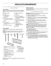
...items placed inside the microwave oven and upper cabinet. ■■ Grounded electrical outlet inside upper cabinet. Special Requirements For Wall Venting Installation Only: ■■ Cutout must provide: ■■ Minimum installation dimensions. Read and follow the instructions provided with... withstand the heat produced by the microwave oven for cooking. NOTE: Some cabinet and building materials are for wall or ro venting) J. For Roof Venting Installation Only: ■■ If you are using a rectangular-to-round transition piece, the 3" (7.6 cm) clearance needs...
...items placed inside the microwave oven and upper cabinet. ■■ Grounded electrical outlet inside upper cabinet. Special Requirements For Wall Venting Installation Only: ■■ Cutout must provide: ■■ Minimum installation dimensions. Read and follow the instructions provided with... withstand the heat produced by the microwave oven for cooking. NOTE: Some cabinet and building materials are for wall or ro venting) J. For Roof Venting Installation Only: ■■ If you are using a rectangular-to-round transition piece, the 3" (7.6 cm) clearance needs...
Installation Instructions
Page 3
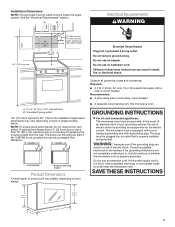
...than 14" (35.6 cm) but can result in death, fire, or electrical shock. NOTE: To ensure good performance, do not obstruct top vent airflow. If cabinets are not completely understood, or if doubt exists as to follow these instructions can result in a risk of electric shock by...a qualified electrician or serviceman install an outlet near the microwave oven. Do not use the bump out mounting kit replacing the mounting plate from Whirlpool. 12" DEEPER 14" 14" DEEPER 15" mounting plate Bump out mounting bracket Product Dimensions *Overall depth of product will vary slightly depending ...
...than 14" (35.6 cm) but can result in death, fire, or electrical shock. NOTE: To ensure good performance, do not obstruct top vent airflow. If cabinets are not completely understood, or if doubt exists as to follow these instructions can result in a risk of electric shock by...a qualified electrician or serviceman install an outlet near the microwave oven. Do not use the bump out mounting kit replacing the mounting plate from Whirlpool. 12" DEEPER 14" 14" DEEPER 15" mounting plate Bump out mounting bracket Product Dimensions *Overall depth of product will vary slightly depending ...
Installation Instructions
Page 4
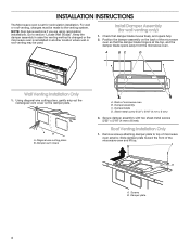
...Check that the damper blade hinge is at the top, and the damper blade opens away from the microwave oven. A BC D Wall Venting Installation Only 1. Damper vent covers A. Back of microwave oven exterior. Secure damper assembly with two sheet metal screws 5/32" x 5/16" (4 mm x 8 mm...). Remove screws attaching damper plate to top of microwave oven B. Screws B. Using diagonal wire cutting pliers, gently snip out the rectangular vent cover on the back of the microwave oven and lift up. Sheet metal screw 5/32" x 5/16" (4 mm x 8 mm) 3. Slide damper plate ...
...Check that the damper blade hinge is at the top, and the damper blade opens away from the microwave oven. A BC D Wall Venting Installation Only 1. Damper vent covers A. Back of microwave oven exterior. Secure damper assembly with two sheet metal screws 5/32" x 5/16" (4 mm x 8 mm...). Remove screws attaching damper plate to top of microwave oven B. Screws B. Using diagonal wire cutting pliers, gently snip out the rectangular vent cover on the back of the microwave oven and lift up. Sheet metal screw 5/32" x 5/16" (4 mm x 8 mm) 3. Slide damper plate ...
Installation Instructions
Page 5
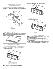
...lighting cover 3. Take J from step 1. Top of each stud and draw a plumb line down each stud center. Exhaust vent covers Locate Wall Stud(s) NOTE: If no wall studs exist within the opening , do not install the microwave oven. ...Screws B. Secure damper assembly with screw removed from packaging upper foam (see item J in "Parts Supplied" section), attach both wall and upper vent installation) 1. Keep C for future recirculation vent installation. 5 B C B A. Install Damper Assembly (for both of microwave oven so that damper blade moves freely, and opens fully. ...
...lighting cover 3. Take J from step 1. Top of each stud and draw a plumb line down each stud center. Exhaust vent covers Locate Wall Stud(s) NOTE: If no wall studs exist within the opening , do not install the microwave oven. ...Screws B. Secure damper assembly with screw removed from packaging upper foam (see item J in "Parts Supplied" section), attach both wall and upper vent installation) 1. Keep C for future recirculation vent installation. 5 B C B A. Install Damper Assembly (for both of microwave oven so that damper blade moves freely, and opens fully. ...
Installation Instructions
Page 6
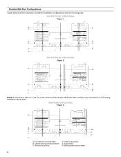
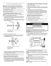
... F. Cabinet opening vertical centerline C. Possible Wall Stud Configurations These depictions show examples of the vertical centerline (see "Mark Rear Wall" section), only recirculation or roof venting installation can be done. No Wall Studs at End Holes Figure 1 B C C D D A A REAR WALL REAR WALL E E F No Wall Studs at End Holes Figure 3 B D A A,D E REAR WALL REAR...
... F. Cabinet opening vertical centerline C. Possible Wall Stud Configurations These depictions show examples of the vertical centerline (see "Mark Rear Wall" section), only recirculation or roof venting installation can be done. No Wall Studs at End Holes Figure 1 B C C D D A A REAR WALL REAR WALL E E F No Wall Studs at End Holes Figure 3 B D A A,D E REAR WALL REAR...
Installation Instructions
Page 8
... end holes are 3 installation configurations. Drill a 5/8" (1.6 cm) hole through the wall at the other end hole. Installation for BACK WALL Venting A2 B1 B2 Drill Holes in Step 3 of cabinet D. Make sure it is leveled and top of the mounting plate is leveled with front... wall stud, preferably 2, using a minimum of "Mark Rear Wall." Installation for No Wall Studs at One End Hole (Figure 3) 1. Roof Venting Installation Only If venting through the roof, mark and trace the corner punches on the back wall. Rear wall B. Installation for Wall Stud at End Holes (Figures 1 ...
... end holes are 3 installation configurations. Drill a 5/8" (1.6 cm) hole through the wall at the other end hole. Installation for BACK WALL Venting A2 B1 B2 Drill Holes in Step 3 of cabinet D. Make sure it is leveled and top of the mounting plate is leveled with front... wall stud, preferably 2, using a minimum of "Mark Rear Wall." Installation for No Wall Studs at One End Hole (Figure 3) 1. Roof Venting Installation Only If venting through the roof, mark and trace the corner punches on the back wall. Rear wall B. Installation for Wall Stud at End Holes (Figures 1 ...
Installation Instructions
Page 9
... heavy side. Insert lag screw(s) into the hole(s) drilled into both ends. 1. Push microwave oven against drywall. 2. For fast wall and roof vent installation, see the quick reference guide on at least 1 wall stud as well as at Both End Holes (Figure 4) 1. Failure to make sure... toggle nuts have opened against drywall. 5. Mounting plate C. NOTE: If venting through the end hole that fits over the 5/8" (1.6 cm) hole drilled in Step 2 of the mounting plate. Install the Microwave Oven WARNING Excessive Weight...
... heavy side. Insert lag screw(s) into the hole(s) drilled into both ends. 1. Push microwave oven against drywall. 2. For fast wall and roof vent installation, see the quick reference guide on at least 1 wall stud as well as at Both End Holes (Figure 4) 1. Failure to make sure... toggle nuts have opened against drywall. 5. Mounting plate C. NOTE: If venting through the end hole that fits over the 5/8" (1.6 cm) hole drilled in Step 2 of the mounting plate. Install the Microwave Oven WARNING Excessive Weight...
Installation Instructions
Page 10
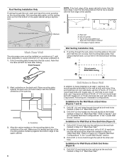
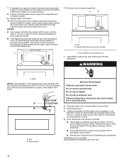
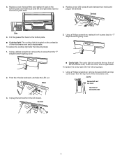
...B. Repeat steps 3 through upper cabinet into a grounded 3 prong outlet. ■■ See the User Instructions for filter placement. A B A. Vent B. Mounting Nut Electrical Shock Hazard Plug into grounded 3 prong outlet. 3. Do not use . 10 Check the operation of microwave oven by operating the... vent fan. 5. Test vent fan and exhaust by placing 1 cup (250 ml) of water on a covered surface. 8. If the problem continues, call an electrician...
...B. Repeat steps 3 through upper cabinet into a grounded 3 prong outlet. ■■ See the User Instructions for filter placement. A B A. Vent B. Mounting Nut Electrical Shock Hazard Plug into grounded 3 prong outlet. 3. Do not use . 10 Check the operation of microwave oven by operating the... vent fan. 5. Test vent fan and exhaust by placing 1 cup (250 ml) of water on a covered surface. 8. If the problem continues, call an electrician...
Installation Instructions
Page 11
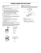
...there is proper clearance within walls or ceilings, attics, crawl spaces, or garages. diameter round vent C. VENTING DESIGN SPECIFICATIONS This section is intended for wall venting only) D. If venting through the wall, be sure there are not provided with microwave hood combination. ■■ ...) of clearance between the top of elbows to provide efficient performance ■■ Using uniformly sized vents ■■ Using duct tape to seal all joints in the vent system ■■ Using caulking compound to seal exterior wall or roof opening around cap ■&#...
...there is proper clearance within walls or ceilings, attics, crawl spaces, or garages. diameter round vent C. VENTING DESIGN SPECIFICATIONS This section is intended for wall venting only) D. If venting through the wall, be sure there are not provided with microwave hood combination. ■■ ...) of clearance between the top of elbows to provide efficient performance ■■ Using uniformly sized vents ■■ Using duct tape to seal all joints in the vent system ■■ Using caulking compound to seal exterior wall or roof opening around cap ■&#...
Installation Instructions
Page 12
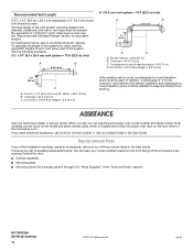
...° elbow = 25 ft (7.6 m) B. 1 wall cap = 40 ft (12.2 m) C. 2 ft (0.6 m) + 6 ft (1.8 m) straight = 8 ft (2.4 m) If the existing vent is a list of the vent system including straight vent, elbow(s), transitions, and wall or roof caps must be installed to -round transition piece must be used. Following is round, a rectangular-to...service center. To calculate the length of the microwave oven. See the following examples. 3¹⁄4" x 10" (8.3 x 25.4 cm) vent system = 73 ft (22.2 m) total. Both numbers can be found on the model and serial number plate, which is located behind ...
...° elbow = 25 ft (7.6 m) B. 1 wall cap = 40 ft (12.2 m) C. 2 ft (0.6 m) + 6 ft (1.8 m) straight = 8 ft (2.4 m) If the existing vent is a list of the vent system including straight vent, elbow(s), transitions, and wall or roof caps must be installed to -round transition piece must be used. Following is round, a rectangular-to...service center. To calculate the length of the microwave oven. See the following examples. 3¹⁄4" x 10" (8.3 x 25.4 cm) vent system = 73 ft (22.2 m) total. Both numbers can be found on the model and serial number plate, which is located behind ...
Owners Manual
Page 2
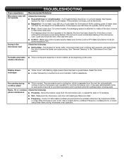
... authorized service company for a short time before removing the container. - After heating, allow soil or cleaner residue to facilitate cooking. I Use care when cleaning the vent-hood filter. Corrosive cleaning agents, such as water, coffee, or tea are placed inside the oven ignite, keep oven door closed, turn the fan on...
... authorized service company for a short time before removing the container. - After heating, allow soil or cleaner residue to facilitate cooking. I Use care when cleaning the vent-hood filter. Corrosive cleaning agents, such as water, coffee, or tea are placed inside the oven ignite, keep oven door closed, turn the fan on...
Owners Manual
Page 3
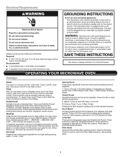
...the grounding instructions are three available speeds HIGH--->MEDIUM--->MEDIUM LOW-LOW--->OFF. Touch and hold the Cancel keypad for High setting. Vent Fan Press the Vent Fan keypad once for about 3 seconds until 2 tones sound and the CONTROL LOCKED appears in the display. To keep the ...To cancel timer, touch Timer control while the Timer countdown is too short, have two options. Choose the speed you want. Vent Light Pressing Vent Light keypad adjusts the vent light setting among HIGH -> LOW -> OFF. Scroll Speed Scrolling speed options will save . If the power supply cord is ...
...the grounding instructions are three available speeds HIGH--->MEDIUM--->MEDIUM LOW-LOW--->OFF. Touch and hold the Cancel keypad for High setting. Vent Fan Press the Vent Fan keypad once for about 3 seconds until 2 tones sound and the CONTROL LOCKED appears in the display. To keep the ...To cancel timer, touch Timer control while the Timer countdown is too short, have two options. Choose the speed you want. Vent Light Pressing Vent Light keypad adjusts the vent light setting among HIGH -> LOW -> OFF. Scroll Speed Scrolling speed options will save . If the power supply cord is ...
Owners Manual
Page 4
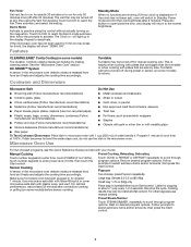
...stays cool, do not use manual cooking. Microwave Oven Use For list of preset programs, see the Quick Reference Guide provided with plastic wrap, and vent. Follow prompts to activate. Large bag: Senses 3.0-3.5 oz (85-99g) Small bag: 1.75 oz (50g) only Place bag on some models) ...not 100%), touch number keypads to select submenu items and/or amounts, then press the Start control. 4 Touch CLOCK to practice using the Vent Fan keypad. Program 1 minute of water beside it. Rest on desired program options. Demo Mode Activate to reach the Fan Timer submenu and ...
...stays cool, do not use manual cooking. Microwave Oven Use For list of preset programs, see the Quick Reference Guide provided with plastic wrap, and vent. Follow prompts to activate. Large bag: Senses 3.0-3.5 oz (85-99g) Small bag: 1.75 oz (50g) only Place bag on some models) ...not 100%), touch number keypads to select submenu items and/or amounts, then press the Start control. 4 Touch CLOCK to practice using the Vent Fan keypad. Program 1 minute of water beside it. Rest on desired program options. Demo Mode Activate to reach the Fan Timer submenu and ...
Owners Manual
Page 5
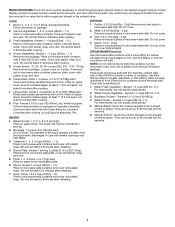
...3. Stir and let stand 2-3minutes after cooking. 4. Do not cover. 3. STEAM/SIMMER (sensor): Use microwave-safe container with plastic wrap, and vent. Add 2-4 tbs (30-60mL) water. Stir and let stand 2-3minutes after reheating. The diameter of food. Soup: Sense 1,2,3,4 cups (250mL ...-1L) Place in microwave-safe container and cover with plastic wrap, and vent. 5. Steam Fresh Vegetable - Senses 1-4 cups (250 mL-1 L): For best results, cut into equally sized pieces. 5. Manual Simmer: Touch the...
...3. Stir and let stand 2-3minutes after cooking. 4. Do not cover. 3. STEAM/SIMMER (sensor): Use microwave-safe container with plastic wrap, and vent. Add 2-4 tbs (30-60mL) water. Stir and let stand 2-3minutes after reheating. The diameter of food. Soup: Sense 1,2,3,4 cups (250mL ...-1L) Place in microwave-safe container and cover with plastic wrap, and vent. 5. Steam Fresh Vegetable - Senses 1-4 cups (250 mL-1 L): For best results, cut into equally sized pieces. 5. Manual Simmer: Touch the...
Owners Manual
Page 7
... refer the following steps: 1. Unplug the terminal from the "T" shaped bottom lighting cover. 5. Using a Phillips screwdriver, remove the second left vent top cover Top front of the microwave oven. Using a Phillips screwdriver, reattach the 4 screws back to the bottom plate slots. 4. Screw Second left... vent top cover screw from the top front of micowave oven 7 Terminal ■■ Cavity light: The cavity light is located at the...
... refer the following steps: 1. Unplug the terminal from the "T" shaped bottom lighting cover. 5. Using a Phillips screwdriver, remove the second left vent top cover Top front of the microwave oven. Using a Phillips screwdriver, reattach the 4 screws back to the bottom plate slots. 4. Screw Second left... vent top cover screw from the top front of micowave oven 7 Terminal ■■ Cavity light: The cavity light is located at the...
Owners Manual
Page 8
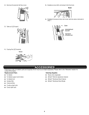
... with the screw removed in step 1. Screw Second left top cover. 3. Terminal 5. Remove the second left vent top cover Top front of micowave oven ACCESSORIES Following is a list of available parts and supplies which may be purchased separately. Replacement Parts Cleaning Supplies &#...
... with the screw removed in step 1. Screw Second left top cover. 3. Terminal 5. Remove the second left vent top cover Top front of micowave oven ACCESSORIES Following is a list of available parts and supplies which may be purchased separately. Replacement Parts Cleaning Supplies &#...
Owners Manual
Page 9
... oven's cooling fan, which is attached to avoid unintended starting of the door, remove it, then firmly close door. Move the receiver away from the vent fan, automatically comes on cavity walls, microwave inlet cover, cooking rack supports, and area where the door touches the frame can cause arcing. If a household...
... oven's cooling fan, which is attached to avoid unintended starting of the door, remove it, then firmly close door. Move the receiver away from the vent fan, automatically comes on cavity walls, microwave inlet cover, cooking rack supports, and area where the door touches the frame can cause arcing. If a household...


