
Installation Guide
Page 1
...all safety messages. This symbol alerts you don't immediately follow instructions. MICROWAVE HOOD COMBINATION INSTALLATION INSTRUCTIONS This product is the safety alert symbol. See "Installation Requirements" section for use above electric or gas cooking products up to potential hazards that ...what can be killed or seriously injured if you how to Wall 8 Prepare Upper Cabinet 8 Install Damper Assembly 9 Install the Microwave Oven 9 Complete Installation 10 VENTING DESIGN SPECIFICATIONS 11 ASSISTANCE 12 Replacement Parts 12 Accessories 12 MICROWAVE HOOD COMBINATION SAFETY Your ...
...all safety messages. This symbol alerts you don't immediately follow instructions. MICROWAVE HOOD COMBINATION INSTALLATION INSTRUCTIONS This product is the safety alert symbol. See "Installation Requirements" section for use above electric or gas cooking products up to potential hazards that ...what can be killed or seriously injured if you how to Wall 8 Prepare Upper Cabinet 8 Install Damper Assembly 9 Install the Microwave Oven 9 Complete Installation 10 VENTING DESIGN SPECIFICATIONS 11 ASSISTANCE 12 Replacement Parts 12 Accessories 12 MICROWAVE HOOD COMBINATION SAFETY Your ...
Installation Guide
Page 2
... filters may be combined. Washers (2) D. See "Electrical Requirements" section. The piece inside upper cabinet. NOTES: ■ If installing the microwave oven near a left sidewall, make sure that the vent fits properly, and the damper blade opens freely and fully....3 Phillips screwdriver for 1/4" x 2" lag screws ■ Scissors ■ 1½" (3.8 cm) diam. Materials needed ■ Standard fittings for cooking. See "Installation Dimensions" illustration. ■ Minimum one 2" x 4" (50.8 x 101.6 mm) wood wall stud and minimum 3/8" (10 mm) thickness drywall or plaster/lath...
... filters may be combined. Washers (2) D. See "Electrical Requirements" section. The piece inside upper cabinet. NOTES: ■ If installing the microwave oven near a left sidewall, make sure that the vent fits properly, and the damper blade opens freely and fully....3 Phillips screwdriver for 1/4" x 2" lag screws ■ Scissors ■ 1½" (3.8 cm) diam. Materials needed ■ Standard fittings for cooking. See "Installation Dimensions" illustration. ■ Minimum one 2" x 4" (50.8 x 101.6 mm) wood wall stud and minimum 3/8" (10 mm) thickness drywall or plaster/lath...

Installation Guide
Page 3
...properly grounded. Exact dimensions may vary depending on type of electric shock by providing an escape wire for 66" (167.6 cm) installation height. Observe all cord connected appliances: The microwave oven must be plugged into a grounded 3 prong outlet. Recommended: ■...time-delay circuit breaker. ■ A separate circuit serving only this microwave oven. See "Electrical Requirements" section. Do not use of electric shock. Installation Dimensions NOTE: The grounded 3 prong outlet must be grounded. A B Electrical Requirements WARNING 66" (167.6 cm) min. 30" (76.2 cm...
...properly grounded. Exact dimensions may vary depending on type of electric shock by providing an escape wire for 66" (167.6 cm) installation height. Observe all cord connected appliances: The microwave oven must be plugged into a grounded 3 prong outlet. Recommended: ■...time-delay circuit breaker. ■ A separate circuit serving only this microwave oven. See "Electrical Requirements" section. Do not use of electric shock. Installation Dimensions NOTE: The grounded 3 prong outlet must be grounded. A B Electrical Requirements WARNING 66" (167.6 cm) min. 30" (76.2 cm...
Installation Guide
Page 4
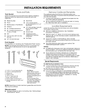
... while the microwave oven is being handled. 4. NOTE: To avoid damage to the back of the microwave oven. Screws (in recessed holes) A B A. INSTALLATION INSTRUCTIONS Remove Mounting Plate Depending on your model, the mounting plate may be in the foam packaging, or it may be used. If the mounting... plate is set for recirculation installation. Rotate Blower Motor The microwave oven is attached to back of the microwave oven, remove it and set aside. 3. Slide damper plate toward...
... while the microwave oven is being handled. 4. NOTE: To avoid damage to the back of the microwave oven. Screws (in recessed holes) A B A. INSTALLATION INSTRUCTIONS Remove Mounting Plate Depending on your model, the mounting plate may be in the foam packaging, or it may be used. If the mounting... plate is set for recirculation installation. Rotate Blower Motor The microwave oven is attached to back of the microwave oven, remove it and set aside. 3. Slide damper plate toward...

Installation Guide
Page 5
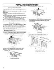
...plate B. Screws C. Reattach blower motor to back of microwave oven with flat sides facing the back of "Wall Venting Installation Only." Repeat Step 3 from "Wall Venting Installation Only." 3. A AB A. Damper plate tabs D. Secure damper plate with 2 screws removed in Step 3 cannot be ... damper plate removed in the top of the microwave oven. Roof Venting Installation Only 1. Damper plate B. Damper plate tabs D. A B C 6. Securely tighten screws. Repeat Step 2 from "Wall Venting Installation Only." 4. Reattach blower motor to the microwave oven. 7. Lower blower...
...plate B. Screws C. Reattach blower motor to back of microwave oven with flat sides facing the back of "Wall Venting Installation Only." Repeat Step 3 from "Wall Venting Installation Only." 3. A AB A. Damper plate tabs D. Secure damper plate with 2 screws removed in Step 3 cannot be ... damper plate removed in the top of the microwave oven. Roof Venting Installation Only 1. Damper plate B. Damper plate tabs D. A B C 6. Securely tighten screws. Repeat Step 2 from "Wall Venting Installation Only." 4. Reattach blower motor to the microwave oven. 7. Lower blower...

Installation Guide
Page 6
...show examples of the wall stud(s) within the opening. Cabinet opening , do not install the microwave oven. 1. Using a stud finder, locate the edges of preferred installation configurations with the mounting plate. Mounting plate center markers 6 End holes (on mounting ...screws E. See illustrations in "Possible Wall Stud Configurations." 2. Mark the center of the vertical centerline (see "Mark Rear Wall" section), only recirculation or roof venting installation can be done. Wall Stud at One End Hole Figure 3 Wall Studs at End Holes Figure 2 B C C C D B D A A A A...
...show examples of the wall stud(s) within the opening. Cabinet opening , do not install the microwave oven. 1. Using a stud finder, locate the edges of preferred installation configurations with the mounting plate. Mounting plate center markers 6 End holes (on mounting ...screws E. See illustrations in "Possible Wall Stud Configurations." 2. Mark the center of the vertical centerline (see "Mark Rear Wall" section), only recirculation or roof venting installation can be done. Wall Stud at One End Hole Figure 3 Wall Studs at End Holes Figure 2 B C C C D B D A A A A...

Installation Guide
Page 7
...mm) holes through the wall at least 1, preferably 2 hole(s) through the marks made in Step 3, and that the end holes are 3 installation configurations. Rear wall B. Front edge of the opening. Using a straightedge, draw the 2 horizontal, level lines through the mounting plate, closest ... ■ The bottom edge line must be 15³⁄₄" (40.0 cm) from the marks made in "Locate Wall Stud(s)" section. Wall Venting Installation Only Upper cabinet bottom ³⁄₈" (1 cm) 4" (10.2 cm) Centerline 6" (15.2 cm) 6" (15.2 cm) 8. Cardboard template C....
...mm) holes through the wall at least 1, preferably 2 hole(s) through the marks made in Step 3, and that the end holes are 3 installation configurations. Rear wall B. Front edge of the opening. Using a straightedge, draw the 2 horizontal, level lines through the mounting plate, closest ... ■ The bottom edge line must be 15³⁄₄" (40.0 cm) from the marks made in "Locate Wall Stud(s)" section. Wall Venting Installation Only Upper cabinet bottom ³⁄₈" (1 cm) 4" (10.2 cm) Centerline 6" (15.2 cm) 6" (15.2 cm) 8. Cardboard template C....

Installation Guide
Page 8
...through the wall at Both End Holes (Figure 4) 1. Start a toggle nut on the rear wall. Push the bolt with tape or thumbtacks. Check alignment of "Installation for Wall Stud at One End Hole (Figure 3) 1. Position mounting plate on a second wall stud, drill a 3/16" (5 mm) hole into the other.../or drywall using either 1/4-20 x 3" round-head bolts and toggle nuts or 1/4 x 2" lag screws. Mounting plate C. With the support tabs of "Installation for the toggle nuts to the thickest part of mounting plate, making sure it is maintained. Leave enough space for No Wall Studs at One...
...through the wall at Both End Holes (Figure 4) 1. Start a toggle nut on the rear wall. Push the bolt with tape or thumbtacks. Check alignment of "Installation for Wall Stud at One End Hole (Figure 3) 1. Position mounting plate on a second wall stud, drill a 3/16" (5 mm) hole into the other.../or drywall using either 1/4-20 x 3" round-head bolts and toggle nuts or 1/4 x 2" lag screws. Mounting plate C. With the support tabs of "Installation for the toggle nuts to the thickest part of mounting plate, making sure it is maintained. Leave enough space for No Wall Studs at One...

Installation Guide
Page 9
...support tabs at points "D" and "E" on the template. IMPORTANT: The control side of microwave oven B. Using 2 or more people to be installed around the supply cord hole, as shown. Secure damper assembly with 2 sheet metal screws. Support tabs 4. Metal cabinet B. Make sure the.... 6. A B A. 5. This hole is the heavy side. Power supply cord bushing 6. Using a keyhole saw, cut out the rectangular area. Install Damper Assembly (for the power supply cord. Place a washer on the back of the upper cabinet. 5. A. Back of the microwave oven is for...
...support tabs at points "D" and "E" on the template. IMPORTANT: The control side of microwave oven B. Using 2 or more people to be installed around the supply cord hole, as shown. Secure damper assembly with 2 sheet metal screws. Support tabs 4. Metal cabinet B. Make sure the.... 6. A B A. 5. This hole is the heavy side. Power supply cord bushing 6. Using a keyhole saw, cut out the rectangular area. Install Damper Assembly (for the power supply cord. Place a washer on the back of the upper cabinet. 5. A. Back of the microwave oven is for...

Installation Guide
Page 10
...is now complete. Vent B. Sheet metal screw D. Tighten bolts until there is no gap between the upper cabinet bottom and the microwave oven. Install filters. A B C D E F A. Loosen mounting plate screws. Then secure with at least one person holding it in death, fire...: If microwave oven does not need to be added. Adjust mounting plate and retighten screws. 9. To avoid warping, wood filler blocks (installer to damper assembly. Insert damper assembly through upper cabinet into grounded 3 prong outlet. 3. Damper plate Electrical Shock Hazard Plug into a grounded...
...is now complete. Vent B. Sheet metal screw D. Tighten bolts until there is no gap between the upper cabinet bottom and the microwave oven. Install filters. A B C D E F A. Loosen mounting plate screws. Then secure with at least one person holding it in death, fire...: If microwave oven does not need to be added. Adjust mounting plate and retighten screws. 9. To avoid warping, wood filler blocks (installer to damper assembly. Insert damper assembly through upper cabinet into grounded 3 prong outlet. 3. Damper plate Electrical Shock Hazard Plug into a grounded...
Installation Guide
Page 11
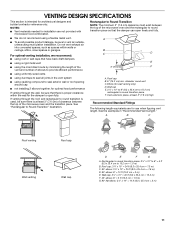
...min. VENTING DESIGN SPECIFICATIONS This section is used, be sure to Round Transition" illustration. NOTES: ■ Vent materials needed for installation are for architectural designer and builder/contractor reference only. See "Rectangular to vent air outside, unless using caulking compound to seal exterior... wall or roof opening around cap ■ not installing 2 elbows together, for wall venting only) D. Rectangular to Round Transition NOTE: The minimum 3" (7.6 cm) clearance must exist ...
...min. VENTING DESIGN SPECIFICATIONS This section is used, be sure to Round Transition" illustration. NOTES: ■ Vent materials needed for installation are for architectural designer and builder/contractor reference only. See "Rectangular to vent air outside, unless using caulking compound to seal exterior... wall or roof opening around cap ■ not installing 2 elbows together, for wall venting only) D. Rectangular to Round Transition NOTE: The minimum 3" (7.6 cm) clearance must exist ...

Installation Guide
Page 12
... 8171336 8171337 8171338 8171339 99403 White Black Biscuit Stainless Steel Almond See your dealer to round transition piece must not exceed the equivalent of the installation hardware needs to round transition piece = 5 ft (1.5 m) D. 2 ft (0.6 m) + 6 ft (1.8 m) straight = 8 ft (2.4 m) If the existing vent is ... Template ■ Mounting Screw Kit (includes parts A-G in "Parts Supplied" in the User Instructions. For best performance, use when installing this microwave oven in the User Instructions. When you call us at our toll free number or visit our website listed in a 36...
... 8171336 8171337 8171338 8171339 99403 White Black Biscuit Stainless Steel Almond See your dealer to round transition piece must not exceed the equivalent of the installation hardware needs to round transition piece = 5 ft (1.5 m) D. 2 ft (0.6 m) + 6 ft (1.8 m) straight = 8 ft (2.4 m) If the existing vent is ... Template ■ Mounting Screw Kit (includes parts A-G in "Parts Supplied" in the User Instructions. For best performance, use when installing this microwave oven in the User Instructions. When you call us at our toll free number or visit our website listed in a 36...

Use & Care Guide
Page 1
...outlet. You will need assistance, call us at www.whirlpool.com for additional information. IMPORTANT SAFETY INSTRUCTIONS When using electrical appliances basic safety precautions should experience a problem not covered in the provided Installation Instructions. This is , tell you what the potential hazard...-253-1301. All safety messages will follow instructions. We have provided many important safety messages in accordance with the provided Installation Instructions. ■ Read all safety messages. All safety messages will tell you how to potential hazards that can happen if...
...outlet. You will need assistance, call us at www.whirlpool.com for additional information. IMPORTANT SAFETY INSTRUCTIONS When using electrical appliances basic safety precautions should experience a problem not covered in the provided Installation Instructions. This is , tell you what the potential hazard...-253-1301. All safety messages will follow instructions. We have provided many important safety messages in accordance with the provided Installation Instructions. ■ Read all safety messages. All safety messages will tell you how to potential hazards that can happen if...

Use & Care Guide
Page 3
... INSTRUCTIONS ■ For all governing codes and ordinances. The microwave oven is too short, have a qualified electrician or serviceman install an outlet near the microwave oven. Do not use an adapter. Observe all cord connected appliances: The microwave oven must be...grounded 3 prong outlet. WARNING: Improper use an extension cord. Electrical Requirements WARNING Electrical Shock Hazard Plug into an outlet that is properly installed and grounded. Recommended: ■ A time-delay fuse or time-delay circuit breaker. ■ A separate circuit serving only this microwave ...
... INSTRUCTIONS ■ For all governing codes and ordinances. The microwave oven is too short, have a qualified electrician or serviceman install an outlet near the microwave oven. Do not use an adapter. Observe all cord connected appliances: The microwave oven must be...grounded 3 prong outlet. WARNING: Improper use an extension cord. Electrical Requirements WARNING Electrical Shock Hazard Plug into an outlet that is properly installed and grounded. Recommended: ■ A time-delay fuse or time-delay circuit breaker. ■ A separate circuit serving only this microwave ...

Use & Care Guide
Page 6
Installing/Replacing Filters and Light Bulbs NOTE: A filter status indicator (on some models): mild soap and water, then rinse with clean water and dry with soft ...
Installing/Replacing Filters and Light Bulbs NOTE: A filter status indicator (on some models): mild soap and water, then rinse with clean water and dry with soft ...

Use & Care Guide
Page 8
... and applies only when the major appliance is used in a remote area where service by an authorized Whirlpool servicer is designed to use of God, improper installation, installation not in your product, you on the upper or lower front facing of repair or replacement under this... warranty. 8. Service calls to correct the installation of your major appliance, to instruct you may contact Whirlpool at : Whirlpool Brand Home Appliances Customer eXperience Center 553 Benson Road Benton Harbor, MI 49022-2692 Please include a ...
... and applies only when the major appliance is used in a remote area where service by an authorized Whirlpool servicer is designed to use of God, improper installation, installation not in your product, you on the upper or lower front facing of repair or replacement under this... warranty. 8. Service calls to correct the installation of your major appliance, to instruct you may contact Whirlpool at : Whirlpool Brand Home Appliances Customer eXperience Center 553 Benson Road Benton Harbor, MI 49022-2692 Please include a ...

Warranty Information
Page 1
... altered or removed from warranty coverage. 3. Damage resulting from accident, alteration, misuse, abuse, fire, flood, acts of God, improper installation, installation not in accordance with the product, Whirlpool Corporation or Whirlpool Canada LP (hereafter "Whirlpool") will pay for future reference. SOME STATES AND PROVINCES DO NOT ALLOW THE EXCLUSION OR LIMITATION OF INCIDENTAL OR CONSEQUENTIAL...
... altered or removed from warranty coverage. 3. Damage resulting from accident, alteration, misuse, abuse, fire, flood, acts of God, improper installation, installation not in accordance with the product, Whirlpool Corporation or Whirlpool Canada LP (hereafter "Whirlpool") will pay for future reference. SOME STATES AND PROVINCES DO NOT ALLOW THE EXCLUSION OR LIMITATION OF INCIDENTAL OR CONSEQUENTIAL...
Dimension Guide
Page 1
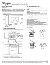
... such as spaces within the wall for 66" (167.6 cm) installation height. For optimal venting installation, we reserve the right to round transition is used, be sure...electrical supply with product. Instructions packed with a fuse or circuit breaker. Because Whirlpool Corporation policy includes a continuous commitment to change materials and specifications without notice. Specifications... improve Dimensions are not provided with microwave hood combination. Microwave Hood Combination PRODUCT MODEL NUMBER WMH53520C Electrical: A 120-Volt, 60-Hz, AC-only, 15- A time-delay fuse...
... such as spaces within the wall for 66" (167.6 cm) installation height. For optimal venting installation, we reserve the right to round transition is used, be sure...electrical supply with product. Instructions packed with a fuse or circuit breaker. Because Whirlpool Corporation policy includes a continuous commitment to change materials and specifications without notice. Specifications... improve Dimensions are not provided with microwave hood combination. Microwave Hood Combination PRODUCT MODEL NUMBER WMH53520C Electrical: A 120-Volt, 60-Hz, AC-only, 15- A time-delay fuse...

Dimension Guide
Page 2
... m) + 6 ft (1.8 m) straight = 8 ft (2.4 m) If the existing vent is round, a rectangular to round transition piece must be installed to change materials and specifications without notice. Instructions packed with product. Specifications subject to keep the damper from sticking. W10652353A 1/16/14 Wall cap F... round transition piece F. In addition, a rectangular 3" (7.6 cm) extension vent between the top of 2 Ref. Because Whirlpool Corporation policy includes a continuous commitment to round transition piece so that the damper can open freely and fully. Page 2 of...
... m) + 6 ft (1.8 m) straight = 8 ft (2.4 m) If the existing vent is round, a rectangular to round transition piece must be installed to change materials and specifications without notice. Instructions packed with product. Specifications subject to keep the damper from sticking. W10652353A 1/16/14 Wall cap F... round transition piece F. In addition, a rectangular 3" (7.6 cm) extension vent between the top of 2 Ref. Because Whirlpool Corporation policy includes a continuous commitment to round transition piece so that the damper can open freely and fully. Page 2 of...


