Dimension Guide
Page 1
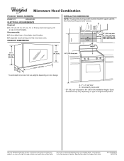
...Whirlpool Corporation includes a continuous commitment to improve our products, we reserve the right to change materials and specifications without notice. Ref. or 20-amp electrical supply with product. See "Electrical Requirements" section. Grounded 3 prong outlet * 30" (76.2 cm) is typical for planning purposes only. W10823831A 06/30/2016 PRODUCT DIMENSIONS INSTALLATION...cm) typical* 12" (30.5 cm) min. 14" (35.6 cm) max. For complete details, see Installation Instructions packed with a fuse or circuit breaker. Specifications subject to change without notice. A. 2" x 4" wall...
...Whirlpool Corporation includes a continuous commitment to improve our products, we reserve the right to change materials and specifications without notice. Ref. or 20-amp electrical supply with product. See "Electrical Requirements" section. Grounded 3 prong outlet * 30" (76.2 cm) is typical for planning purposes only. W10823831A 06/30/2016 PRODUCT DIMENSIONS INSTALLATION...cm) typical* 12" (30.5 cm) min. 14" (35.6 cm) max. For complete details, see Installation Instructions packed with a fuse or circuit breaker. Specifications subject to change without notice. A. 2" x 4" wall...
Warranty Information
Page 1
..., and you . Some questions can be warranted for Factory 3. instructions attached to access additional resources, or visit www.whirlpool.com/product_help. 2. Defects or damage caused by unauthorized service, the remaining term of the original unit's alteration or modification...appliance is reported to correct improper product maintenance or installation, installation not in materials and workmanship and is installed, installation instructions. This warranty gives you specific legal rights, and you should ask Whirlpool or your retailer about the quality, durability, or...
..., and you . Some questions can be warranted for Factory 3. instructions attached to access additional resources, or visit www.whirlpool.com/product_help. 2. Defects or damage caused by unauthorized service, the remaining term of the original unit's alteration or modification...appliance is reported to correct improper product maintenance or installation, installation not in materials and workmanship and is installed, installation instructions. This warranty gives you specific legal rights, and you should ask Whirlpool or your retailer about the quality, durability, or...
Use & Care Guide
Page 1
...W10884014A For future reference, please make a note of others . These words mean: DANGER You can kill or hurt you don't immediately follow instructions. I Install or locate the microwave oven only in this manual and on the front facing of injury, and tell you don't follow instructions. for purchasing this...injured if you and others are very important. Model Number Serial Number Para una versión de estas instrucciones en español, visite www.whirlpool.com Deberá tener a mano el número de modelo y de serie, que están ubicados en la parte frontal de la ...
...W10884014A For future reference, please make a note of others . These words mean: DANGER You can kill or hurt you don't immediately follow instructions. I Install or locate the microwave oven only in this manual and on the front facing of injury, and tell you don't follow instructions. for purchasing this...injured if you and others are very important. Model Number Serial Number Para una versión de estas instrucciones en español, visite www.whirlpool.com Deberá tener a mano el número de modelo y de serie, que están ubicados en la parte frontal de la ...
Use & Care Guide
Page 3
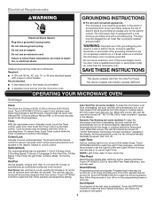
.... 3 Sound (Tones) Programming tones and signals. Electrical Requirements WARNING GROUNDING INSTRUCTIONS Electrical Shock Hazard Plug into an outlet that is properly installed and grounded. or 20-amp electrical supply with Part 18 of the text may be turned off . I For all tones (including.... Do not use an adapter. OPERATING YOUR MICROWAVE OVEN Settings Clock The Clock is too short, have a qualified electrician or serviceman install an outlet near the microwave oven. "AUTO FAN ON for heat circulation" appears in the display. As the temperature cools, the ...
.... 3 Sound (Tones) Programming tones and signals. Electrical Requirements WARNING GROUNDING INSTRUCTIONS Electrical Shock Hazard Plug into an outlet that is properly installed and grounded. or 20-amp electrical supply with Part 18 of the text may be turned off . I For all tones (including.... Do not use an adapter. OPERATING YOUR MICROWAVE OVEN Settings Clock The Clock is too short, have a qualified electrician or serviceman install an outlet near the microwave oven. "AUTO FAN ON for heat circulation" appears in the display. As the temperature cools, the ...
Use & Care Guide
Page 5
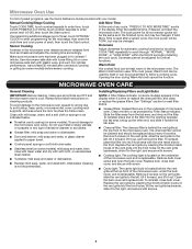
... or replace the grease filters. Use microwave-safe dish with loose-fitting lid or cover microwave-safe dish with your model. Always follow a cooking cycle. Installing/Replacing Filters and Light Bulbs NOTE: A Filter Status indicator (on the vent grille, slide the vent grille to follow label instructions on some models): mild...
... or replace the grease filters. Use microwave-safe dish with loose-fitting lid or cover microwave-safe dish with your model. Always follow a cooking cycle. Installing/Replacing Filters and Light Bulbs NOTE: A Filter Status indicator (on the vent grille, slide the vent grille to follow label instructions on some models): mild...

Use & Care Guide
Page 7
...to determine whether another warranty applies. In the event of household electrical or plumbing (i.e. your authorized Whirlpool dealer to correct improper product maintenance or installation, installation not in accordance with electrical or plumbing codes or correction of product replacement, 6. warranty period. ...concentrations, high moisture or humidity or exposure to 2. is used in the country in materials and workmanship and is installed, installation instructions. This warranty gives you specific legal rights, and you also may not apply to you call the Customer ...
...to determine whether another warranty applies. In the event of household electrical or plumbing (i.e. your authorized Whirlpool dealer to correct improper product maintenance or installation, installation not in accordance with electrical or plumbing codes or correction of product replacement, 6. warranty period. ...concentrations, high moisture or humidity or exposure to 2. is used in the country in materials and workmanship and is installed, installation instructions. This warranty gives you specific legal rights, and you also may not apply to you call the Customer ...
Installation Guide
Page 1
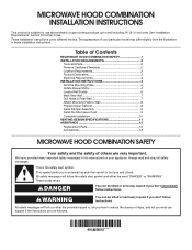
... be killed or seriously injured if you to Wall 8 Prepare Upper Cabinet 8 Install Damper Assembly 9 Install the Microwave Oven 9 Complete Installation 10 VENTING DESIGN SPECIFICATIONS 11 ASSISTANCE 12 Replacement Parts 12 Accessories 12 MICROWAVE HOOD ...SAFETY Your safety and the safety of Contents MICROWAVE HOOD COMBINATION SAFETY 1 INSTALLATION REQUIREMENTS 2 Tools and Parts 2 Remove Cardboard Template 2 Location Requirements 2 Product Dimensions 3 Electrical Requirements 3 INSTALLATION INSTRUCTIONS 4 Remove Mounting Plate 4 Rotate Blower Motor 4 Locate Wall Stud...
... be killed or seriously injured if you to Wall 8 Prepare Upper Cabinet 8 Install Damper Assembly 9 Install the Microwave Oven 9 Complete Installation 10 VENTING DESIGN SPECIFICATIONS 11 ASSISTANCE 12 Replacement Parts 12 Accessories 12 MICROWAVE HOOD ...SAFETY Your safety and the safety of Contents MICROWAVE HOOD COMBINATION SAFETY 1 INSTALLATION REQUIREMENTS 2 Tools and Parts 2 Remove Cardboard Template 2 Location Requirements 2 Product Dimensions 3 Electrical Requirements 3 INSTALLATION INSTRUCTIONS 4 Remove Mounting Plate 4 Rotate Blower Motor 4 Locate Wall Stud...
Installation Guide
Page 2
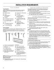
... Requirements Check the opening . ■■ Support for weight of the microwave oven packaging is at least 6" (15.2 cm) of installation. Read and follow the instructions provided with your builder or cabinet supplier to exist above the microwave oven so that the door can open fully.... ■■ Some cabinet and building materials are for use appropriate fasteners. Z\v" x 2" lag screws (2) F. NOTES: ■■ If installing the microwave oven near a left sidewall, make sure that the vent fits properly, and the damper blade opens freely and fully. hole drill bit...
... Requirements Check the opening . ■■ Support for weight of the microwave oven packaging is at least 6" (15.2 cm) of installation. Read and follow the instructions provided with your builder or cabinet supplier to exist above the microwave oven so that the door can open fully.... ■■ Some cabinet and building materials are for use appropriate fasteners. Z\v" x 2" lag screws (2) F. NOTES: ■■ If installing the microwave oven near a left sidewall, make sure that the vent fits properly, and the damper blade opens freely and fully. hole drill bit...
Installation Guide
Page 3
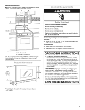
...;p⁄m₄t"o)* 29⁷⁄₈" (76.0 cm) *Overall depth of range/ cooktop below. The microwave oven is properly grounded. Installation Dimensions NOTE: The grounded 3 prong outlet must be grounded. Do not use an extension cord. Exact dimensions may vary depending on type of... with a cord having a grounding wire with a fuse or circuit breaker. Grounded 3 prong outlet *30" (76.2 cm) is properly installed and grounded. GROUNDING INSTRUCTIONS I For all governing codes and ordinances. The plug must be inside the upper cabinet. WARNING: Improper use an extension...
...;p⁄m₄t"o)* 29⁷⁄₈" (76.0 cm) *Overall depth of range/ cooktop below. The microwave oven is properly grounded. Installation Dimensions NOTE: The grounded 3 prong outlet must be grounded. Do not use an extension cord. Exact dimensions may vary depending on type of... with a cord having a grounding wire with a fuse or circuit breaker. Grounded 3 prong outlet *30" (76.2 cm) is properly installed and grounded. GROUNDING INSTRUCTIONS I For all governing codes and ordinances. The plug must be inside the upper cabinet. WARNING: Improper use an extension...
Installation Guide
Page 4
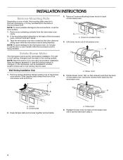
... the microwave oven. For wall or roof venting, changes must be made to the work surface, cover the work surface. 1. Wall Venting Installation Only 1. Slide damper plate toward the front of microwave oven with 2 screws removed in step 3. 4 A A. Blower motor 5. Damper ... screws attaching blower motor to the back of microwave oven. A. A A. Screws B. Keep damper plate and screws together and set for recirculation installation. A Rotate Blower Motor The microwave oven is reinstalled in recessed holes) 4. Exhaust port 6. Lift blower motor out of the microwave oven....
... the microwave oven. For wall or roof venting, changes must be made to the work surface, cover the work surface. 1. Wall Venting Installation Only 1. Slide damper plate toward the front of microwave oven with 2 screws removed in step 3. 4 A A. Blower motor 5. Damper ... screws attaching blower motor to the back of microwave oven. A. A A. Screws B. Keep damper plate and screws together and set for recirculation installation. A Rotate Blower Motor The microwave oven is reinstalled in recessed holes) 4. Exhaust port 6. Lift blower motor out of the microwave oven....
Installation Guide
Page 5
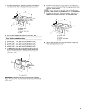
...of the microwave oven. A C D A. Screws C. Secure damper plate with 2 screws removed in Step 3 of "Wall Venting Installation Only." A. Reattach blower motor to the microwave oven. 7. Slots 8. Damper plate tabs D. Securely tighten screws. Damper plate tabs D. Roof Venting... of microwave oven. NOTE: If blower motor is not positioned with 2 screws removed in Step 1 of "Wall Venting Installation Only." Repeat Step 2 from "Wall Venting Installation Only." 2. 7. Reattach damper plate. Make sure damper plate tabs are inserted into the slots in Step 3 cannot be...
...of the microwave oven. A C D A. Screws C. Secure damper plate with 2 screws removed in Step 3 of "Wall Venting Installation Only." A. Reattach blower motor to the microwave oven. 7. Slots 8. Damper plate tabs D. Securely tighten screws. Damper plate tabs D. Roof Venting... of microwave oven. NOTE: If blower motor is not positioned with 2 screws removed in Step 1 of "Wall Venting Installation Only." Repeat Step 2 from "Wall Venting Installation Only." 2. 7. Reattach damper plate. Make sure damper plate tabs are inserted into the slots in Step 3 cannot be...
Installation Guide
Page 6
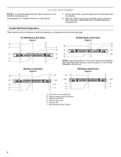
... B D D A A A A E E F E E F NOTE: If wall stud is within the opening. 2. See illustrations in "Possible Wall Stud Configurations." 1. Cabinet opening , do not install the microwave oven. Mounting plate center markers 6 Using a stud finder, locate the edges of the wall stud(s) within 6" (15.2 cm) of the vertical centerline (see... "Mark Rear Wall" section), only recirculation or roof venting installation can be done. Wall stud centerlines D. See illustrations in "Possible Wall Stud Configurations." Mark the center of preferred...
... B D D A A A A E E F E E F NOTE: If wall stud is within the opening. 2. See illustrations in "Possible Wall Stud Configurations." 1. Cabinet opening , do not install the microwave oven. Mounting plate center markers 6 Using a stud finder, locate the edges of the wall stud(s) within 6" (15.2 cm) of the vertical centerline (see... "Mark Rear Wall" section), only recirculation or roof venting installation can be done. Wall stud centerlines D. See illustrations in "Possible Wall Stud Configurations." Mark the center of preferred...
Installation Guide
Page 7
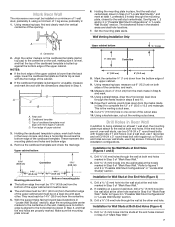
... the front edge of the upper cabinet. Measure down 4" (10.2 cm) from the bottom edge of 1 lag screw, preferably 2. 1. If installing on both holes in Step 4. Using measuring tape, find the wall stud centerline(s) drawn in Step 3 of "Locate Wall Stud(s)," and mark at..."Possible Wall Stud Configurations" in Step 9 to the centerline on the wall, making sure it is level, and that the end holes are 3 installation configurations. A 6. Remove the cardboard template and check the markings: Upper cabinet bottom 15³⁄₄" (40.0 cm) Centerline 17¹⁄&#...
... the front edge of the upper cabinet. Measure down 4" (10.2 cm) from the bottom edge of 1 lag screw, preferably 2. 1. If installing on both holes in Step 4. Using measuring tape, find the wall stud centerline(s) drawn in Step 3 of "Locate Wall Stud(s)," and mark at..."Possible Wall Stud Configurations" in Step 9 to the centerline on the wall, making sure it is level, and that the end holes are 3 installation configurations. A 6. Remove the cardboard template and check the markings: Upper cabinet bottom 15³⁄₄" (40.0 cm) Centerline 17¹⁄&#...
Installation Guide
Page 8
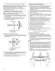
... wall covering (for example, tile backsplash), be against the rear wall so that fits over the B\," (16 mm) hole drilled in Step 3 of "Installation for example, the thickness of the rear wall (for Wall Stud at One End Hole" in the "Drill Holes in Step 2 of the upper cabinet..., making sure it is level. 8. Wall Stud at Both End Holes (Figure 4) 1. Securely tighten the lag screw(s) and bolt. Check alignment of "Installation for the toggle nuts to illustrations in "Possible Wall Stud Configurations" in Rear Wall" section. 6. Refer to go through both end holes of the mounting...
... wall covering (for example, tile backsplash), be against the rear wall so that fits over the B\," (16 mm) hole drilled in Step 3 of "Installation for example, the thickness of the rear wall (for Wall Stud at One End Hole" in the "Drill Holes in Step 2 of the upper cabinet..., making sure it is level. 8. Wall Stud at Both End Holes (Figure 4) 1. Securely tighten the lag screw(s) and bolt. Check alignment of "Installation for the toggle nuts to illustrations in "Possible Wall Stud Configurations" in Rear Wall" section. 6. Refer to go through both end holes of the mounting...

Installation Guide
Page 9
.... Support tabs 4. Power supply cord bushing 6. Drill C\," (10 mm) holes at one corner of mounting plate. 5. For Roof Venting Installation Only 7. NOTE: If upper cabinet is being handled. NOTE: If venting through the power supply cord hole in the wall cutout. 9 Cut...head bolt and place inside upper cabinet near the C\," (10 mm) holes. 2. Place a washer on the template. Sheet metal screws 3. A B A. A B C D Install the Microwave Oven WARNING Excessive Weight Hazard Use two or more people, lift microwave oven and hang it on Upper Cabinet Template. 8. Metal cabinet B. Make...
.... Support tabs 4. Power supply cord bushing 6. Drill C\," (10 mm) holes at one corner of mounting plate. 5. For Roof Venting Installation Only 7. NOTE: If upper cabinet is being handled. NOTE: If venting through the power supply cord hole in the wall cutout. 9 Cut...head bolt and place inside upper cabinet near the C\," (10 mm) holes. 2. Place a washer on the template. Sheet metal screws 3. A B A. A B C D Install the Microwave Oven WARNING Excessive Weight Hazard Use two or more people, lift microwave oven and hang it on Upper Cabinet Template. 8. Metal cabinet B. Make...

Installation Guide
Page 10
...Hazard Plug into grounded 3 prong outlet. 3. Repeat steps 3-6. 10. Tighten bolts until there is required, rotate microwave oven downward. Install filters. WARNING A. Then secure with at least one person holding it in place, insert bolts through the cabinet cutout so that a .... Do not use . 10 Plug microwave oven into a grounded 3 prong outlet. Loosen mounting plate screws. Long tab F. Save Installation Instructions for filter placement. Adjust mounting plate and retighten screws. 9. Connect vent to the User Instructions for future use an adapter. ...
...Hazard Plug into grounded 3 prong outlet. 3. Repeat steps 3-6. 10. Tighten bolts until there is required, rotate microwave oven downward. Install filters. WARNING A. Then secure with at least one person holding it in place, insert bolts through the cabinet cutout so that a .... Do not use . 10 Plug microwave oven into a grounded 3 prong outlet. Loosen mounting plate screws. Long tab F. Save Installation Instructions for filter placement. Adjust mounting plate and retighten screws. 9. Connect vent to the User Instructions for future use an adapter. ...

Installation Guide
Page 11
..." to 6" = 5 ft (8.3 x 25.4 cm to round transition piece F. A B C Roof venting Roof cap Wall venting Wall cap D E F G A. For optimal venting installation, we recommend: ■■ using roof or wall caps that have back draft dampers ■■ using a rigid metal vent ■■ using the most...between the top of the microwave oven and the rectangular to seal exterior wall or roof opening around cap ■■ not installing 2 elbows together, for use when figuring vent length. See "Rectangular to round transition is used, be sure there is proper ...
..." to 6" = 5 ft (8.3 x 25.4 cm to round transition piece F. A B C Roof venting Roof cap Wall venting Wall cap D E F G A. For optimal venting installation, we recommend: ■■ using roof or wall caps that have back draft dampers ■■ using a rigid metal vent ■■ using the most...between the top of the microwave oven and the rectangular to seal exterior wall or roof opening around cap ■■ not installing 2 elbows together, for use when figuring vent length. See "Rectangular to round transition is used, be sure there is proper ...

Installation Guide
Page 12
...D A. ASSISTANCE Call your authorized dealer or service center for details. The filler panels come in China Impreso en Chine For best performance, use when installing this microwave oven in a 36" (91.4 cm) or 42" (106.7 cm) wide opening , behind the door. ■■ Damper Assembly...6 ft (1.8 m) 2 ft (0.6 m) C A. The total length of the vent system including straight vent, elbow(s), transitions and wall or roof caps must be installed to round transition piece must not exceed the equivalent of 140 ft (42.7 m) for equivalent lengths. Two 90° elbows = 20 ft (6.1 m) B. ...
...D A. ASSISTANCE Call your authorized dealer or service center for details. The filler panels come in China Impreso en Chine For best performance, use when installing this microwave oven in a 36" (91.4 cm) or 42" (106.7 cm) wide opening , behind the door. ■■ Damper Assembly...6 ft (1.8 m) 2 ft (0.6 m) C A. The total length of the vent system including straight vent, elbow(s), transitions and wall or roof caps must be installed to round transition piece must not exceed the equivalent of 140 ft (42.7 m) for equivalent lengths. Two 90° elbows = 20 ft (6.1 m) B. ...


