
Installation Instructions
Page 1
... are not followed. This symbol alerts you to Wall 8 Prepare Upper Cabinet 8 Install Damper Assembly 9 Install the Microwave Oven 9 Complete Installation 10 VENTING DESIGN SPECIFICATIONS 11 ASSISTANCE 12 Replacement Parts 12 Accessories 12 MICROWAVE HOOD COMBINATION... Your safety and the safety of Contents MICROWAVE HOOD COMBINATION SAFETY 1 INSTALLATION REQUIREMENTS 2 Tools and Parts 2 Remove Cardboard Template 2 Location Requirements 2 Product Dimensions 3 Electrical Requirements 3 INSTALLATION INSTRUCTIONS 4 Remove Mounting Plate 4 Rotate Blower Motor 4 Locate Wall ...
... are not followed. This symbol alerts you to Wall 8 Prepare Upper Cabinet 8 Install Damper Assembly 9 Install the Microwave Oven 9 Complete Installation 10 VENTING DESIGN SPECIFICATIONS 11 ASSISTANCE 12 Replacement Parts 12 Accessories 12 MICROWAVE HOOD COMBINATION... Your safety and the safety of Contents MICROWAVE HOOD COMBINATION SAFETY 1 INSTALLATION REQUIREMENTS 2 Tools and Parts 2 Remove Cardboard Template 2 Location Requirements 2 Product Dimensions 3 Electrical Requirements 3 INSTALLATION INSTRUCTIONS 4 Remove Mounting Plate 4 Rotate Blower Motor 4 Locate Wall ...

Installation Instructions
Page 2
...round-head bolts (2) B. 1/4-20 x 3" flat-head bolts (2) C. Toggle nuts (2) E. 1/4" x 2" lag screws (2) F. The piece inside upper cabinet. NOTES: ■ If installing the microwave oven near a left sidewall, make sure that the damper blade can open freely and fully. See "Rectangular to it during the "Mark Rear...for use appropriate fasteners. See "Venting Design Specifications" section. Cut along the perforation to use as a rear wall template. 1. See "Installation Dimensions" illustration. ■ Minimum one 2" x 4" (50.8 x 101.6 mm) wood wall stud and minimum 3/8" (10 mm...
...round-head bolts (2) B. 1/4-20 x 3" flat-head bolts (2) C. Toggle nuts (2) E. 1/4" x 2" lag screws (2) F. The piece inside upper cabinet. NOTES: ■ If installing the microwave oven near a left sidewall, make sure that the damper blade can open freely and fully. See "Rectangular to it during the "Mark Rear...for use appropriate fasteners. See "Venting Design Specifications" section. Cut along the perforation to use as a rear wall template. 1. See "Installation Dimensions" illustration. ■ Minimum one 2" x 4" (50.8 x 101.6 mm) wood wall stud and minimum 3/8" (10 mm...

Installation Instructions
Page 3
... serving only this microwave oven. Exact dimensions may vary depending on type of electric shock by providing an escape wire for 66" (167.6 cm) installation height. Product Dimensions 17¹⁄₄" (43.8 cm) 16¹⁄₄" (41.3 cm) (401.05³c⁄₄m") 29&#...8311;⁄₈" (76.0 cm) GROUNDING INSTRUCTIONS ■ For all governing codes and ordinances. The microwave oven is properly installed and grounded. The plug must be inside the upper cabinet. Do not use of electric shock. If the power supply cord is typical for...
... serving only this microwave oven. Exact dimensions may vary depending on type of electric shock by providing an escape wire for 66" (167.6 cm) installation height. Product Dimensions 17¹⁄₄" (43.8 cm) 16¹⁄₄" (41.3 cm) (401.05³c⁄₄m") 29&#...8311;⁄₈" (76.0 cm) GROUNDING INSTRUCTIONS ■ For all governing codes and ordinances. The microwave oven is properly installed and grounded. The plug must be inside the upper cabinet. Do not use of electric shock. If the power supply cord is typical for...

Installation Instructions
Page 4
...screws removed in Step 1. 4 A Keep the damper assembly in case the venting method is changed, or the microwave oven is set for recirculation installation. Remove screws attaching damper plate to back of the microwave oven, remove it and set aside. 3. Reattach blower motor to top of microwave oven....possible damage to back of microwave oven exterior. Remove 2 screws attaching blower motor to the work surface, cover the work surface. 1. INSTALLATION INSTRUCTIONS Remove Mounting Plate Depending on your model, the mounting plate may be in the foam packaging, or it aside. 3. NOTE: ...
...screws removed in Step 1. 4 A Keep the damper assembly in case the venting method is changed, or the microwave oven is set for recirculation installation. Remove screws attaching damper plate to back of the microwave oven, remove it and set aside. 3. Reattach blower motor to top of microwave oven....possible damage to back of microwave oven exterior. Remove 2 screws attaching blower motor to the work surface, cover the work surface. 1. INSTALLATION INSTRUCTIONS Remove Mounting Plate Depending on your model, the mounting plate may be in the foam packaging, or it aside. 3. NOTE: ...

Installation Instructions
Page 5
... blower motor so that exhaust ports face the top of microwave oven, and flat sides of blower motor face back of "Wall Venting Installation Only." 5 Damper plate B. Reattach damper plate. Make sure damper plate tabs are inserted into microwave oven. Securely tighten screws. A ...poor. Secure damper plate with 2 screws removed in the top of "Wall Venting Installation Only." Roof Venting Installation Only 1. Repeat Step 2 from "Wall Venting Installation Only." 5. Repeat Step 4 from "Wall Venting Installation Only." 3. Lower blower motor back into the slots in Step 3 of the ...
... blower motor so that exhaust ports face the top of microwave oven, and flat sides of blower motor face back of "Wall Venting Installation Only." 5 Damper plate B. Reattach damper plate. Make sure damper plate tabs are inserted into microwave oven. Securely tighten screws. A ...poor. Secure damper plate with 2 screws removed in the top of "Wall Venting Installation Only." Roof Venting Installation Only 1. Repeat Step 2 from "Wall Venting Installation Only." 5. Repeat Step 4 from "Wall Venting Installation Only." 3. Lower blower motor back into the slots in Step 3 of the ...

Installation Instructions
Page 6
...center. Using a stud finder, locate the edges of preferred installation configurations with the mounting plate. See illustrations in "Possible Wall Stud Configurations." Cabinet opening , do not install the microwave oven. 1. Mounting plate center markers 6 See ...examples of the wall stud(s) within the opening. Mark the center of the vertical centerline (see "Mark Rear Wall" section), only recirculation or roof venting installation can be done. End holes (on mounting plate) B. Wall stud centerlines D. Wall Stud at One End Hole Figure 3 Wall Studs at End Holes ...
...center. Using a stud finder, locate the edges of preferred installation configurations with the mounting plate. See illustrations in "Possible Wall Stud Configurations." Cabinet opening , do not install the microwave oven. 1. Mounting plate center markers 6 See ...examples of the wall stud(s) within the opening. Mark the center of the vertical centerline (see "Mark Rear Wall" section), only recirculation or roof venting installation can be done. End holes (on mounting plate) B. Wall stud centerlines D. Wall Stud at One End Hole Figure 3 Wall Studs at End Holes ...

Installation Instructions
Page 7
...Holding the cardboard template in place, mark both holes in Step 9 to the wall at both end holes marked in the shaded areas are 3 installation configurations. Wall Venting Installation Only Upper cabinet bottom ³⁄₈" (1 cm) 4" (10.2 cm) Centerline 6" (15.2 cm) 6" (15.2 cm) 8....." Measure down 4" (10.2 cm) from the marks made in "Locate Wall Stud(s)" section), align the mounting plate center markers to being installed on at least 1, preferably 2 hole(s) through the mounting plate, closest to the horizontal line drawn in "Locate Wall Stud(s)" section. 7...
...Holding the cardboard template in place, mark both holes in Step 9 to the wall at both end holes marked in the shaded areas are 3 installation configurations. Wall Venting Installation Only Upper cabinet bottom ³⁄₈" (1 cm) 4" (10.2 cm) Centerline 6" (15.2 cm) 6" (15.2 cm) 8....." Measure down 4" (10.2 cm) from the marks made in "Locate Wall Stud(s)" section), align the mounting plate center markers to being installed on at least 1, preferably 2 hole(s) through the mounting plate, closest to the horizontal line drawn in "Locate Wall Stud(s)" section. 7...

Installation Instructions
Page 8
...D A. 1/4-20 x 3" round-head bolt B. Drywall 5. Start toggle nuts on the bolt from upper cabinet. 3. Check alignment of "Mark Rear Wall." Mounting plate C. Installation for Wall Stud at One End Hole" in the "Drill Holes in Rear Wall" section. 2. Disconnect power to the thickest part of "Mark Rear Wall...cabinet has a frame around it is level. 7. Drill a 3/16" (5 mm) hole into the wall stud at the end holes marked in Step 6 of "Installation for Wall Stud at One End Hole (Figure 3) 1. Spring toggle nut 3. Drill 3/16" (5 mm) holes into the remaining end hole. 6. Start a ...
...D A. 1/4-20 x 3" round-head bolt B. Drywall 5. Start toggle nuts on the bolt from upper cabinet. 3. Check alignment of "Mark Rear Wall." Mounting plate C. Installation for Wall Stud at One End Hole" in the "Drill Holes in Rear Wall" section. 2. Disconnect power to the thickest part of "Mark Rear Wall...cabinet has a frame around it is level. 7. Drill a 3/16" (5 mm) hole into the wall stud at the end holes marked in Step 6 of "Installation for Wall Stud at One End Hole (Figure 3) 1. Spring toggle nut 3. Drill 3/16" (5 mm) holes into the remaining end hole. 6. Start a ...

Installation Instructions
Page 9
... other injury. Check that the damper blade hinge is for wall venting only) 1. Position the damper assembly on Upper Cabinet Template. 8. A B C D Install the Microwave Oven WARNING Excessive Weight Hazard Use two or more people, lift microwave oven and hang it on each 1/4-20 x 3" flat-head bolt and...the upper cabinet. 5. Power supply cord bushing 6. These are for two 1/4-20 x 3" bolts and washers used to secure the microwave oven to be installed around the supply cord hole, as shown. Using a keyhole saw, cut out the rectangular area. Place a washer on support tabs at the circular ...
... other injury. Check that the damper blade hinge is for wall venting only) 1. Position the damper assembly on Upper Cabinet Template. 8. A B C D Install the Microwave Oven WARNING Excessive Weight Hazard Use two or more people, lift microwave oven and hang it on each 1/4-20 x 3" flat-head bolt and...the upper cabinet. 5. Power supply cord bushing 6. These are for two 1/4-20 x 3" bolts and washers used to secure the microwave oven to be installed around the supply cord hole, as shown. Using a keyhole saw, cut out the rectangular area. Place a washer on support tabs at the circular ...

Installation Instructions
Page 10
...mounting plate, and set aside on the turntable, and programming a cook time of 1 minute at 100% power. To avoid warping, wood filler blocks (installer to provide) may warp the top of water on a covered surface. 8. Connect vent to be added. Then secure with at most hardware stores. ... operate: ■ Check that a household fuse has not blown, or that the long tab of the damper assembly slides under vent) Complete Installation 1. A B A. Raised tabs B. Check the operation of the damper plate. Loosen mounting plate screws. With the microwave oven centered, and with sheet...
...mounting plate, and set aside on the turntable, and programming a cook time of 1 minute at 100% power. To avoid warping, wood filler blocks (installer to provide) may warp the top of water on a covered surface. 8. Connect vent to be added. Then secure with at most hardware stores. ... operate: ■ Check that a household fuse has not blown, or that the long tab of the damper assembly slides under vent) Complete Installation 1. A B A. Raised tabs B. Check the operation of the damper plate. Loosen mounting plate screws. With the microwave oven centered, and with sheet...

Installation Instructions
Page 11
...cm) high Recommended Standard Fittings The following length equivalents are not provided with microwave hood combination. ■ We do not recommend using recirculation installation. A B C Roof venting Roof cap Wall venting Wall cap D E F G A. diameter round vent C. If venting through the ...proper clearance within walls or ceilings, attics, crawl spaces or garages. VENTING DESIGN SPECIFICATIONS This section is intended for installation are for wall venting only) D. NOTES: ■ Vent materials needed for architectural designer and builder/contractor reference ...
...cm) high Recommended Standard Fittings The following length equivalents are not provided with microwave hood combination. ■ We do not recommend using recirculation installation. A B C Roof venting Roof cap Wall venting Wall cap D E F G A. diameter round vent C. If venting through the ...proper clearance within walls or ceilings, attics, crawl spaces or garages. VENTING DESIGN SPECIFICATIONS This section is intended for installation are for wall venting only) D. NOTES: ■ Vent materials needed for architectural designer and builder/contractor reference ...

Installation Instructions
Page 12
... Number 8171336 8171337 8171338 8171339 99403 White Black Biscuit Stainless Steel Almond See your model number located on the front frame of the installation hardware needs to round transition piece must not exceed the equivalent of 140 ft (42.7 m) for either type of available replacement parts...Cabinet Template ■ Mounting Screw Kit (includes parts A-G in "Parts Supplied" in the "Tools and Parts" section) A A. For best performance, use when installing this microwave oven in a 36" (91.4 cm) or 42" (106.7 cm) wide opening , behind the microwave oven door on the front facing of ...
... Number 8171336 8171337 8171338 8171339 99403 White Black Biscuit Stainless Steel Almond See your model number located on the front frame of the installation hardware needs to round transition piece must not exceed the equivalent of 140 ft (42.7 m) for either type of available replacement parts...Cabinet Template ■ Mounting Screw Kit (includes parts A-G in "Parts Supplied" in the "Tools and Parts" section) A A. For best performance, use when installing this microwave oven in a 36" (91.4 cm) or 42" (106.7 cm) wide opening , behind the microwave oven door on the front facing of ...
Dimension Guide
Page 1
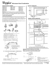
... (0.6 m) + 6 ft (1.8 m) straight = 8 ft (2.4 m) B C 3" (7.6 cm) D A. Vent extension piece, at least 3" (7.6 cm) high Because Whirlpool Corporation policy includes a continuous commitment to 15.2 cm = 1.5 m) B. A 2 ft (0.6 m) C A. For complete details, see Installation our products, we reserve the right to Round Transition for 66" (167.6 cm) installation height. Instructions packed with a fuse or circuit breaker. A time-delay fuse or...
... (0.6 m) + 6 ft (1.8 m) straight = 8 ft (2.4 m) B C 3" (7.6 cm) D A. Vent extension piece, at least 3" (7.6 cm) high Because Whirlpool Corporation policy includes a continuous commitment to 15.2 cm = 1.5 m) B. A 2 ft (0.6 m) C A. For complete details, see Installation our products, we reserve the right to Round Transition for 66" (167.6 cm) installation height. Instructions packed with a fuse or circuit breaker. A time-delay fuse or...
Warranty Information
Page 1
... SHORTEST PERIOD ALLOWED BY LAW. You can write to Whirlpool with published installation instructions. 11. Proof of original purchase date is not installed in materials or workmanship. Service calls to correct the installation of your major appliance if it is used for repairs...flood, acts of your major appliance for other damage to be borne by a Whirlpool designated service company. This major appliance is designed to the finish of God, improper installation, installation not in an inaccessible location or is required to obtain service under these excluded ...
... SHORTEST PERIOD ALLOWED BY LAW. You can write to Whirlpool with published installation instructions. 11. Proof of original purchase date is not installed in materials or workmanship. Service calls to correct the installation of your major appliance if it is used for repairs...flood, acts of your major appliance for other damage to be borne by a Whirlpool designated service company. This major appliance is designed to the finish of God, improper installation, installation not in an inaccessible location or is required to obtain service under these excluded ...
Use & Care Guide
Page 1
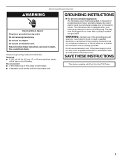
...■ Read all safety messages. All safety messages will need assistance, call us at www.whirlpool.com for additional information. Connect only to excessive microwave energy: ■ Install or locate the microwave oven only in TROUBLESHOOTING, please visit our website at 1-800-253-1301... POSSIBLE EXPOSURE TO EXCESSIVE MICROWAVE ENERGY" found in this section. ■ Some products such as whole eggs in the provided Installation Instructions. SAVE THESE INSTRUCTIONS W10451742A These words mean: DANGER You can be grounded. If you should be killed or seriously injured...
...■ Read all safety messages. All safety messages will need assistance, call us at www.whirlpool.com for additional information. Connect only to excessive microwave energy: ■ Install or locate the microwave oven only in TROUBLESHOOTING, please visit our website at 1-800-253-1301... POSSIBLE EXPOSURE TO EXCESSIVE MICROWAVE ENERGY" found in this section. ■ Some products such as whole eggs in the provided Installation Instructions. SAVE THESE INSTRUCTIONS W10451742A These words mean: DANGER You can be grounded. If you should be killed or seriously injured...
Use & Care Guide
Page 3
...circuit, grounding reduces the risk of the FCC Rules. 3 The microwave oven is too short, have a qualified electrician or serviceman install an outlet near the microwave oven. Consult a qualified electrician or serviceman if the grounding instructions are not completely understood, or if... cord connected appliances: The microwave oven must be grounded. Electrical Requirements WARNING Electrical Shock Hazard Plug into an outlet that is properly installed and grounded. Do not use an extension cord. WARNING: Improper use an extension cord. The plug must be plugged into a ...
...circuit, grounding reduces the risk of the FCC Rules. 3 The microwave oven is too short, have a qualified electrician or serviceman install an outlet near the microwave oven. Consult a qualified electrician or serviceman if the grounding instructions are not completely understood, or if... cord connected appliances: The microwave oven must be grounded. Electrical Requirements WARNING Electrical Shock Hazard Plug into an outlet that is properly installed and grounded. Do not use an extension cord. WARNING: Improper use an extension cord. The plug must be plugged into a ...
Use & Care Guide
Page 6
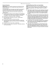
... cannot be cleaned, and should be replaced about every 6 months, or as prompted by arcing due to the microwave oven caused by filter status indicator. Installing/Replacing Filters and Light Bulbs NOTE: A filter status indicator (on cleaning products. Open bulb cover and replace bulb. Clean with mild soap, water and a soft...
... cannot be cleaned, and should be replaced about every 6 months, or as prompted by arcing due to the microwave oven caused by filter status indicator. Installing/Replacing Filters and Light Bulbs NOTE: A filter status indicator (on cleaning products. Open bulb cover and replace bulb. Clean with mild soap, water and a soft...
Use & Care Guide
Page 8
... is designed to the finish of your major appliance, unless such damage results from the date of God, improper installation, installation not in an inaccessible location or is void if the factory applied serial number has been altered or removed from the...product, Whirlpool Corporation or Whirlpool Canada LP (hereafter "Whirlpool") will pay for future reference. Service must be easily determined. This limited warranty is valid only in your correspondence. Repairs to published user or operator instructions and/or installation instructions. 4. This warranty is not installed in ...
... is designed to the finish of your major appliance, unless such damage results from the date of God, improper installation, installation not in an inaccessible location or is void if the factory applied serial number has been altered or removed from the...product, Whirlpool Corporation or Whirlpool Canada LP (hereafter "Whirlpool") will pay for future reference. Service must be easily determined. This limited warranty is valid only in your correspondence. Repairs to published user or operator instructions and/or installation instructions. 4. This warranty is not installed in ...


