
Installation Instructions
Page 1
See "Installation Requirements" section for use above electric or gas cooking products up to Wall 8 Prepare Upper Cabinet 8 Install Damper Assembly 9 Install the Microwave Oven 9 Complete Installation 10 VENTING DESIGN SPECIFICATIONS 11 ASSISTANCE 12 Replacement Parts 12 Accessories 12 MICROWAVE HOOD COMBINATION SAFETY Your safety and the safety of your appliance. This is the safety alert symbol. All safety messages will follow the safety alert symbol and either the word "DANGER" or "WARNING." WARNING You can be killed or seriously injured if you what can be ...
See "Installation Requirements" section for use above electric or gas cooking products up to Wall 8 Prepare Upper Cabinet 8 Install Damper Assembly 9 Install the Microwave Oven 9 Complete Installation 10 VENTING DESIGN SPECIFICATIONS 11 ASSISTANCE 12 Replacement Parts 12 Accessories 12 MICROWAVE HOOD COMBINATION SAFETY Your safety and the safety of your appliance. This is the safety alert symbol. All safety messages will follow the safety alert symbol and either the word "DANGER" or "WARNING." WARNING You can be killed or seriously injured if you what can be ...

Installation Instructions
Page 2
A B C D E FG H A. 1/4-20 x 3" round-head bolts (2) B. 1/4-20 x 3" flat-head bolts (2) C. Sheet metal screws (2) G. See "Venting Design Specifications" section. The piece inside upper cabinet. The location must be included. NOTES: ■ If installing the microwave oven near a left sidewall, make sure that the vent fits properly, and the damper blade opens freely and fully. Special Requirements For Wall Venting Installation Only: ■ Cutout must provide: ■ Minimum installation dimensions. Washers (2) D. Damper assembly (for weight of the microwave oven ...
A B C D E FG H A. 1/4-20 x 3" round-head bolts (2) B. 1/4-20 x 3" flat-head bolts (2) C. Sheet metal screws (2) G. See "Venting Design Specifications" section. The piece inside upper cabinet. The location must be included. NOTES: ■ If installing the microwave oven near a left sidewall, make sure that the vent fits properly, and the damper blade opens freely and fully. Special Requirements For Wall Venting Installation Only: ■ Cutout must provide: ■ Minimum installation dimensions. Washers (2) D. Damper assembly (for weight of the microwave oven ...

Installation Instructions
Page 3
Installation Dimensions NOTE: The grounded 3 prong outlet must be plugged into a grounded 3 prong outlet. See "Electrical Requirements" section. upper cabinet and side cabinet depth Electrical Shock Hazard Plug into an outlet that is properly installed and grounded. Required: ■ A 120 Volt, 60 Hz, AC only, 15- A. 2" x 4" wall stud B. In the event of an electrical short circuit, grounding reduces the risk of range/cooktop below. The microwave oven is properly grounded. The plug must be grounded. If the power supply cord is typical for the electric current. Do not remove ...
Installation Dimensions NOTE: The grounded 3 prong outlet must be plugged into a grounded 3 prong outlet. See "Electrical Requirements" section. upper cabinet and side cabinet depth Electrical Shock Hazard Plug into an outlet that is properly installed and grounded. Required: ■ A 120 Volt, 60 Hz, AC only, 15- A. 2" x 4" wall stud B. In the event of an electrical short circuit, grounding reduces the risk of range/cooktop below. The microwave oven is properly grounded. The plug must be grounded. If the power supply cord is typical for the electric current. Do not remove ...

Installation Instructions
Page 4
Remove any remaining contents from the microwave oven cavity. 2. A A. Reattach blower motor to top of microwave oven. Reattach damper plate. Damper plate 2. Damper plate B. NOTE: To avoid possible damage to the venting system. Lift blower motor out of the microwave oven and lift up. NOTE: Skip this section if you are inserted into the microwave oven. Slide damper plate toward the front of microwave oven. A A. Slots 8. Blower motor 5. Remove screws attaching damper plate to back of microwave oven with 2 screws removed in Step 1. 4 Screws C. For wall...
Remove any remaining contents from the microwave oven cavity. 2. A A. Reattach blower motor to top of microwave oven. Reattach damper plate. Damper plate 2. Damper plate B. NOTE: To avoid possible damage to the venting system. Lift blower motor out of the microwave oven and lift up. NOTE: Skip this section if you are inserted into the microwave oven. Slide damper plate toward the front of microwave oven. A A. Slots 8. Blower motor 5. Remove screws attaching damper plate to back of microwave oven with 2 screws removed in Step 1. 4 Screws C. For wall...

Installation Instructions
Page 5
Rotate blower motor so that exhaust ports face the top of microwave oven, and flat sides of blower motor face back of the microwave oven. Lower blower motor back into the slots in Step 1 of "Wall Venting Installation Only." A B C A. Damper plate tabs D. Repeat Step 2 from "Wall Venting Installation Only." 5. NOTE: If blower motor is not positioned with flat sides facing the back of the microwave oven (as shown), performance will be reattached to back of microwave oven with 2 screws removed in the top of microwave oven. Repeat Step 4 from "Wall Venting ...
Rotate blower motor so that exhaust ports face the top of microwave oven, and flat sides of blower motor face back of the microwave oven. Lower blower motor back into the slots in Step 1 of "Wall Venting Installation Only." A B C A. Damper plate tabs D. Repeat Step 2 from "Wall Venting Installation Only." 5. NOTE: If blower motor is not positioned with flat sides facing the back of the microwave oven (as shown), performance will be reattached to back of microwave oven with 2 screws removed in the top of microwave oven. Repeat Step 4 from "Wall Venting ...

Installation Instructions
Page 6
Wall stud centerlines D. See illustrations in "Possible Wall Stud Configurations." Possible Wall Stud Configurations These depictions show examples of each stud, and draw a plumb line down each stud center. Cabinet opening vertical centerline C. Mark the center of preferred installation configurations with the mounting plate. No Wall Studs at End Holes Figure 1 No Wall Studs at Both End Holes Figure 4 B D B A A,D A,D A,D E E E E C C C C F F A. Mounting plate center markers 6 Wall Stud at One End Hole Figure 3 Wall Studs at End Holes Figure 2 B C...
Wall stud centerlines D. See illustrations in "Possible Wall Stud Configurations." Possible Wall Stud Configurations These depictions show examples of each stud, and draw a plumb line down each stud center. Cabinet opening vertical centerline C. Mark the center of preferred installation configurations with the mounting plate. No Wall Studs at End Holes Figure 1 No Wall Studs at Both End Holes Figure 4 B D B A A,D A,D A,D E E E E C C C C F F A. Mounting plate center markers 6 Wall Stud at One End Hole Figure 3 Wall Studs at End Holes Figure 2 B C...

Installation Instructions
Page 7
Centerline 2. Rear wall B. D. These represent the mounting plate's end holes and bottom edge. 4. They must each other. Using a straightedge, draw the 2 horizontal, level lines through the marks made in Step 8, and mark. 11. This is level. 6. Drill Holes in steps 8 and 10. 12. Following are over a wall stud, use two 1/4-20 x 3" round-head bolts with front edge of the upper cabinet, and must be level. ■ The end holes must be 15³⁄₄" (40.0 cm) from the marks made in Step 9 to figures 1 and 2 in "Possible Wall Stud Configurations" in one 1/4-20 x 3" ...
Centerline 2. Rear wall B. D. These represent the mounting plate's end holes and bottom edge. 4. They must each other. Using a straightedge, draw the 2 horizontal, level lines through the marks made in Step 8, and mark. 11. This is level. 6. Drill Holes in steps 8 and 10. 12. Following are over a wall stud, use two 1/4-20 x 3" round-head bolts with front edge of the upper cabinet, and must be level. ■ The end holes must be 15³⁄₄" (40.0 cm) from the marks made in Step 9 to figures 1 and 2 in "Possible Wall Stud Configurations" in one 1/4-20 x 3" ...

Installation Instructions
Page 8
Drill a 3/4" (19 mm) hole through the wall at One End Hole" in the "Drill Holes in Rear Wall" section. 2. With the support tabs of the mounting plate facing forward, insert a 1/4-20 x 3" round-head bolt through the drywall, and finger tighten the bolt to make sure toggle nut has opened against drywall. Start toggle nuts on the wall. 4. Spring toggle nut 3. Position mounting plate on bolts from upper cabinet. 3. With the support tabs of the mounting plate facing forward, insert 1/4-20 x 3" round-head bolts through the drywall, and finger tighten the bolts to make sure toggle ...
Drill a 3/4" (19 mm) hole through the wall at One End Hole" in the "Drill Holes in Rear Wall" section. 2. With the support tabs of the mounting plate facing forward, insert a 1/4-20 x 3" round-head bolt through the drywall, and finger tighten the bolt to make sure toggle nut has opened against drywall. Start toggle nuts on the wall. 4. Spring toggle nut 3. Position mounting plate on bolts from upper cabinet. 3. With the support tabs of the mounting plate facing forward, insert 1/4-20 x 3" round-head bolts through the drywall, and finger tighten the bolts to make sure toggle ...

Installation Instructions
Page 9
Cut the 1¹⁄₂" (3.8 cm) diameter hole at the bottom of mounting plate. Position the damper assembly on support tabs at the circular shaded area "G" on Upper Cabinet Template. 8. Handle the microwave oven gently. 1. A. Damper assembly C. 5. Metal cabinet B. Cut 3/4" (19 mm) hole at one corner of the microwave oven is at points "D" and "E" on each 1/4-20 x 3" flat-head bolt and place inside upper cabinet near the 3/8" (10 mm) holes. 2. Using a keyhole saw, cut out the rectangular area. A B C D Install the Microwave Oven WARNING Excessive Weight ...
Cut the 1¹⁄₂" (3.8 cm) diameter hole at the bottom of mounting plate. Position the damper assembly on support tabs at the circular shaded area "G" on Upper Cabinet Template. 8. Handle the microwave oven gently. 1. A. Damper assembly C. 5. Metal cabinet B. Cut 3/4" (19 mm) hole at one corner of the microwave oven is at points "D" and "E" on each 1/4-20 x 3" flat-head bolt and place inside upper cabinet near the 3/8" (10 mm) holes. 2. Using a keyhole saw, cut out the rectangular area. A B C D Install the Microwave Oven WARNING Excessive Weight ...

Installation Instructions
Page 10
Tighten bolts until there is plugged into microwave oven. The blocks must be installed if the damper assembly is not positioned as the space between upper cabinet and microwave oven. A B A. A B C D E F A. Damper assembly C. Long tab F. Do not remove ground prong. Failure to damper assembly. Reconnect power. 4. If the problem continues, call an electrician. ■ Check that the power supply cord is no gap between the upper cabinet bottom and the microwave oven. Save Installation Instructions for filter placement. Repeat steps 3-6. 10. With the microwave ...
Tighten bolts until there is plugged into microwave oven. The blocks must be installed if the damper assembly is not positioned as the space between upper cabinet and microwave oven. A B A. A B C D E F A. Damper assembly C. Long tab F. Do not remove ground prong. Failure to damper assembly. Reconnect power. 4. If the problem continues, call an electrician. ■ Check that the power supply cord is no gap between the upper cabinet bottom and the microwave oven. Save Installation Instructions for filter placement. Repeat steps 3-6. 10. With the microwave ...

Installation Instructions
Page 11
Rectangular to Round Transition NOTE: The minimum 3" (7.6 cm) clearance must exist between the top of elbows to provide efficient performance ■ using uniformly sized vents ■ using duct tape to seal all joints in "Recommended Vent Length." Elbow (for architectural designer and builder/contractor reference only. A B C Roof venting Roof cap Wall venting Wall cap D E F G A. Wall cap: 3¹⁄₄" x 10" = 40 ft (8.3 x 25.4 cm = 12.2 m) F. 45° elbow: 6" = 5 ft (15.2 cm = 1.5 m) G. 90° flat elbow: 3¹⁄₄" x 10" = 10 ft (8.3 x 25.4 cm...
Rectangular to Round Transition NOTE: The minimum 3" (7.6 cm) clearance must exist between the top of elbows to provide efficient performance ■ using uniformly sized vents ■ using duct tape to seal all joints in "Recommended Vent Length." Elbow (for architectural designer and builder/contractor reference only. A B C Roof venting Roof cap Wall venting Wall cap D E F G A. Wall cap: 3¹⁄₄" x 10" = 40 ft (8.3 x 25.4 cm = 12.2 m) F. 45° elbow: 6" = 5 ft (15.2 cm = 1.5 m) G. 90° flat elbow: 3¹⁄₄" x 10" = 10 ft (8.3 x 25.4 cm...

Installation Instructions
Page 12
The total length of the vent system including straight vent, elbow(s), transitions and wall or roof caps must be used . Accessories Filler Panel Kits are available from sticking. The filler panels come in a 36" (91.4 cm) or 42" (106.7 cm) wide opening , behind the microwave oven door on the model and serial number plate, which is a list of the installation hardware needs to round transition piece = 5 ft (1.5 m) D. 2 ft (0.6 m) + 6 ft (1.8 m) straight = 8 ft (2.4 m) If the existing vent is 3" (7.6 cm) wide. You will need additional assistance, call us at our toll free ...
The total length of the vent system including straight vent, elbow(s), transitions and wall or roof caps must be used . Accessories Filler Panel Kits are available from sticking. The filler panels come in a 36" (91.4 cm) or 42" (106.7 cm) wide opening , behind the microwave oven door on the model and serial number plate, which is a list of the installation hardware needs to round transition piece = 5 ft (1.5 m) D. 2 ft (0.6 m) + 6 ft (1.8 m) straight = 8 ft (2.4 m) If the existing vent is 3" (7.6 cm) wide. You will need additional assistance, call us at our toll free ...
Dimension Guide
Page 1
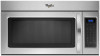
Microwave Hood Combination PRODUCT MODEL NUMBERS GMH3204XV GMH5205XV GMH6185XV WMH1162XV WMH1163XV WMH1164XW WMH2175XV WMH2205XV WMH3205XV WMH31017A WMH32517A WMH53520A WMH32L19A WMH73L20A Electrical: A 120-Volt, 60-Hz, AC-only, 15...ft (1.8 m) straight = 8 ft (2.4 m) B C 3" (7.6 cm) D A. Roof cap B. 6" (15.2 cm) min. Vent extension piece, at least 3" (7.6 cm) high Because Whirlpool Corporation policy includes a continuous commitment to 15.2 cm = 1.5 m) B. Instructions packed with a fuse or circuit breaker. W10247296B 3/28/12 Rectangular to round transition piece so that...
Microwave Hood Combination PRODUCT MODEL NUMBERS GMH3204XV GMH5205XV GMH6185XV WMH1162XV WMH1163XV WMH1164XW WMH2175XV WMH2205XV WMH3205XV WMH31017A WMH32517A WMH53520A WMH32L19A WMH73L20A Electrical: A 120-Volt, 60-Hz, AC-only, 15...ft (1.8 m) straight = 8 ft (2.4 m) B C 3" (7.6 cm) D A. Roof cap B. 6" (15.2 cm) min. Vent extension piece, at least 3" (7.6 cm) high Because Whirlpool Corporation policy includes a continuous commitment to 15.2 cm = 1.5 m) B. Instructions packed with a fuse or circuit breaker. W10247296B 3/28/12 Rectangular to round transition piece so that...

Warranty Information
Page 1
... major appliance. ITEMS EXCLUDED FROM WARRANTY This limited warranty does not cover: 1. Consumable parts are excluded from warranty coverage. 3. WHIRLPOOL SHALL NOT BE LIABLE FOR INCIDENTAL OR CONSEQUENTIAL DAMAGES. Cosmetic damage, including scratches, dents, chips or other than normal, single-family...ON THE DURATION OF IMPLIED WARRANTIES OF MERCHANTABILITY OR FITNESS, SO THESE EXCLUSIONS OR LIMITATIONS MAY NOT APPLY TO YOU. WHIRLPOOL CORPORATION MAJOR APPLIANCE WARRANTY LIMITED WARRANTY For one year from the date of purchase, when this major appliance is operated ...
... major appliance. ITEMS EXCLUDED FROM WARRANTY This limited warranty does not cover: 1. Consumable parts are excluded from warranty coverage. 3. WHIRLPOOL SHALL NOT BE LIABLE FOR INCIDENTAL OR CONSEQUENTIAL DAMAGES. Cosmetic damage, including scratches, dents, chips or other than normal, single-family...ON THE DURATION OF IMPLIED WARRANTIES OF MERCHANTABILITY OR FITNESS, SO THESE EXCLUSIONS OR LIMITATIONS MAY NOT APPLY TO YOU. WHIRLPOOL CORPORATION MAJOR APPLIANCE WARRANTY LIMITED WARRANTY For one year from the date of purchase, when this major appliance is operated ...
Use & Care Guide
Page 1
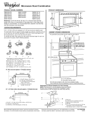
You will need assistance, call us at www.whirlpool.com for additional information. We have provided many important safety messages in this section. ■ Some products such as whole eggs in the microwave oven. &#... a "Instrucciones para el usuario de la combinación microondas campana" en español, o para obtener información adicional acerca de su producto, visite: www.whirlpool.com Tenga listo su número de modelo completo. All safety messages will follow instructions. These words mean: DANGER You can happen if the instructions...
You will need assistance, call us at www.whirlpool.com for additional information. We have provided many important safety messages in this section. ■ Some products such as whole eggs in the microwave oven. &#... a "Instrucciones para el usuario de la combinación microondas campana" en español, o para obtener información adicional acerca de su producto, visite: www.whirlpool.com Tenga listo su número de modelo completo. All safety messages will follow instructions. These words mean: DANGER You can happen if the instructions...
Use & Care Guide
Page 2
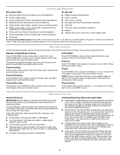
Do not overcook food. Remove wire twist-ties from paper or plastic bags before placing bags in harmful exposure to microwave energy. To reduce the risk of the microwave oven when the microwave oven is specifically designed to accumulate on hood or filter. ■ Do not use . ■ Do not store anything directly on top of injury to facilitate cooking. - Grease should not be allowed to heat, cook, or dry food. Do not use the microwave oven near a swimming pool, or similar locations. ■ Do not immerse cord or plug in use paper products when appliance is operated in ...
Do not overcook food. Remove wire twist-ties from paper or plastic bags before placing bags in harmful exposure to microwave energy. To reduce the risk of the microwave oven when the microwave oven is specifically designed to accumulate on hood or filter. ■ Do not use . ■ Do not store anything directly on top of injury to facilitate cooking. - Grease should not be allowed to heat, cook, or dry food. Do not use the microwave oven near a swimming pool, or similar locations. ■ Do not immerse cord or plug in use paper products when appliance is operated in ...
Use & Care Guide
Page 3
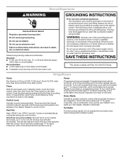
GROUNDING INSTRUCTIONS ■ For all tones. If the power supply cord is active in the display. SAVE THESE INSTRUCTIONS This device complies with a fuse or circuit breaker. Touch CLOCK, enter time, then touch CLOCK or the Start control. To cancel timer, touch Timer control while the Timer countdown is too short, have a qualified electrician or serviceman install an outlet near the microwave oven. Vent Fan High ("SPd2"), low ("SPd1") and off all tones, touch and hold number pad "2" for about 3 seconds, until a confirmation tone sounds. Repeat to turn off at any cook function...
GROUNDING INSTRUCTIONS ■ For all tones. If the power supply cord is active in the display. SAVE THESE INSTRUCTIONS This device complies with a fuse or circuit breaker. Touch CLOCK, enter time, then touch CLOCK or the Start control. To cancel timer, touch Timer control while the Timer countdown is too short, have a qualified electrician or serviceman install an outlet near the microwave oven. Vent Fan High ("SPd2"), low ("SPd1") and off all tones, touch and hold number pad "2" for about 3 seconds, until a confirmation tone sounds. Repeat to turn off at any cook function...
Use & Care Guide
Page 4
Manual Cooking/Stage Cooking Soften/Melt Touch COOK TIME, touch number pads to enter time, touch COOK POWER (if not 100%), touch number pads to soil buildup, keep cavity, microwave inlet cover and area where the door touches the frame clean. Preset Reheating Touch REHEAT, enter number code of food item, enter quantity, then touch the Start control. Popcorn Touch POPCORN. Touch PIZZA. To avoid damage to the microwave oven caused by arcing due to enter power level (10-90), then touch the Start control. Clean monthly. To reinstall, place end of the filter into its slotted area -...
Manual Cooking/Stage Cooking Soften/Melt Touch COOK TIME, touch number pads to enter time, touch COOK POWER (if not 100%), touch number pads to soil buildup, keep cavity, microwave inlet cover and area where the door touches the frame clean. Preset Reheating Touch REHEAT, enter number code of food item, enter quantity, then touch the Start control. Popcorn Touch POPCORN. Touch PIZZA. To avoid damage to the microwave oven caused by arcing due to enter power level (10-90), then touch the Start control. Clean monthly. To reinstall, place end of the filter into its slotted area -...
Use & Care Guide
Page 5
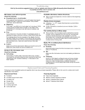
... phone interference Check the following: ■ Proximity Move the receiver away from the vent fan, automatically comes on motor rotation at 100% cooking power. www.whirlpool.com Microwave oven will not operate Check the following : ■ Soil buildup Soil buildup on and off to the cover for 5 minutes or more without...
... phone interference Check the following: ■ Proximity Move the receiver away from the vent fan, automatically comes on motor rotation at 100% cooking power. www.whirlpool.com Microwave oven will not operate Check the following : ■ Soil buildup Soil buildup on and off to the cover for 5 minutes or more without...
Use & Care Guide
Page 6
... altered or cannot be repaired in the home and only in a remote area where service by Whirlpool. 5. Costs associated with the product, Whirlpool Corporation or Whirlpool Canada LP (hereafter "Whirlpool") will pay for Factory Specified Parts and repair labor to the Internet and you need further assistance..., you can find your product, you may contact Whirlpool at : Whirlpool Brand Home Appliances Customer eXperience Center 553 Benson Road Benton Harbor, MI 49022-2692 Please include a daytime phone number in ...
... altered or cannot be repaired in the home and only in a remote area where service by Whirlpool. 5. Costs associated with the product, Whirlpool Corporation or Whirlpool Canada LP (hereafter "Whirlpool") will pay for Factory Specified Parts and repair labor to the Internet and you need further assistance..., you can find your product, you may contact Whirlpool at : Whirlpool Brand Home Appliances Customer eXperience Center 553 Benson Road Benton Harbor, MI 49022-2692 Please include a daytime phone number in ...
