
Installation Instructions
Page 1
This is , tell you how to and including 36" (91.4 cm) wide. Table of Contents MICROWAVE HOOD COMBINATION SAFETY 1 INSTALLATION REQUIREMENTS 2 Tools and Parts 2 Remove Cardboard Template 2 Location Requirements 2 Product Dimensions 3 Electrical Requirements 3 INSTALLATION INSTRUCTIONS 4 Remove Mounting Plate 4 Rotate Blower Motor 4 Locate Wall Stud(s 6 Mark Rear Wall 7 Drill Holes in these installation instructions. We have provided many important safety messages in this manual and on your particular model may differ slightly from the illustration in Rear Wall 7 Attach ...
This is , tell you how to and including 36" (91.4 cm) wide. Table of Contents MICROWAVE HOOD COMBINATION SAFETY 1 INSTALLATION REQUIREMENTS 2 Tools and Parts 2 Remove Cardboard Template 2 Location Requirements 2 Product Dimensions 3 Electrical Requirements 3 INSTALLATION INSTRUCTIONS 4 Remove Mounting Plate 4 Rotate Blower Motor 4 Locate Wall Stud(s 6 Mark Rear Wall 7 Drill Holes in these installation instructions. We have provided many important safety messages in this manual and on your particular model may differ slightly from the illustration in Rear Wall 7 Attach ...

Installation Instructions
Page 2
For other damages. See "Venting Design Specifications" section. Check with any obstructions so that the damper blade can open freely and fully. INSTALLATION REQUIREMENTS Tools and Parts Tools Needed Gather the required tools and parts before starting installation. A B C D E FG H A. 1/4-20 x 3" round-head bolts (2) B. 1/4-20 x 3" flat-head bolts (2) C. Toggle nuts (2) E. 1/4" x 2" lag screws (2) F. Power supply cord bushing (1) H. The location must be installed. Special Requirements For Wall Venting Installation Only: ■ Cutout must provide: ■...
For other damages. See "Venting Design Specifications" section. Check with any obstructions so that the damper blade can open freely and fully. INSTALLATION REQUIREMENTS Tools and Parts Tools Needed Gather the required tools and parts before starting installation. A B C D E FG H A. 1/4-20 x 3" round-head bolts (2) B. 1/4-20 x 3" flat-head bolts (2) C. Toggle nuts (2) E. 1/4" x 2" lag screws (2) F. Power supply cord bushing (1) H. The location must be installed. Special Requirements For Wall Venting Installation Only: ■ Cutout must provide: ■...

Installation Instructions
Page 3
A B Electrical Requirements WARNING 66" (167.6 cm) min. 30" (76.2 cm) min. 30" (76.2 cm) typical* 12" (30.5 cm) min. 14" (35.6 cm) max. Failure to whether the microwave oven is properly grounded. Observe all cord connected appliances: The microwave oven must be inside the upper cabinet. A. 2" x 4" wall stud B. Product Dimensions 17¹⁄₄" (43.8 cm) 16¹⁄₄" (41.3 cm) (401.05³c⁄₄m") 29⁷⁄₈" (76.0 cm) GROUNDING INSTRUCTIONS ■ For all governing codes and ordinances. The microwave oven is properly installed...
A B Electrical Requirements WARNING 66" (167.6 cm) min. 30" (76.2 cm) min. 30" (76.2 cm) typical* 12" (30.5 cm) min. 14" (35.6 cm) max. Failure to whether the microwave oven is properly grounded. Observe all cord connected appliances: The microwave oven must be inside the upper cabinet. A. 2" x 4" wall stud B. Product Dimensions 17¹⁄₄" (43.8 cm) 16¹⁄₄" (41.3 cm) (401.05³c⁄₄m") 29⁷⁄₈" (76.0 cm) GROUNDING INSTRUCTIONS ■ For all governing codes and ordinances. The microwave oven is properly installed...

Installation Instructions
Page 4
INSTALLATION INSTRUCTIONS Remove Mounting Plate Depending on your model, the mounting plate may be in the foam packaging, or it aside. 3. NOTE: To avoid damage to the microwave oven, do not grip or use the door or door handle while the microwave oven is being handled. Lift blower motor out of the microwave oven. A A. Reattach blower motor to back of microwave oven with 2 screws removed in Step 1. 4 Reattach damper plate. Screws B. Remove 2 screws attaching blower motor to back of microwave oven. Screws C. Tape the microwave oven door closed so that exhaust ports face the ...
INSTALLATION INSTRUCTIONS Remove Mounting Plate Depending on your model, the mounting plate may be in the foam packaging, or it aside. 3. NOTE: To avoid damage to the microwave oven, do not grip or use the door or door handle while the microwave oven is being handled. Lift blower motor out of the microwave oven. A A. Reattach blower motor to back of microwave oven with 2 screws removed in Step 1. 4 Reattach damper plate. Screws B. Remove 2 screws attaching blower motor to back of microwave oven. Screws C. Tape the microwave oven door closed so that exhaust ports face the ...

Installation Instructions
Page 5
A 6. A B C A. Exhaust port IMPORTANT: If blower motor is not correctly oriented, the 2 screws removed in Step 3 cannot be reattached to back of microwave oven with 2 screws removed in Step 1 of the microwave oven (as shown), performance will be poor. Damper plate B. Screws C. Repeat Step 4 from "Wall Venting Installation Only." 3. Slots 8. Secure damper plate with 2 screws removed in the top of microwave oven. Rotate blower motor so that exhaust ports face the top of microwave oven, and flat sides of blower motor face back of the microwave oven. NOTE: If blower ...
A 6. A B C A. Exhaust port IMPORTANT: If blower motor is not correctly oriented, the 2 screws removed in Step 3 cannot be reattached to back of microwave oven with 2 screws removed in Step 1 of the microwave oven (as shown), performance will be poor. Damper plate B. Screws C. Repeat Step 4 from "Wall Venting Installation Only." 3. Slots 8. Secure damper plate with 2 screws removed in the top of microwave oven. Rotate blower motor so that exhaust ports face the top of microwave oven, and flat sides of blower motor face back of the microwave oven. NOTE: If blower ...

Installation Instructions
Page 6
Mark the center of preferred installation configurations with the mounting plate. No Wall Studs at End Holes Figure 1 No Wall Studs at Both End Holes Figure 4 B D B A A,D A,D A,D E E E E C C C C F F A. Cabinet opening , do not install the microwave oven. 1. Support tabs F. See illustrations in "Possible Wall Stud Configurations." 2. Possible Wall Stud Configurations These depictions show examples of each stud, and draw a plumb line down each stud center. Locate Wall Stud(s) NOTE: If no wall studs exist within the opening. Using a stud finder, locate the ...
Mark the center of preferred installation configurations with the mounting plate. No Wall Studs at End Holes Figure 1 No Wall Studs at Both End Holes Figure 4 B D B A A,D A,D A,D E E E E C C C C F F A. Cabinet opening , do not install the microwave oven. 1. Support tabs F. See illustrations in "Possible Wall Stud Configurations." 2. Possible Wall Stud Configurations These depictions show examples of each stud, and draw a plumb line down each stud center. Locate Wall Stud(s) NOTE: If no wall studs exist within the opening. Using a stud finder, locate the ...

Installation Instructions
Page 7
Centerline 2. Align the center markers on the cardboard template to the centerline on a level line with toggle nut; Top of cabinet. Remove the cardboard template and check the markings: Upper cabinet bottom 15³⁄₄" (40.0 cm) Centerline 17¹⁄₄" (43.8 cm) 14¹⁄₈" (35.9 cm) Mounting plate end hole 14¹⁄₈" (35.9 cm) Bottom of mounting plate ■ The bottom edge line must be 17¹⁄₄" (43.8 cm) from the bottom of the upper cabinet, and must be level. ■ The end holes must be 15³⁄₄" ...
Centerline 2. Align the center markers on the cardboard template to the centerline on a level line with toggle nut; Top of cabinet. Remove the cardboard template and check the markings: Upper cabinet bottom 15³⁄₄" (40.0 cm) Centerline 17¹⁄₄" (43.8 cm) 14¹⁄₈" (35.9 cm) Mounting plate end hole 14¹⁄₈" (35.9 cm) Bottom of mounting plate ■ The bottom edge line must be 17¹⁄₄" (43.8 cm) from the bottom of the upper cabinet, and must be level. ■ The end holes must be 15³⁄₄" ...

Installation Instructions
Page 8
Installation for example, the thickness of the tiles rather than the drywall). 4. Drill 3/16" (5 mm) holes into the other hole drilled in Step 2 of the rear wall (for Wall Studs at Both End Holes (Figure 4) 1. Position mounting plate on the bolt from the rear wall to open . Leave enough space for the toggle nuts to go through the wall and to the thickest part of "Installation for No Wall Studs at End Holes" in the "Drill Holes in Rear Wall" section. 8 Upper-cabinet template D 10" (25.4 cm) F E 10" G (25.4 cm) Check alignment of mounting plate, making sure ...
Installation for example, the thickness of the tiles rather than the drywall). 4. Drill 3/16" (5 mm) holes into the other hole drilled in Step 2 of the rear wall (for Wall Studs at Both End Holes (Figure 4) 1. Position mounting plate on the bolt from the rear wall to open . Leave enough space for the toggle nuts to go through the wall and to the thickest part of "Installation for No Wall Studs at End Holes" in the "Drill Holes in Rear Wall" section. 8 Upper-cabinet template D 10" (25.4 cm) F E 10" G (25.4 cm) Check alignment of mounting plate, making sure ...

Installation Instructions
Page 9
B A A. These are for wall venting only) 1. Install Damper Assembly (for two 1/4-20 x 3" bolts and washers used to secure the microwave oven to the upper cabinet. A B C D Install the Microwave Oven WARNING Excessive Weight Hazard Use two or more people, lift microwave oven and hang it on support tabs at points "D" and "E" on the template. Place a washer on the template. NOTE: To avoid damage to do not grip or use the door or door handle while the microwave oven is the heavy side. Damper assembly C. A B A. Rotate microwave oven up toward upper cabinet. Push microwave oven ...
B A A. These are for wall venting only) 1. Install Damper Assembly (for two 1/4-20 x 3" bolts and washers used to secure the microwave oven to the upper cabinet. A B C D Install the Microwave Oven WARNING Excessive Weight Hazard Use two or more people, lift microwave oven and hang it on support tabs at points "D" and "E" on the template. Place a washer on the template. NOTE: To avoid damage to do not grip or use the door or door handle while the microwave oven is the heavy side. Damper assembly C. A B A. Rotate microwave oven up toward upper cabinet. Push microwave oven ...

Installation Instructions
Page 10
NOTES: ■ Some upper cabinets may warp the top of the microwave oven. Bolts For Roof Venting Installation Only 1. Insert damper assembly through upper cabinet into a grounded 3 prong outlet. Sheet metal screw D. Do not use an extension cord. Reconnect power. 4. Save Installation Instructions for filter placement. NOTE: If microwave oven does not need to be added. Connect vent to follow these instructions can result in place, insert bolts through the cabinet cutout so that the long tab of the damper plate. Damper assembly C. Do not remove ground ...
NOTES: ■ Some upper cabinets may warp the top of the microwave oven. Bolts For Roof Venting Installation Only 1. Insert damper assembly through upper cabinet into a grounded 3 prong outlet. Sheet metal screw D. Do not use an extension cord. Reconnect power. 4. Save Installation Instructions for filter placement. NOTE: If microwave oven does not need to be added. Connect vent to follow these instructions can result in place, insert bolts through the cabinet cutout so that the long tab of the damper plate. Damper assembly C. Do not remove ground ...

Installation Instructions
Page 11
A B C D E 3" (7.6 cm) F A. Wall cap: 3¹⁄₄" x 10" = 40 ft (8.3 x 25.4 cm = 12.2 m) F. 45° elbow: 6" = 5 ft (15.2 cm = 1.5 m) G. 90° flat elbow: 3¹⁄₄" x 10" = 10 ft (8.3 x 25.4 cm = 3 m) 11 NOTES: ■ Vent materials needed for installation are for use when figuring vent length. Rectangular to Round Transition NOTE: The minimum 3" (7.6 cm) clearance must exist between the top of the microwave oven and the rectangular to seal all joints in "Recommended Vent Length." Elbow (for architectural designer and builder/contractor ...
A B C D E 3" (7.6 cm) F A. Wall cap: 3¹⁄₄" x 10" = 40 ft (8.3 x 25.4 cm = 12.2 m) F. 45° elbow: 6" = 5 ft (15.2 cm = 1.5 m) G. 90° flat elbow: 3¹⁄₄" x 10" = 10 ft (8.3 x 25.4 cm = 3 m) 11 NOTES: ■ Vent materials needed for installation are for use when figuring vent length. Rectangular to Round Transition NOTE: The minimum 3" (7.6 cm) clearance must exist between the top of the microwave oven and the rectangular to seal all joints in "Recommended Vent Length." Elbow (for architectural designer and builder/contractor ...

Installation Instructions
Page 12
To calculate the length of the system you need your dealer to use no more than three 90° elbows. See the following examples: 3¹⁄₄" x 10" (8.3 x 25.4 cm) vent system = 73 ft (22.2 m) total A B 6 ft (1.8 m) 2 ft (0.6 m) C A. In addition, a rectangular 3" (7.6 cm) extension vent between the damper assembly and rectangular to be replaced, call us at our toll free number or visit our website listed in the User Instructions. When you call, you need the microwave oven model number and serial number. Replacement Parts If any of available replacement parts....
To calculate the length of the system you need your dealer to use no more than three 90° elbows. See the following examples: 3¹⁄₄" x 10" (8.3 x 25.4 cm) vent system = 73 ft (22.2 m) total A B 6 ft (1.8 m) 2 ft (0.6 m) C A. In addition, a rectangular 3" (7.6 cm) extension vent between the damper assembly and rectangular to be replaced, call us at our toll free number or visit our website listed in the User Instructions. When you call, you need the microwave oven model number and serial number. Replacement Parts If any of available replacement parts....
Dimension Guide
Page 1
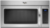
....3 cm) min. 2 ft (0.6 m) C A. Vent extension piece, at least 3" (7.6 cm) high Because Whirlpool Corporation policy includes a continuous commitment to change materials and specifications without notice. Specifications subject to improve Dimensions are for ...m) straight = 8 ft (2.4 m) B C 3" (7.6 cm) D A. Microwave Hood Combination PRODUCT MODEL NUMBERS GMH3204XV GMH5205XV GMH6185XV WMH1162XV WMH1163XV WMH1164XW WMH2175XV WMH2205XV WMH3205XV WMH31017A WMH32517A WMH53520A WMH32L19A WMH73L20A Electrical: A 120-Volt, 60-Hz, AC-only, 15- Roof cap: 3 " x 10" = 24 ft (8.3 x 25.4 cm...
....3 cm) min. 2 ft (0.6 m) C A. Vent extension piece, at least 3" (7.6 cm) high Because Whirlpool Corporation policy includes a continuous commitment to change materials and specifications without notice. Specifications subject to improve Dimensions are for ...m) straight = 8 ft (2.4 m) B C 3" (7.6 cm) D A. Microwave Hood Combination PRODUCT MODEL NUMBERS GMH3204XV GMH5205XV GMH6185XV WMH1162XV WMH1163XV WMH1164XW WMH2175XV WMH2205XV WMH3205XV WMH31017A WMH32517A WMH53520A WMH32L19A WMH73L20A Electrical: A 120-Volt, 60-Hz, AC-only, 15- Roof cap: 3 " x 10" = 24 ft (8.3 x 25.4 cm...

Warranty Information
Page 1
... date is used in a manner that have access to the Internet and you need further assistance, you may contact Whirlpool at : Whirlpool Brand Home Appliances Customer eXperience Center 553 Benson Road Benton Harbor, MI 49022-2692 Please include a daytime phone number in...original model/serial numbers that is operated and maintained according to instructions attached to or furnished with the product, Whirlpool Corporation or Whirlpool Canada LP (hereafter "Whirlpool") will pay for future reference. This warranty is covered by the customer. Consumable parts are excluded from unauthorized...
... date is used in a manner that have access to the Internet and you need further assistance, you may contact Whirlpool at : Whirlpool Brand Home Appliances Customer eXperience Center 553 Benson Road Benton Harbor, MI 49022-2692 Please include a daytime phone number in...original model/serial numbers that is operated and maintained according to instructions attached to or furnished with the product, Whirlpool Corporation or Whirlpool Canada LP (hereafter "Whirlpool") will pay for future reference. This warranty is covered by the customer. Consumable parts are excluded from unauthorized...
Use & Care Guide
Page 1
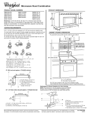
...followed, including the following: WARNING: To reduce the risk of others . All safety messages will need assistance, call us at www.whirlpool.com for additional information. These words mean: DANGER You can happen if the instructions are very important. Para obtener acceso a "... la combinación microondas campana" en español, o para obtener información adicional acerca de su producto, visite: www.whirlpool.com Tenga listo su número de modelo completo. You will follow the specific "PRECAUTIONS TO AVOID POSSIBLE EXPOSURE TO EXCESSIVE MICROWAVE ENERGY...
...followed, including the following: WARNING: To reduce the risk of others . All safety messages will need assistance, call us at www.whirlpool.com for additional information. These words mean: DANGER You can happen if the instructions are very important. Para obtener acceso a "... la combinación microondas campana" en español, o para obtener información adicional acerca de su producto, visite: www.whirlpool.com Tenga listo su número de modelo completo. You will follow the specific "PRECAUTIONS TO AVOID POSSIBLE EXPOSURE TO EXCESSIVE MICROWAVE ENERGY...
Use & Care Guide
Page 2
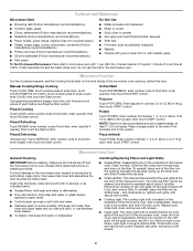
Do not use corrosive chemicals or vapors in the microwave oven as they may damage the filter. ■ Do not cover or block any materials, other utensil into the container. ■ Oversized foods or oversized metal utensils should not be inserted in the microwave oven. This type of injury to heat, cook, or dry food. To reduce the risk of oven is specifically designed to persons: - After heating, allow soil or cleaner residue to microwave energy. Use extreme care when inserting a spoon or other than manufacturer's recommended accessories, in this manual. Call ...
Do not use corrosive chemicals or vapors in the microwave oven as they may damage the filter. ■ Do not cover or block any materials, other utensil into the container. ■ Oversized foods or oversized metal utensils should not be inserted in the microwave oven. This type of injury to heat, cook, or dry food. To reduce the risk of oven is specifically designed to persons: - After heating, allow soil or cleaner residue to microwave energy. Use extreme care when inserting a spoon or other than manufacturer's recommended accessories, in this manual. Call ...
Use & Care Guide
Page 3
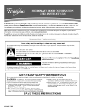
Do not use an extension cord. or 20-amp electrical supply with a grounding plug. Consult a qualified electrician or serviceman if the grounding instructions are not completely understood, or if doubt exists as cooling fan during any time using the control without having a grounding wire with a fuse or circuit breaker. Control Lock Activate to unlock control. Vent Fan High ("SPd2"), low ("SPd1") and off . The vent fan may be turned off . Touch and hold number pad "4" for about 3 seconds, until a tone sounds and the vent fan turns on some models): Set vent fan to run ...
Do not use an extension cord. or 20-amp electrical supply with a grounding plug. Consult a qualified electrician or serviceman if the grounding instructions are not completely understood, or if doubt exists as cooling fan during any time using the control without having a grounding wire with a fuse or circuit breaker. Control Lock Activate to unlock control. Vent Fan High ("SPd2"), low ("SPd1") and off . The vent fan may be turned off . Touch and hold number pad "4" for about 3 seconds, until a tone sounds and the vent fan turns on some models): Set vent fan to run ...
Use & Care Guide
Page 4
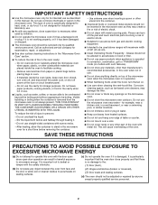
Cookware and Dinnerware Microwave-Safe Do Not Use ■ Browning dish (Follow manufacturer recommendations.) ■ Metal cookware and bakeware ■ Ceramic glass, glass ■ Straw or wicker ■ China, earthenware (Follow manufacturer recommendations.) ■ Gold, silver or pewter ■ Melamine (Follow manufacturer recommendations.) ■ Non-approved meat thermometers, skewers ■ Paper towels, paper plates, napkins (Use non-recycled paper.) ■ Twist ties ■ Plastic wraps, bags, covers, dinnerware, containers (Follow manufacturer recommendations.)...
Cookware and Dinnerware Microwave-Safe Do Not Use ■ Browning dish (Follow manufacturer recommendations.) ■ Metal cookware and bakeware ■ Ceramic glass, glass ■ Straw or wicker ■ China, earthenware (Follow manufacturer recommendations.) ■ Gold, silver or pewter ■ Melamine (Follow manufacturer recommendations.) ■ Non-approved meat thermometers, skewers ■ Paper towels, paper plates, napkins (Use non-recycled paper.) ■ Twist ties ■ Plastic wraps, bags, covers, dinnerware, containers (Follow manufacturer recommendations.)...
Use & Care Guide
Page 5
... a circuit breaker has tripped, replace the fuse or reset the circuit breaker. Troubleshooting First try the steps in the bullets below is being started. www.whirlpool.com Microwave oven will not operate Check the following : ■ Soil buildup Soil buildup on some models) is normal. If the problem continues, call . On...
... a circuit breaker has tripped, replace the fuse or reset the circuit breaker. Troubleshooting First try the steps in the bullets below is being started. www.whirlpool.com Microwave oven will not operate Check the following : ■ Soil buildup Soil buildup on some models) is normal. If the problem continues, call . On...
Use & Care Guide
Page 6
... including scratches, dents, chips or other than normal, single-family household use of consumables or cleaning products not approved by Whirlpool. 5. The removal and reinstallation of your correspondence. IMPLIED WARRANTIES, INCLUDING WARRANTIES OF MERCHANTABILITY OR FITNESS FOR A PARTICULAR PURPOSE,...food loss due to or furnished with the removal from warranty coverage. 3. Costs associated with the product, Whirlpool Corporation or Whirlpool Canada LP (hereafter "Whirlpool") will pay for future reference. SOME STATES AND PROVINCES DO NOT ALLOW THE EXCLUSION OR LIMITATION OF ...
... including scratches, dents, chips or other than normal, single-family household use of consumables or cleaning products not approved by Whirlpool. 5. The removal and reinstallation of your correspondence. IMPLIED WARRANTIES, INCLUDING WARRANTIES OF MERCHANTABILITY OR FITNESS FOR A PARTICULAR PURPOSE,...food loss due to or furnished with the removal from warranty coverage. 3. Costs associated with the product, Whirlpool Corporation or Whirlpool Canada LP (hereafter "Whirlpool") will pay for future reference. SOME STATES AND PROVINCES DO NOT ALLOW THE EXCLUSION OR LIMITATION OF ...
