Dimension Guide
Page 1
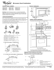
...round transition piece so that a separate circuit serving only this microwave oven be provided. Elbow (for 66" (167.6 cm) installation height. Specifications subject to improve Dimensions are for either type of the vent system including straight .... Vent extension piece, at least 3" (7.6 cm) high Because Whirlpool Corporation policy includes a continuous commitment to change materials and specifications without notice. Ref. A 2 ft (0.6 m) C A. Roof cap B. 6" (15.2 cm) min. See the following examples: A B C PRODUCT DIMENSIONS 17 " (43.8 cm) 16 " (41.3 cm) ...
...round transition piece so that a separate circuit serving only this microwave oven be provided. Elbow (for 66" (167.6 cm) installation height. Specifications subject to improve Dimensions are for either type of the vent system including straight .... Vent extension piece, at least 3" (7.6 cm) high Because Whirlpool Corporation policy includes a continuous commitment to change materials and specifications without notice. Ref. A 2 ft (0.6 m) C A. Roof cap B. 6" (15.2 cm) min. See the following examples: A B C PRODUCT DIMENSIONS 17 " (43.8 cm) 16 " (41.3 cm) ...

Installation Instructions
Page 1
... 2 Product Dimensions 3 Electrical Requirements 3 INSTALLATION INSTRUCTIONS 4 Remove Mounting Plate 4 Rotate Blower Motor 4 Locate Wall Stud(s 6 Mark Rear Wall 7 Drill Holes in Rear Wall 7 Attach Mounting Plate to Wall 8 Prepare Upper Cabinet 8 Install Damper Assembly 9 Install the Microwave Oven 9 ...Complete Installation 10 VENTING DESIGN SPECIFICATIONS 11 ASSISTANCE 12 Replacement Parts 12 Accessories 12 MICROWAVE HOOD COMBINATION SAFETY Your safety and the safety of your particular ...
... 2 Product Dimensions 3 Electrical Requirements 3 INSTALLATION INSTRUCTIONS 4 Remove Mounting Plate 4 Rotate Blower Motor 4 Locate Wall Stud(s 6 Mark Rear Wall 7 Drill Holes in Rear Wall 7 Attach Mounting Plate to Wall 8 Prepare Upper Cabinet 8 Install Damper Assembly 9 Install the Microwave Oven 9 ...Complete Installation 10 VENTING DESIGN SPECIFICATIONS 11 ASSISTANCE 12 Replacement Parts 12 Accessories 12 MICROWAVE HOOD COMBINATION SAFETY Your safety and the safety of your particular ...

Installation Instructions
Page 2
...Round Transition" illustration in "Venting Design Specifications" section. 2 The location must be free of wall structures, be installed. See "Installation Dimensions" illustration. ■ Minimum one 2" x 4" (50.8 x 101.6 mm) wood wall stud and minimum 3/8" (10 mm) thickness ... ■ Scissors ■ 1½" (3.8 cm) diam. Read and follow the instructions provided with your builder or cabinet supplier to withstand the heat produced by the microwave oven for wood studs. A B C D E FG H A. 1/4-20 x 3" round-head bolts (2) B. 1/4-20 x 3" flat-head bolts (2) C. Materials needed &#...
...Round Transition" illustration in "Venting Design Specifications" section. 2 The location must be free of wall structures, be installed. See "Installation Dimensions" illustration. ■ Minimum one 2" x 4" (50.8 x 101.6 mm) wood wall stud and minimum 3/8" (10 mm) thickness ... ■ Scissors ■ 1½" (3.8 cm) diam. Read and follow the instructions provided with your builder or cabinet supplier to withstand the heat produced by the microwave oven for wood studs. A B C D E FG H A. 1/4-20 x 3" round-head bolts (2) B. 1/4-20 x 3" flat-head bolts (2) C. Materials needed &#...

Installation Instructions
Page 3
...cabinet depth Electrical Shock Hazard Plug into an outlet that is too short, have a qualified electrician or serviceman install an outlet near the microwave oven. Do not use of electric shock. A. 2" x 4" wall stud B. In the event of an electrical short circuit, ... to follow these instructions can result in a risk of the grounding plug can result in death, fire, or electrical shock. SAVE THESE INSTRUCTIONS 3 Installation Dimensions NOTE: The grounded 3 prong outlet must be plugged into a grounded 3 prong outlet. A B Electrical Requirements WARNING 66" (167.6 cm) min. 30...
...cabinet depth Electrical Shock Hazard Plug into an outlet that is too short, have a qualified electrician or serviceman install an outlet near the microwave oven. Do not use of electric shock. A. 2" x 4" wall stud B. In the event of an electrical short circuit, ... to follow these instructions can result in a risk of the grounding plug can result in death, fire, or electrical shock. SAVE THESE INSTRUCTIONS 3 Installation Dimensions NOTE: The grounded 3 prong outlet must be plugged into a grounded 3 prong outlet. A B Electrical Requirements WARNING 66" (167.6 cm) min. 30...

Installation Instructions
Page 7
Centerline 2. NOTES: ■ If the front edge of the upper cabinet is damaged or unusable, measure and mark the wall with the dimensions described in Step 4. With the support tabs facing forward (see illustrations in "Locate Wall Stud(s)" section), align the mounting plate center ...at End Holes (Figures 1 & 2) 1. Following are over a wall stud, use 1 lag screw and one corner of the cutout area. 14. Mark Rear Wall The microwave oven must be installed on a level line with each be on a minimum of 1 wall stud, preferably 2, using a minimum of 1 lag screw, preferably 2. 1. Front...
Centerline 2. NOTES: ■ If the front edge of the upper cabinet is damaged or unusable, measure and mark the wall with the dimensions described in Step 4. With the support tabs facing forward (see illustrations in "Locate Wall Stud(s)" section), align the mounting plate center ...at End Holes (Figures 1 & 2) 1. Following are over a wall stud, use 1 lag screw and one corner of the cutout area. 14. Mark Rear Wall The microwave oven must be installed on a level line with each be on a minimum of 1 wall stud, preferably 2, using a minimum of 1 lag screw, preferably 2. 1. Front...

Installation Instructions
Page 8
Drill a 3/16" (5 mm) hole into the wall stud at the end hole marked in the top of the microwave oven. Drill a 3/4" (19 mm) hole through the wall at One End Hole (Figure 3) 1. Wall Stud at the other end hole. Start a toggle nut on at ...(s) in Step 2 of "Installation for No Wall Studs at the other hole drilled in Step 2 of the mounting plate. Make sure the 10" (25.4 cm) dimension from upper cabinet. 3. Spring toggle nut D. Installation for Wall Studs at both end holes. 3. No Wall Studs at End Holes (Figures 1 & 2) NOTE: The mounting plate...
Drill a 3/16" (5 mm) hole into the wall stud at the end hole marked in the top of the microwave oven. Drill a 3/4" (19 mm) hole through the wall at One End Hole (Figure 3) 1. Wall Stud at the other end hole. Start a toggle nut on at ...(s) in Step 2 of "Installation for No Wall Studs at the other hole drilled in Step 2 of the mounting plate. Make sure the 10" (25.4 cm) dimension from upper cabinet. 3. Spring toggle nut D. Installation for Wall Studs at both end holes. 3. No Wall Studs at End Holes (Figures 1 & 2) NOTE: The mounting plate...


