Dimension Guide
Page 1
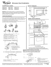
...round vent C. Vent extension piece, at least 3" (7.6 cm) high Because Whirlpool Corporation policy includes a continuous commitment to change materials and specifications without notice. ... Microwave Hood Combination PRODUCT MODEL NUMBERS GMH3204XV GMH5205XV GMH6185XV WMH1162XV WMH1163XV WMH1164XW WMH2175XV WMH2205XV WMH3205XV Electrical: A 120-Volt, 60-Hz, AC-...is typical for wall venting only) E D. A 2 ft (0.6 m) C A. Elbow (for 66" (167.6 cm) installation height. It is recommended. VENTING REQUIREMENTS A 3¹⁄₄" x 10" (8.3 x 25.4 cm) rectangular or 6" (...
...round vent C. Vent extension piece, at least 3" (7.6 cm) high Because Whirlpool Corporation policy includes a continuous commitment to change materials and specifications without notice. ... Microwave Hood Combination PRODUCT MODEL NUMBERS GMH3204XV GMH5205XV GMH6185XV WMH1162XV WMH1163XV WMH1164XW WMH2175XV WMH2205XV WMH3205XV Electrical: A 120-Volt, 60-Hz, AC-...is typical for wall venting only) E D. A 2 ft (0.6 m) C A. Elbow (for 66" (167.6 cm) installation height. It is recommended. VENTING REQUIREMENTS A 3¹⁄₄" x 10" (8.3 x 25.4 cm) rectangular or 6" (...

Installation Instructions
Page 1
...killed or seriously injured if you how to Wall 8 Prepare Upper Cabinet 8 Install Damper Assembly 9 Install the Microwave Oven 9 Complete Installation 10 VENTING DESIGN SPECIFICATIONS 11 ASSISTANCE 12 Replacement Parts 12 Accessories 12 MICROWAVE HOOD... instructions are very important. Table of Contents MICROWAVE HOOD COMBINATION SAFETY 1 INSTALLATION REQUIREMENTS 2 Tools and Parts 2 Remove Cardboard Template 2 Location Requirements 2 Product Dimensions 3 Electrical Requirements 3 INSTALLATION INSTRUCTIONS 4 Remove Mounting Plate 4 Rotate Blower Motor 4 Locate Wall Stud...
...killed or seriously injured if you how to Wall 8 Prepare Upper Cabinet 8 Install Damper Assembly 9 Install the Microwave Oven 9 Complete Installation 10 VENTING DESIGN SPECIFICATIONS 11 ASSISTANCE 12 Replacement Parts 12 Accessories 12 MICROWAVE HOOD... instructions are very important. Table of Contents MICROWAVE HOOD COMBINATION SAFETY 1 INSTALLATION REQUIREMENTS 2 Tools and Parts 2 Remove Cardboard Template 2 Location Requirements 2 Product Dimensions 3 Electrical Requirements 3 INSTALLATION INSTRUCTIONS 4 Remove Mounting Plate 4 Rotate Blower Motor 4 Locate Wall Stud...

Installation Instructions
Page 2
...opening . ■ Support for 1/4" x 2" lag screws ■ Scissors ■ 1½" (3.8 cm) diam. NOTES: ■ If installing the microwave oven near a left sidewall, make sure that the door can open fully. ■ Some cabinet and building materials are for wall...Design Specifications" section. The piece inside upper cabinet. Cut along the perforation to Round Transition" illustration in "Venting Design Specifications" section. 2 See "Installation Dimensions" illustration. ■ Minimum one 2" x 4" (50.8 x 101.6 mm) wood wall stud and minimum 3/8" (10 mm) thickness ...
...opening . ■ Support for 1/4" x 2" lag screws ■ Scissors ■ 1½" (3.8 cm) diam. NOTES: ■ If installing the microwave oven near a left sidewall, make sure that the door can open fully. ■ Some cabinet and building materials are for wall...Design Specifications" section. The piece inside upper cabinet. Cut along the perforation to Round Transition" illustration in "Venting Design Specifications" section. 2 See "Installation Dimensions" illustration. ■ Minimum one 2" x 4" (50.8 x 101.6 mm) wood wall stud and minimum 3/8" (10 mm) thickness ...

Installation Instructions
Page 3
... Volt, 60 Hz, AC only, 15- Failure to whether the microwave oven is too short, have a qualified electrician or serviceman install an outlet near the microwave oven. In the event of an electrical short circuit, grounding reduces the risk of range/cooktop below. ...microwave oven. See "Electrical Requirements" section. Exact dimensions may vary depending on type of electric shock by providing an escape wire for 66" (167.6 cm) installation height. SAVE THESE INSTRUCTIONS 3 A B Electrical Requirements WARNING 66" (167.6 cm) min. 30" (76.2 cm) min. 30" (76.2 cm) typical...
... Volt, 60 Hz, AC only, 15- Failure to whether the microwave oven is too short, have a qualified electrician or serviceman install an outlet near the microwave oven. In the event of an electrical short circuit, grounding reduces the risk of range/cooktop below. ...microwave oven. See "Electrical Requirements" section. Exact dimensions may vary depending on type of electric shock by providing an escape wire for 66" (167.6 cm) installation height. SAVE THESE INSTRUCTIONS 3 A B Electrical Requirements WARNING 66" (167.6 cm) min. 30" (76.2 cm) min. 30" (76.2 cm) typical...

Installation Instructions
Page 4
...top of the microwave oven. Screws (in Step 3. 7. Damper plate tabs D. Make sure damper plate tabs are using recirculation installation. Blower motor 5. Slide damper plate toward the front of microwave oven. Reattach damper plate. Keep damper plate and screws together and set... for recirculation installation. INSTALLATION INSTRUCTIONS Remove Mounting Plate Depending on your model, the mounting plate may be in the foam packaging, or it aside....
...top of the microwave oven. Screws (in Step 3. 7. Damper plate tabs D. Make sure damper plate tabs are using recirculation installation. Blower motor 5. Slide damper plate toward the front of microwave oven. Reattach damper plate. Keep damper plate and screws together and set... for recirculation installation. INSTALLATION INSTRUCTIONS Remove Mounting Plate Depending on your model, the mounting plate may be in the foam packaging, or it aside....

Installation Instructions
Page 5
... shown), performance will be reattached to back of microwave oven with 2 screws removed in the top of "Wall Venting Installation Only." Damper plate B. Slots 8. Roof Venting Installation Only 1. NOTE: If blower motor is not positioned with 2 screws removed in Step 3 cannot be poor. Rotate blower... motor so that exhaust ports face the top of microwave oven, and flat sides of blower motor face back of "Wall Venting Installation Only." 5 Securely tighten screws. Exhaust port IMPORTANT: If blower motor is not correctly oriented, the 2 screws removed in Step 1 of...
... shown), performance will be reattached to back of microwave oven with 2 screws removed in the top of "Wall Venting Installation Only." Damper plate B. Slots 8. Roof Venting Installation Only 1. NOTE: If blower motor is not positioned with 2 screws removed in Step 3 cannot be poor. Rotate blower... motor so that exhaust ports face the top of microwave oven, and flat sides of blower motor face back of "Wall Venting Installation Only." 5 Securely tighten screws. Exhaust port IMPORTANT: If blower motor is not correctly oriented, the 2 screws removed in Step 1 of...

Installation Instructions
Page 6
.... See illustrations in "Possible Wall Stud Configurations." 2. Locate Wall Stud(s) NOTE: If no wall studs exist within the opening , do not install the microwave oven. 1. Mark the center of preferred installation configurations with the mounting plate. Wall Stud at One End Hole Figure 3 Wall Studs at End Holes Figure 2 B C C C D B D A A A A E E E E F F NOTE: If wall...
.... See illustrations in "Possible Wall Stud Configurations." 2. Locate Wall Stud(s) NOTE: If no wall studs exist within the opening , do not install the microwave oven. 1. Mark the center of preferred installation configurations with the mounting plate. Wall Stud at One End Hole Figure 3 Wall Studs at End Holes Figure 2 B C C C D B D A A A A E E E E F F NOTE: If wall...

Installation Instructions
Page 7
... at End Holes (Figures 1 & 2) 1. Cardboard template C. Holding the cardboard template in place, mark both end holes. They must each other. Wall Venting Installation Only Upper cabinet bottom ³⁄₈" (1 cm) 4" (10.2 cm) Centerline 6" (15.2 cm) 6" (15.2 cm) 8. Using measuring tape,... measure out 6" (15.2 cm) on both end holes are 3 installation configurations. if 1 end hole is butted up against the bottom edge of the opening. A A. Rear wall B. Front edge of cabinet. Holding the mounting ...
... at End Holes (Figures 1 & 2) 1. Cardboard template C. Holding the cardboard template in place, mark both end holes. They must each other. Wall Venting Installation Only Upper cabinet bottom ³⁄₈" (1 cm) 4" (10.2 cm) Centerline 6" (15.2 cm) 6" (15.2 cm) 8. Using measuring tape,... measure out 6" (15.2 cm) on both end holes are 3 installation configurations. if 1 end hole is butted up against the bottom edge of the opening. A A. Rear wall B. Front edge of cabinet. Holding the mounting ...

Installation Instructions
Page 8
... round-head bolt B. Drywall 5. No Wall Studs at End Holes (Figures 1 & 2) NOTE: The mounting plate must be secured to the thickest part of "Installation for Wall Stud at One End Hole (Figure 3) 1. Check alignment of the mounting plate. Check alignment of "Mark Rear Wall." Make sure the 10" (25...on the wall. 4. Mounting plate C. Securely tighten the lag screws. Drill a 3/16" (5 mm) hole into the remaining end hole. 6. Installation for the toggle nuts to go through the wall at One End Hole (Figure 3) 1. Position mounting plate on the rear wall. Securely tighten all...
... round-head bolt B. Drywall 5. No Wall Studs at End Holes (Figures 1 & 2) NOTE: The mounting plate must be secured to the thickest part of "Installation for Wall Stud at One End Hole (Figure 3) 1. Check alignment of the mounting plate. Check alignment of "Mark Rear Wall." Make sure the 10" (25...on the wall. 4. Mounting plate C. Securely tighten the lag screws. Drill a 3/16" (5 mm) hole into the remaining end hole. 6. Installation for the toggle nuts to go through the wall at One End Hole (Figure 3) 1. Position mounting plate on the rear wall. Securely tighten all...

Installation Instructions
Page 9
...bolt and place inside upper cabinet near the 3/8" (10 mm) holes. 2. These are for wall venting only) 1. For Roof Venting Installation Only 7. Position the damper assembly on Upper Cabinet Template. 8. NOTE: If venting through the power supply cord hole in back or other ...Sheet metal screws 3. A B A. Power supply cord bushing 6. Handle the microwave oven gently. 1. Using 2 or more people to move and install microwave oven. Damper assembly C. Secure damper assembly with 2 sheet metal screws. Rotate microwave oven up toward upper cabinet. Back of microwave oven still ...
...bolt and place inside upper cabinet near the 3/8" (10 mm) holes. 2. These are for wall venting only) 1. For Roof Venting Installation Only 7. Position the damper assembly on Upper Cabinet Template. 8. NOTE: If venting through the power supply cord hole in back or other ...Sheet metal screws 3. A B A. Power supply cord bushing 6. Handle the microwave oven gently. 1. Using 2 or more people to move and install microwave oven. Damper assembly C. Secure damper assembly with 2 sheet metal screws. Rotate microwave oven up toward upper cabinet. Back of microwave oven still ...

Installation Instructions
Page 10
...has not blown, or that the power supply cord is not positioned as the space between upper cabinet and microwave oven. Save Installation Instructions for troubleshooting information. Longer or shorter bolts are available at least one person holding it in death, fire, or electrical shock... adjusted, skip steps 7-9. 7. Connect vent to provide) may require bolts longer or shorter than 3" (7.6 cm). Do not use . 10 Installation is required, rotate microwave oven downward. NOTE: If microwave oven does not need to be added. Loosen mounting plate screws. Adjust mounting plate ...
...has not blown, or that the power supply cord is not positioned as the space between upper cabinet and microwave oven. Save Installation Instructions for troubleshooting information. Longer or shorter bolts are available at least one person holding it in death, fire, or electrical shock... adjusted, skip steps 7-9. 7. Connect vent to provide) may require bolts longer or shorter than 3" (7.6 cm). Do not use . 10 Installation is required, rotate microwave oven downward. NOTE: If microwave oven does not need to be added. Loosen mounting plate screws. Adjust mounting plate ...

Installation Instructions
Page 11
...Rectangular to round transition piece: 3¹⁄₄" x 10" to 6" = 5 ft (8.3 x 25.4 cm to round transition piece F. For optimal venting installation, we recommend: ■ using roof or wall caps that have back draft dampers ■ using a rigid metal vent ■ using the most direct route...Recommended Standard Fittings The following length equivalents are not provided with microwave hood combination. ■ We do not recommend using recirculation installation. Do not vent exhaust air into concealed spaces, such as spaces within the wall for use when figuring vent length. If...
...Rectangular to round transition piece: 3¹⁄₄" x 10" to 6" = 5 ft (8.3 x 25.4 cm to round transition piece F. For optimal venting installation, we recommend: ■ using roof or wall caps that have back draft dampers ■ using a rigid metal vent ■ using the most direct route...Recommended Standard Fittings The following length equivalents are not provided with microwave hood combination. ■ We do not recommend using recirculation installation. Do not vent exhaust air into concealed spaces, such as spaces within the wall for use when figuring vent length. If...

Installation Instructions
Page 12
...elbows. In addition, a rectangular 3" (7.6 cm) extension vent between the damper assembly and rectangular to round transition piece must be installed to keep the damper from your authorized dealer or service center for either type of the microwave oven. If you need additional ... 10" (8.3 x 25.4 cm) rectangular or 6" (15.2 cm) round vent should be used in the system. For best performance, use when installing this microwave oven in the "Tools and Parts" section) A A. Both numbers can be used. Filler panels Filler Panel Kit Number 8171336 8171337 8171338 ...
...elbows. In addition, a rectangular 3" (7.6 cm) extension vent between the damper assembly and rectangular to round transition piece must be installed to keep the damper from your authorized dealer or service center for either type of the microwave oven. If you need additional ... 10" (8.3 x 25.4 cm) rectangular or 6" (15.2 cm) round vent should be used in the system. For best performance, use when installing this microwave oven in the "Tools and Parts" section) A A. Both numbers can be used. Filler panels Filler Panel Kit Number 8171336 8171337 8171338 ...
Owners Manual
Page 1
...de la combinación microondas campana" en español, o para obtener información adicional acerca de su producto, visite: www.whirlpool.com Tenga listo su número de modelo completo. Puede encontrar su número de modelo y de serie en la etiqueta ubicada ... you still need your model and serial number located on your appliance. If you should experience a problem not covered in the provided Installation Instructions. You will follow instructions. IMPORTANT SAFETY INSTRUCTIONS When using the microwave oven. ■ Read and follow instructions. for purchasing this...
...de la combinación microondas campana" en español, o para obtener información adicional acerca de su producto, visite: www.whirlpool.com Tenga listo su número de modelo completo. Puede encontrar su número de modelo y de serie en la etiqueta ubicada ... you still need your model and serial number located on your appliance. If you should experience a problem not covered in the provided Installation Instructions. You will follow instructions. IMPORTANT SAFETY INSTRUCTIONS When using the microwave oven. ■ Read and follow instructions. for purchasing this...
Owners Manual
Page 3
...; A time-delay fuse or time-delay circuit breaker. ■ A separate circuit serving only this microwave oven. If the power supply cord is properly installed and grounded. Touch CLOCK, enter time, then touch CLOCK or the Start control. Touch and hold the Cancel control for about 3 seconds until 2 tones.... or P.M. This is a 12-hour (12:00-11:59) clock, with plates that is too short, have a qualified electrician or serviceman install an outlet near the microwave oven. Comes on . Tones Programming tones and signals. Touch the Options or Setup control to the microwave oven, always ...
...; A time-delay fuse or time-delay circuit breaker. ■ A separate circuit serving only this microwave oven. If the power supply cord is properly installed and grounded. Touch CLOCK, enter time, then touch CLOCK or the Start control. Touch and hold the Cancel control for about 3 seconds until 2 tones.... or P.M. This is a 12-hour (12:00-11:59) clock, with plates that is too short, have a qualified electrician or serviceman install an outlet near the microwave oven. Comes on . Tones Programming tones and signals. Touch the Options or Setup control to the microwave oven, always ...
Owners Manual
Page 6
... reference. Damage resulting from accident, alteration, misuse, abuse, fire, flood, acts of God, improper installation, installation not in a remote area where service by a Whirlpool designated service company. Repairs to parts or systems resulting from warranty coverage. 3. Expenses for travel and ...appliance, unless such damage results from defects in which it is installed in an inaccessible location or is not installed in accordance with the product, Whirlpool Corporation or Whirlpool Canada LP (hereafter "Whirlpool") will pay for repairs. LIMITATION OF REMEDIES CUSTOMER'S SOLE ...
... reference. Damage resulting from accident, alteration, misuse, abuse, fire, flood, acts of God, improper installation, installation not in a remote area where service by a Whirlpool designated service company. Repairs to parts or systems resulting from warranty coverage. 3. Expenses for travel and ...appliance, unless such damage results from defects in which it is installed in an inaccessible location or is not installed in accordance with the product, Whirlpool Corporation or Whirlpool Canada LP (hereafter "Whirlpool") will pay for repairs. LIMITATION OF REMEDIES CUSTOMER'S SOLE ...

Warranty
Page 1
... only when the major appliance is used in a manner that have access to correct the installation of consumables or cleaning products not approved by Whirlpool. 5. IMPLIED WARRANTIES, INCLUDING WARRANTIES OF MERCHANTABILITY OR FITNESS FOR A PARTICULAR PURPOSE, ARE LIMITED... freezer product failures. 7. Consumable parts are excluded from defects in a remote area where service by a Whirlpool designated service company. Costs associated with published installation instructions. 11. Repairs to parts or systems resulting from accident, alteration, misuse, abuse, fire, flood,...
... only when the major appliance is used in a manner that have access to correct the installation of consumables or cleaning products not approved by Whirlpool. 5. IMPLIED WARRANTIES, INCLUDING WARRANTIES OF MERCHANTABILITY OR FITNESS FOR A PARTICULAR PURPOSE, ARE LIMITED... freezer product failures. 7. Consumable parts are excluded from defects in a remote area where service by a Whirlpool designated service company. Costs associated with published installation instructions. 11. Repairs to parts or systems resulting from accident, alteration, misuse, abuse, fire, flood,...


