Dimension Guide
Page 1
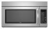
... m) C A. Vent extension piece, at least 3" (7.6 cm) high Because Whirlpool Corporation policy includes a continuous commitment to round transition piece so that a separate ... 40 ft (12.2 m) C. 2 ft (0.6 m) + 6 ft (1.8 m) straight = 8 ft (2.4 m) B C 3" (7.6 cm) D A. Exact dimensions may vary depending on type of the system you need, add the equivalent length for wall venting only) E D. Wall cap F E. 3 " x 10" ... Microwave Hood Combination PRODUCT MODEL NUMBERS GMH3204XV GMH5205XV GMH6185XV WMH1162XV WMH1163XV WMH1164XW WMH2175XV WMH2205XV WMH3205XV Electrical: A 120-Volt, 60-...
... m) C A. Vent extension piece, at least 3" (7.6 cm) high Because Whirlpool Corporation policy includes a continuous commitment to round transition piece so that a separate ... 40 ft (12.2 m) C. 2 ft (0.6 m) + 6 ft (1.8 m) straight = 8 ft (2.4 m) B C 3" (7.6 cm) D A. Exact dimensions may vary depending on type of the system you need, add the equivalent length for wall venting only) E D. Wall cap F E. 3 " x 10" ... Microwave Hood Combination PRODUCT MODEL NUMBERS GMH3204XV GMH5205XV GMH6185XV WMH1162XV WMH1163XV WMH1164XW WMH2175XV WMH2205XV WMH3205XV Electrical: A 120-Volt, 60-...

Installation Instructions
Page 1
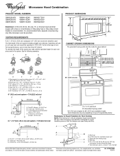
... important safety messages in these installation instructions. Table of Contents MICROWAVE HOOD COMBINATION SAFETY 1 INSTALLATION REQUIREMENTS 2 Tools and Parts 2 Remove Cardboard Template 2 Location Requirements 2 Product Dimensions 3 Electrical Requirements 3 INSTALLATION INSTRUCTIONS 4 Remove Mounting Plate 4 Rotate Blower Motor 4 Locate Wall Stud(s 6 Mark Rear Wall 7 Drill Holes in Rear Wall 7 Attach Mounting Plate to...
... important safety messages in these installation instructions. Table of Contents MICROWAVE HOOD COMBINATION SAFETY 1 INSTALLATION REQUIREMENTS 2 Tools and Parts 2 Remove Cardboard Template 2 Location Requirements 2 Product Dimensions 3 Electrical Requirements 3 INSTALLATION INSTRUCTIONS 4 Remove Mounting Plate 4 Rotate Blower Motor 4 Locate Wall Stud(s 6 Mark Rear Wall 7 Drill Holes in Rear Wall 7 Attach Mounting Plate to...

Installation Instructions
Page 2
... piece from the rest of clearance between the wall and the microwave oven, so that the damper blade can open freely and fully. See "Installation Dimensions" illustration. ■ Minimum one 2" x 4" (50.8 x 101.6 mm) wood wall stud and minimum 3/8" (10 mm) thickness drywall or plaster/lath within cabinet opening where the microwave... be sure to Round Transition" illustration in "Venting Design Specifications" section. 2 Special Requirements For Wall Venting Installation Only: ■ Cutout must provide: ■ Minimum installation dimensions.
... piece from the rest of clearance between the wall and the microwave oven, so that the damper blade can open freely and fully. See "Installation Dimensions" illustration. ■ Minimum one 2" x 4" (50.8 x 101.6 mm) wood wall stud and minimum 3/8" (10 mm) thickness drywall or plaster/lath within cabinet opening where the microwave... be sure to Round Transition" illustration in "Venting Design Specifications" section. 2 Special Requirements For Wall Venting Installation Only: ■ Cutout must provide: ■ Minimum installation dimensions.

Installation Instructions
Page 3
.... The plug must be plugged into a grounded 3 prong outlet. Grounded 3 prong outlet *30" (76.2 cm) is properly installed and grounded. Product Dimensions 17¹⁄₄" (43.8 cm) 16¹⁄₄" (41.3 cm) (401.05³c⁄₄m") 29⁷⁄₈" (76.0... cm) GROUNDING INSTRUCTIONS ■ For all governing codes and ordinances. Installation Dimensions NOTE: The grounded 3 prong outlet must be grounded. Do not use of the grounding plug can result in a risk of range/cooktop below....
.... The plug must be plugged into a grounded 3 prong outlet. Grounded 3 prong outlet *30" (76.2 cm) is properly installed and grounded. Product Dimensions 17¹⁄₄" (43.8 cm) 16¹⁄₄" (41.3 cm) (401.05³c⁄₄m") 29⁷⁄₈" (76.0... cm) GROUNDING INSTRUCTIONS ■ For all governing codes and ordinances. Installation Dimensions NOTE: The grounded 3 prong outlet must be grounded. Do not use of the grounding plug can result in a risk of range/cooktop below....

Installation Instructions
Page 7
...;₄" (43.8 cm) from the bottom of the cabinet. ■ If the cardboard template is damaged or unusable, measure and mark the wall with the dimensions described in Step 4. Drill Holes in Rear Wall In addition to being installed on both end holes marked in Step 3 of cabinet. Following are ideal...
...;₄" (43.8 cm) from the bottom of the cabinet. ■ If the cardboard template is damaged or unusable, measure and mark the wall with the dimensions described in Step 4. Drill Holes in Rear Wall In addition to being installed on both end holes marked in Step 3 of cabinet. Following are ideal...

Installation Instructions
Page 8
... Step 2 of the microwave oven. Refer to Figure 3 in "Possible Wall Stud Configurations" in Step 2 of the mounting plate. Make sure the 10" (25.4 cm) dimension from the back of "Installation for No Wall Studs at the other hole drilled in "Locate Wall Stud(s)" section. Insert lag screw(s) into the hole...
... Step 2 of the microwave oven. Refer to Figure 3 in "Possible Wall Stud Configurations" in Step 2 of the mounting plate. Make sure the 10" (25.4 cm) dimension from the back of "Installation for No Wall Studs at the other hole drilled in "Locate Wall Stud(s)" section. Insert lag screw(s) into the hole...


