Dimension Guide
Page 1
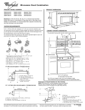
...90° elbows = 20 ft (6.1 m) B. 1 wall cap = 40 ft (12.2 m) C. 1 rectangular to improve Dimensions are for Roof Venting NOTE: The minimum 3" (7.6 cm) clearance must be provided. ® Microwave Hood Combination PRODUCT MODEL NUMBERS ...-only, 15- A time-delay fuse or time-delay circuit breaker is typical for each vent piece used . Vent extension piece, at least 3" (7.6 cm) high Because Whirlpool Corporation policy includes a continuous commitment to round transition piece = 5 ft (1.5 m) D. 2 ft (0.6 m) + 6 ft (1.8 m) straight = 8 ft (2.4 m) D 3 " x 10" (8.3 x 25.4 cm) vent...
...90° elbows = 20 ft (6.1 m) B. 1 wall cap = 40 ft (12.2 m) C. 1 rectangular to improve Dimensions are for Roof Venting NOTE: The minimum 3" (7.6 cm) clearance must be provided. ® Microwave Hood Combination PRODUCT MODEL NUMBERS ...-only, 15- A time-delay fuse or time-delay circuit breaker is typical for each vent piece used . Vent extension piece, at least 3" (7.6 cm) high Because Whirlpool Corporation policy includes a continuous commitment to round transition piece = 5 ft (1.5 m) D. 2 ft (0.6 m) + 6 ft (1.8 m) straight = 8 ft (2.4 m) D 3 " x 10" (8.3 x 25.4 cm) vent...

Installation Instructions
Page 1
Table of Contents MICROWAVE HOOD COMBINATION SAFETY 1 INSTALLATION REQUIREMENTS 2 Tools and Parts 2 Remove Cardboard Template 2 Location Requirements 2 Product Dimensions 3 Electrical Requirements 3 INSTALLATION INSTRUCTIONS 4 Remove Mounting Plate 4 Rotate Blower Motor 4 Locate Wall Stud(s 6 Mark Rear Wall 7 Drill Holes in Rear Wall 7 Attach Mounting Plate to ...
Table of Contents MICROWAVE HOOD COMBINATION SAFETY 1 INSTALLATION REQUIREMENTS 2 Tools and Parts 2 Remove Cardboard Template 2 Location Requirements 2 Product Dimensions 3 Electrical Requirements 3 INSTALLATION INSTRUCTIONS 4 Remove Mounting Plate 4 Rotate Blower Motor 4 Locate Wall Stud(s 6 Mark Rear Wall 7 Drill Holes in Rear Wall 7 Attach Mounting Plate to ...

Installation Instructions
Page 2
..., make sure that the damper blade can open freely and fully. Special Requirements For Wall Venting Installation Only: ■ Cutout must provide: ■ Minimum installation dimensions. A B C D E FG H A. 1/4-20 x 3" round-head bolts (2) B. 1/4-20 x 3" flat-head bolts (2) C. Sheet metal screws (2) G. ... ■ Pencil ■ 7/16" socket wrench ■ Masking tape or thumbtacks (or box wrench) for use appropriate fasteners. See "Installation Dimensions" illustration. ■ Minimum one 2" x 4" (50.8 x 101.6 mm) wood wall stud and minimum 3/8" (10 mm) thickness drywall or...
..., make sure that the damper blade can open freely and fully. Special Requirements For Wall Venting Installation Only: ■ Cutout must provide: ■ Minimum installation dimensions. A B C D E FG H A. 1/4-20 x 3" round-head bolts (2) B. 1/4-20 x 3" flat-head bolts (2) C. Sheet metal screws (2) G. ... ■ Pencil ■ 7/16" socket wrench ■ Masking tape or thumbtacks (or box wrench) for use appropriate fasteners. See "Installation Dimensions" illustration. ■ Minimum one 2" x 4" (50.8 x 101.6 mm) wood wall stud and minimum 3/8" (10 mm) thickness drywall or...

Installation Instructions
Page 3
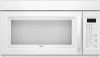
...cabinet. See "Electrical Requirements" section. Do not use an extension cord. Required: ■ A 120 Volt, 60 Hz, AC only, 15- Product Dimensions 17¹⁄₄" (43.8 cm) 16¹⁄₄" (41.3 cm) (401.05³c⁄₄m") 29⁷⁄₈" (76.... SAVE THESE INSTRUCTIONS 3 Grounded 3 prong outlet *30" (76.2 cm) is properly installed and grounded. Do not use an adapter. Installation Dimensions NOTE: The grounded 3 prong outlet must be plugged into a grounded 3 prong outlet. upper cabinet and side cabinet depth Electrical Shock Hazard Plug ...
...cabinet. See "Electrical Requirements" section. Do not use an extension cord. Required: ■ A 120 Volt, 60 Hz, AC only, 15- Product Dimensions 17¹⁄₄" (43.8 cm) 16¹⁄₄" (41.3 cm) (401.05³c⁄₄m") 29⁷⁄₈" (76.... SAVE THESE INSTRUCTIONS 3 Grounded 3 prong outlet *30" (76.2 cm) is properly installed and grounded. Do not use an adapter. Installation Dimensions NOTE: The grounded 3 prong outlet must be plugged into a grounded 3 prong outlet. upper cabinet and side cabinet depth Electrical Shock Hazard Plug ...

Installation Instructions
Page 7
... over a wall stud, use 2 lag screws. Refer to the wall stud centerline(s). Mark Rear Wall The microwave oven must be on a level line with the dimensions described in Step 4. With the support tabs facing forward (see illustrations in "Locate Wall Stud(s)" section), align the mounting plate center markers to the horizontal...
... over a wall stud, use 2 lag screws. Refer to the wall stud centerline(s). Mark Rear Wall The microwave oven must be on a level line with the dimensions described in Step 4. With the support tabs facing forward (see illustrations in "Locate Wall Stud(s)" section), align the mounting plate center markers to the horizontal...

Installation Instructions
Page 8
... has a frame around it fits inside the frame, against drywall. Installation for Wall Stud at One End Hole (Figure 3) 1. Make sure the 10" (25.4 cm) dimension from the back of "Mark Rear Wall." 2. Insert lag screw(s) into the hole(s) drilled into the wall stud at the end hole marked in the...
... has a frame around it fits inside the frame, against drywall. Installation for Wall Stud at One End Hole (Figure 3) 1. Make sure the 10" (25.4 cm) dimension from the back of "Mark Rear Wall." 2. Insert lag screw(s) into the hole(s) drilled into the wall stud at the end hole marked in the...


