Dimension Guide
Page 1
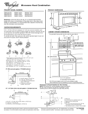
...Two 90° elbows = 20 ft (6.1 m) B. 1 wall cap = 40 ft (12.2 m) C. 1 rectangular to improve Dimensions are for each vent piece used . Exact dimensions may vary depending on type of vent. Rectangular to change materials and specifications without notice. Roof cap B. 6" (15.2 cm) min.... Elbow (for either type of range/cooktop below. Vent extension piece, at least 3" (7.6 cm) high Because Whirlpool Corporation policy ...
...Two 90° elbows = 20 ft (6.1 m) B. 1 wall cap = 40 ft (12.2 m) C. 1 rectangular to improve Dimensions are for each vent piece used . Exact dimensions may vary depending on type of vent. Rectangular to change materials and specifications without notice. Roof cap B. 6" (15.2 cm) min.... Elbow (for either type of range/cooktop below. Vent extension piece, at least 3" (7.6 cm) high Because Whirlpool Corporation policy ...

Installation Instructions
Page 1
Table of Contents MICROWAVE HOOD COMBINATION SAFETY 1 INSTALLATION REQUIREMENTS 2 Tools and Parts 2 Remove Cardboard Template 2 Location Requirements 2 Product Dimensions 3 Electrical Requirements 3 INSTALLATION INSTRUCTIONS 4 Remove Mounting Plate 4 Rotate Blower Motor 4 Locate Wall Stud(s 6 Mark Rear Wall 7 Drill Holes in these installation instructions. W10247296B The appearance ...
Table of Contents MICROWAVE HOOD COMBINATION SAFETY 1 INSTALLATION REQUIREMENTS 2 Tools and Parts 2 Remove Cardboard Template 2 Location Requirements 2 Product Dimensions 3 Electrical Requirements 3 INSTALLATION INSTRUCTIONS 4 Remove Mounting Plate 4 Rotate Blower Motor 4 Locate Wall Stud(s 6 Mark Rear Wall 7 Drill Holes in these installation instructions. W10247296B The appearance ...

Installation Instructions
Page 2
...parts before starting installation. A B C D E FG H A. 1/4-20 x 3" round-head bolts (2) B. 1/4-20 x 3" flat-head bolts (2) C. See "Installation Dimensions" illustration. ■ Minimum one 2" x 4" (50.8 x 101.6 mm) wood wall stud and minimum 3/8" (10 mm) thickness drywall or plaster/lath within cabinet ...the cardboard packaging. 2. Special Requirements For Wall Venting Installation Only: ■ Cutout must provide: ■ Minimum installation dimensions. Read and follow the instructions provided with your builder or cabinet supplier to it during the "Mark Rear Wall" part...
...parts before starting installation. A B C D E FG H A. 1/4-20 x 3" round-head bolts (2) B. 1/4-20 x 3" flat-head bolts (2) C. See "Installation Dimensions" illustration. ■ Minimum one 2" x 4" (50.8 x 101.6 mm) wood wall stud and minimum 3/8" (10 mm) thickness drywall or plaster/lath within cabinet ...the cardboard packaging. 2. Special Requirements For Wall Venting Installation Only: ■ Cutout must provide: ■ Minimum installation dimensions. Read and follow the instructions provided with your builder or cabinet supplier to it during the "Mark Rear Wall" part...

Installation Instructions
Page 3
...Do not use an adapter. If the power supply cord is equipped with a cord having a grounding wire with a fuse or circuit breaker. Product Dimensions 17¹⁄₄" (43.8 cm) 16¹⁄₄" (41.3 cm) (401.05³c⁄₄m") 29⁷⁄₈"...of the grounding plug can result in a risk of electric shock. WARNING: Improper use an extension cord. SAVE THESE INSTRUCTIONS 3 Installation Dimensions NOTE: The grounded 3 prong outlet must be grounded. Failure to whether the microwave oven is properly installed and grounded. See "Electrical ...
...Do not use an adapter. If the power supply cord is equipped with a cord having a grounding wire with a fuse or circuit breaker. Product Dimensions 17¹⁄₄" (43.8 cm) 16¹⁄₄" (41.3 cm) (401.05³c⁄₄m") 29⁷⁄₈"...of the grounding plug can result in a risk of electric shock. WARNING: Improper use an extension cord. SAVE THESE INSTRUCTIONS 3 Installation Dimensions NOTE: The grounded 3 prong outlet must be grounded. Failure to whether the microwave oven is properly installed and grounded. See "Electrical ...

Installation Instructions
Page 7
... back edge, lower the cardboard template so that the top of the cardboard template is damaged or unusable, measure and mark the wall with the dimensions described in the lower corners, and draw a horizontal line across the bottom edge of the cardboard template. Top of cardboard template must be installed on...
... back edge, lower the cardboard template so that the top of the cardboard template is damaged or unusable, measure and mark the wall with the dimensions described in the lower corners, and draw a horizontal line across the bottom edge of the cardboard template. Top of cardboard template must be installed on...

Installation Instructions
Page 8
... 2 of the mounting plate. Securely tighten the lag screws. Make sure the template centerline aligns with tape or thumbtacks. Make sure the 10" (25.4 cm) dimension from the back of "Installation for Wall Stud at One End Hole (Figure 3) 1. The template has trim lines to use as guides. ■ If the...
... 2 of the mounting plate. Securely tighten the lag screws. Make sure the template centerline aligns with tape or thumbtacks. Make sure the 10" (25.4 cm) dimension from the back of "Installation for Wall Stud at One End Hole (Figure 3) 1. The template has trim lines to use as guides. ■ If the...


