
Dimension Guide
Page 1
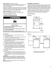
... recommended to reduce noise transfer. ■■ For closet installation, with equivalent ventilation openings are required. Dryer Dimensions Front View 29" (737 mm) 407/8" (1038 mm) Gas and Electric Dryer PRODUCT MODEL NUMBERS WED7000D, WED7300D, WGD7000D, WGD7300D Side View 503/4" (1289 mm) 281/4" (717 mm) 42" (1067 mm) 281/4" (717 mm) 1/2" (13...
... recommended to reduce noise transfer. ■■ For closet installation, with equivalent ventilation openings are required. Dryer Dimensions Front View 29" (737 mm) 407/8" (1038 mm) Gas and Electric Dryer PRODUCT MODEL NUMBERS WED7000D, WED7300D, WGD7000D, WGD7300D Side View 503/4" (1289 mm) 281/4" (717 mm) 42" (1067 mm) 281/4" (717 mm) 1/2" (13...
Dimension Guide
Page 2
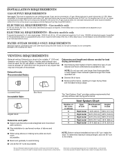
...hood combinations acceptable to change without notice. A time-delay fuse or circuit breaker is required. VENTING REQUIREMENTS Exhaust venting: Exhaust your dryer to an individual branch circuit. Louvered Hood Acceptable Style: Box Hood Angled Hood Determine vent path: ■■ Select route ... path outdoors. ■■ Plan installation to avoid kinking. ■■ Use as few 90° turns as possible. Because Whirlpool Corporation policy includes a continuous commitment to improve our products, we reserve the right to use old hoses. The "Vent System Chart" ...
...hood combinations acceptable to change without notice. A time-delay fuse or circuit breaker is required. VENTING REQUIREMENTS Exhaust venting: Exhaust your dryer to an individual branch circuit. Louvered Hood Acceptable Style: Box Hood Angled Hood Determine vent path: ■■ Select route ... path outdoors. ■■ Plan installation to avoid kinking. ■■ Use as few 90° turns as possible. Because Whirlpool Corporation policy includes a continuous commitment to improve our products, we reserve the right to use old hoses. The "Vent System Chart" ...
Installation Guide
Page 2
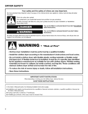
DRYER SAFETY 2
DRYER SAFETY 2
Installation Guide
Page 4
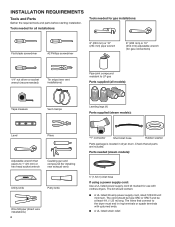
... (all models): Tape measure Vent clamps Leveling legs (4) Parts supplied (steam models): Level Pliers Adjustable wrench that opens to the dryer must end in dryer drum. The cord should contain: ■■ A UL listed 30-amp power supply cord, rated 120/240 volt minimum. ...Wire Stripper (direct wire installations) 4 "Y" connector Short inlet hose Rubber washer Parts package is located in ring terminals or spade terminals with clothes dryers. Check that connect to 1" (25 mm) or hex-head socket wrench Caulking gun and compound (for use with upturned ends. ■■...
... (all models): Tape measure Vent clamps Leveling legs (4) Parts supplied (steam models): Level Pliers Adjustable wrench that opens to the dryer must end in dryer drum. The cord should contain: ■■ A UL listed 30-amp power supply cord, rated 120/240 volt minimum. ...Wire Stripper (direct wire installations) 4 "Y" connector Short inlet hose Rubber washer Parts package is located in ring terminals or spade terminals with clothes dryers. Check that connect to 1" (25 mm) or hex-head socket wrench Caulking gun and compound (for use with upturned ends. ■■...
Installation Guide
Page 5
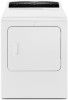
...Care Guide." If not level, clothes may not tumble properly and automatic sensor cycles may not operate correctly. ■■ For garage installation, place dryer at least 18" (460 mm) above floor. ■■ Steam models only: Cold water faucets located within 2 ft. (610 mm) ...: No other fuel-burning appliance can be installed in garages, closets, mobile homes, or sleeping quarters. IMPORTANT: Do not operate, install, or store dryer where it will need: ■■ A location allowing for proper exhaust installation. Some codes limit, or do not permit, installation of 200 lbs....
...Care Guide." If not level, clothes may not tumble properly and automatic sensor cycles may not operate correctly. ■■ For garage installation, place dryer at least 18" (460 mm) above floor. ■■ Steam models only: Cold water faucets located within 2 ft. (610 mm) ...: No other fuel-burning appliance can be installed in garages, closets, mobile homes, or sleeping quarters. IMPORTANT: Do not operate, install, or store dryer where it will need: ■■ A location allowing for proper exhaust installation. Some codes limit, or do not permit, installation of 200 lbs....
Installation Guide
Page 6
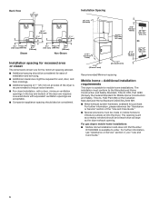
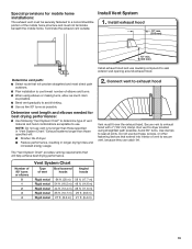
... required for wall, door, and floor moldings. ■■ Additional spacing of 1" (25 mm) on all sides of the dryer is recommended to reduce noise transfer. ■■ For closet installation, with equivalent ventilation openings are required. The opening (such as the...section of the door are acceptable. ■■ Companion appliance spacing should be made in your "Use and Care Guide." 6 For gas dryers mobile home installations: ■■ Mobile Home Installation Hold-down Kit Part Number W10432680 is suitable for purchase. Installation Spacing 14" max (...
... required for wall, door, and floor moldings. ■■ Additional spacing of 1" (25 mm) on all sides of the dryer is recommended to reduce noise transfer. ■■ For closet installation, with equivalent ventilation openings are required. The opening (such as the...section of the door are acceptable. ■■ Companion appliance spacing should be made in your "Use and Care Guide." 6 For gas dryers mobile home installations: ■■ Mobile Home Installation Hold-down Kit Part Number W10432680 is suitable for purchase. Installation Spacing 14" max (...
Installation Guide
Page 7
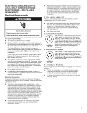
...ground conductor) may be using a power supply cord: Use a UL listed power supply cord kit marked for homes built after 1996, dryer circuits involved in conformance with a 4-wire electrical supply connection, the neutral ground conductor must be removed from the external ground connector (green ...- ÉTATS-UNIS SEULEMENT) Electrical Requirements ■■ A 4-wire power supply connection must be used , it here. ■■ This dryer is your dryer, you must be at least 4 ft. (1.22 m) long, must have 4 10-gauge solid copper wires and match a 4-wire receptacle of ...
...ground conductor) may be using a power supply cord: Use a UL listed power supply cord kit marked for homes built after 1996, dryer circuits involved in conformance with a 4-wire electrical supply connection, the neutral ground conductor must be removed from the external ground connector (green ...- ÉTATS-UNIS SEULEMENT) Electrical Requirements ■■ A 4-wire power supply connection must be used , it here. ■■ This dryer is your dryer, you must be at least 4 ft. (1.22 m) long, must have 4 10-gauge solid copper wires and match a 4-wire receptacle of ...
Installation Guide
Page 8
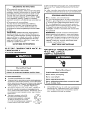
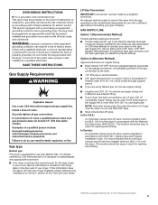
...your responsibility: ■■ To contact a qualified electrical installer. ■■ To be sure that a separate circuit serving only this dryer be provided. 8 Check with Canadian Electrical Code, C22.1-latest edition and all local codes and ordinances. A copy of above codes standard .... Do not remove ground prong. Be sure wall receptacle is recommended. or 20- GROUNDING INSTRUCTIONS I For a grounded, cord-connected dryer: This dryer must be grounded. It is also recommended that the electrical connection is adequate and in a risk of electric shock. If using a...
...your responsibility: ■■ To contact a qualified electrical installer. ■■ To be sure that a separate circuit serving only this dryer be provided. 8 Check with Canadian Electrical Code, C22.1-latest edition and all local codes and ordinances. A copy of above codes standard .... Do not remove ground prong. Be sure wall receptacle is recommended. or 20- GROUNDING INSTRUCTIONS I For a grounded, cord-connected dryer: This dryer must be grounded. It is also recommended that the electrical connection is adequate and in a risk of electric shock. If using a...
Installation Guide
Page 9
..., grounding will not t the outlet, have the correct burner for LP (propane or butane) gases with a different gas without consulting your dryer has been converted to use LP gas, 3/8" LP compatible copper tubing can result in a risk of the equipment- Check with a cord ...rating plate for use a new flexible stainless steel gas connector (Design Certified by the American Gas Association or CSA International) to connect your dryer to the dryer. ■■ 1/2" IPS pipe is recommended. ■■ 3/8" approved aluminum or copper tubing is designcertified by providing a path of...
..., grounding will not t the outlet, have the correct burner for LP (propane or butane) gases with a different gas without consulting your dryer has been converted to use LP gas, 3/8" LP compatible copper tubing can result in a risk of the equipment- Check with a cord ...rating plate for use a new flexible stainless steel gas connector (Design Certified by the American Gas Association or CSA International) to connect your dryer to the dryer. ■■ 1/2" IPS pipe is recommended. ■■ 3/8" approved aluminum or copper tubing is designcertified by providing a path of...
Installation Guide
Page 10
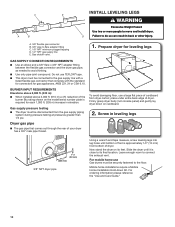
... Installation Hold-down on cardboard. 2. Gas shutoff valve. 1. To avoid damaging floor, use TEFLON® tape. ■■ This dryer must be connected to its feet. Leave enough room to flare adapter fitting C. 1/8" NPT minimum plugged tapping D. 1/2" NPT gas supply ...line E. place under entire back edge of dryer. For ordering information please reference the "Use and Care Guide." 10 INSTALL LEVELING LEGS C E A B D A. 3/8" flexible gas connector B. ...
... Installation Hold-down on cardboard. 2. Gas shutoff valve. 1. To avoid damaging floor, use TEFLON® tape. ■■ This dryer must be connected to its feet. Leave enough room to flare adapter fitting C. 1/8" NPT minimum plugged tapping D. 1/2" NPT gas supply ...line E. place under entire back edge of dryer. For ordering information please reference the "Use and Care Guide." 10 INSTALL LEVELING LEGS C E A B D A. 3/8" flexible gas connector B. ...
Installation Guide
Page 12
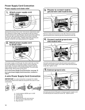
... sure that one tab is pointing up (A) and the other is inside the strain relief. Tighten screw. 5. Ground prong D. Neutral prong E. Spade terminals with the dryer cabinet and be in place. Power Supply Cord Connection Power supply cord strain relief 1. E A B Remove the screws from external ground conductor screw (A). 4. C. G. Connect neutral ground...
... sure that one tab is pointing up (A) and the other is inside the strain relief. Tighten screw. 5. Ground prong D. Neutral prong E. Spade terminals with the dryer cabinet and be in place. Power Supply Cord Connection Power supply cord strain relief 1. E A B Remove the screws from external ground conductor screw (A). 4. C. G. Connect neutral ground...
Installation Guide
Page 13
...a tight fit with upturned ends E. 3/4" (19 mm) UL listed strain relief F. Tighten strain relief screws. Finally, reinsert tab of terminal block cover into slot of dryer rear panel. C. Neutral prong D. Neutral (white or center wire) 3. Finally, reinsert tab of terminal block cover into slot of... dryer rear panel. Tighten screw. Secure cover with hold -down screw. Put the threaded section of power supply cord to neutral wire. Tighten screws. Secure ...
...a tight fit with upturned ends E. 3/4" (19 mm) UL listed strain relief F. Tighten strain relief screws. Finally, reinsert tab of terminal block cover into slot of dryer rear panel. C. Neutral prong D. Neutral (white or center wire) 3. Finally, reinsert tab of terminal block cover into slot of... dryer rear panel. Tighten screw. Secure cover with hold -down screw. Put the threaded section of power supply cord to neutral wire. Tighten screws. Secure ...
Installation Guide
Page 14
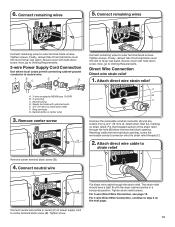
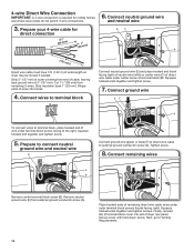
... wires to terminal block, place hooked end of wire under terminal block screw, facing to Venting Requirements. 14 Shape ends of wires into slot of dryer rear panel. Prepare to connect neutral ground wire and neutral wire E Connect ground wire (green or bare) (F) of direct wire cable to terminal block Connect... is required for direct connection EC 31 (89 ⁄2" mm) (251"mm) B (127 5" mm) Direct wire cable must have 5 ft. (1.52 m) of extra length so dryer may be moved if needed.
... wires to terminal block, place hooked end of wire under terminal block screw, facing to Venting Requirements. 14 Shape ends of wires into slot of dryer rear panel. Prepare to connect neutral ground wire and neutral wire E Connect ground wire (green or bare) (F) of direct wire cable to terminal block Connect... is required for direct connection EC 31 (89 ⁄2" mm) (251"mm) B (127 5" mm) Direct wire cable must have 5 ft. (1.52 m) of extra length so dryer may be moved if needed.
Installation Guide
Page 15
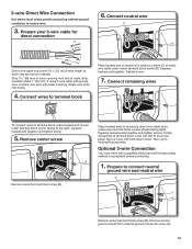
...Place hooked ends of direct wire cable under center terminal block screw (B). Secure cover with outer covering. Remove neutral ground wire (E) from end of dryer rear panel. Connect neutral wire C 3. Strip 31/2" (89 mm) of outer covering from external ground conductor screw (A). 15 Connect wires to...wire. 6. Shape wire ends into slot of cable. Connect remaining wires To connect wires to terminal block, place hooked end of extra length so dryer may be moved if needed. Remove center screw B Remove center terminal block screw (B). Optional 3-wire Connection You must have 5 ft. (1.52 ...
...Place hooked ends of direct wire cable under center terminal block screw (B). Secure cover with outer covering. Remove neutral ground wire (E) from end of dryer rear panel. Connect neutral wire C 3. Strip 31/2" (89 mm) of outer covering from external ground conductor screw (A). 15 Connect wires to...wire. 6. Shape wire ends into slot of cable. Connect remaining wires To connect wires to terminal block, place hooked end of extra length so dryer may be moved if needed. Remove center screw B Remove center terminal block screw (B). Optional 3-wire Connection You must have 5 ft. (1.52 ...
Installation Guide
Page 16
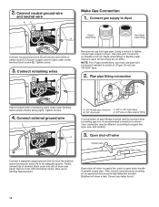
...Connect gas supply to supply line type, size, and location. 3. NOTE: For LP gas connections, you must be different, according to dryer Flared B maAle fitting mNoalne-fflBiattriendg Connect neutral ground wire (E) and neutral wire (white or center wire) (C) of all non-flared ...male fittings. Connect external ground wire E A A. 3/8" flexible gas connector C. 3/8" to 3/8" pipe elbow B. 3/8" dryer pipe D. 3/8" pipe-to existing gas line. Then, test all connections by brushing on threads of power supply cord or cable under outer terminal block screws...
...Connect gas supply to supply line type, size, and location. 3. NOTE: For LP gas connections, you must be different, according to dryer Flared B maAle fitting mNoalne-fflBiattriendg Connect neutral ground wire (E) and neutral wire (white or center wire) (C) of all non-flared ...male fittings. Connect external ground wire E A A. 3/8" flexible gas connector C. 3/8" to 3/8" pipe elbow B. 3/8" dryer pipe D. 3/8" pipe-to existing gas line. Then, test all connections by brushing on threads of power supply cord or cable under outer terminal block screws...

Installation Guide
Page 17
...: ■■ Use clamps to avoid sagging and kinking that may be connected or secured with rigid metal or flexible metal vents. Dryer exhaust must not be used for more information. 17 Do not use plastic or metal foil vent. Only rigid or flexible metal vent ...an existing vent system, clean lint from ground or any gas vent, chimney, wall, ceiling, attic, crawlspace, or a concealed space of fire, this dryer MUST BE EXHAUSTED OUTDOORS. VENTING Venting Requirements Exhaust hoods: ■■ Must be used . ■■ Do not use duct tape. Recommended Styles:...
...: ■■ Use clamps to avoid sagging and kinking that may be connected or secured with rigid metal or flexible metal vents. Dryer exhaust must not be used for more information. 17 Do not use plastic or metal foil vent. Only rigid or flexible metal vent ...an existing vent system, clean lint from ground or any gas vent, chimney, wall, ceiling, attic, crawlspace, or a concealed space of fire, this dryer MUST BE EXHAUSTED OUTDOORS. VENTING Venting Requirements Exhaust hoods: ■■ Must be used . ■■ Do not use duct tape. Recommended Styles:...
Installation Guide
Page 18
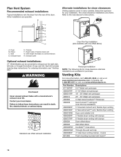
...Clamps F. Exhaust outlet Optional exhaust installations: 27" Wide Models can be converted to connect elbows H. Select the type best for purchase. Dryer B. Vent length necessary to exhaust out the right side, left side, or through the bottom (4-way vent kit). Two close elbow ...4396007RW Through-the-wall vent cap 4396008RP 4" steel dryer venting clamps - 2 pack 8212662 Flush mounting louvered vent hood 4" 18 Refer to the manufacturer's instructions. Other installations are shown. Exhaust hood...
...Clamps F. Exhaust outlet Optional exhaust installations: 27" Wide Models can be converted to connect elbows H. Select the type best for purchase. Dryer B. Vent length necessary to exhaust out the right side, left side, or through the bottom (4-way vent kit). Two close elbow ...4396007RW Through-the-wall vent cap 4396008RP 4" steel dryer venting clamps - 2 pack 8212662 Flush mounting louvered vent hood 4" 18 Refer to the manufacturer's instructions. Other installations are shown. Exhaust hood...
Installation Guide
Page 19
... of elbows and turns. ■■ When using straightest path possible. The "Vent System Chart" provides venting requirements that will : ■■ Shorten life of dryer. ■■ Reduce performance, resulting in "Vent System Chart." Avoid 90° turns. Number of 90° turns or elbows 0 1 2 3 4 Vent System Chart Type of...;■ Use as few 90° turns as possible. ■■ Bend vent gradually to seal exterior wall opening around exhaust hood. Run vent to dryer location using elbows or making turns, allow as much room as possible.
... of elbows and turns. ■■ When using straightest path possible. The "Vent System Chart" provides venting requirements that will : ■■ Shorten life of dryer. ■■ Reduce performance, resulting in "Vent System Chart." Avoid 90° turns. Number of 90° turns or elbows 0 1 2 3 4 Vent System Chart Type of...;■ Use as few 90° turns as possible. ■■ Bend vent gradually to seal exterior wall opening around exhaust hood. Run vent to dryer location using elbows or making turns, allow as much room as possible.
Installation Guide
Page 20
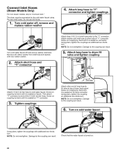
... long hose to "Y" connector and tighten couplings Turn cold water faucet off , remove and replace rubber washer 4. Attach short hose and "Y" connector Attach dryer 5 ft (1.5 m) inlet hose ends to the cold water faucet using the new inlet hoses. Attach washer cold inlet hose to other end of... from inlet hose and replace with additional two-thirds turn . Screw on coupling by hand until it is seated on connector. Attach long hose to dryer fill valve and tighten coupling 301/4" (768 mm) Attach 2 ft (0.6 m) inlet hose to "Connect Vent." Screw on coupling by hand until it is ...
... long hose to "Y" connector and tighten couplings Turn cold water faucet off , remove and replace rubber washer 4. Attach short hose and "Y" connector Attach dryer 5 ft (1.5 m) inlet hose ends to the cold water faucet using the new inlet hoses. Attach washer cold inlet hose to other end of... from inlet hose and replace with additional two-thirds turn . Screw on coupling by hand until it is seated on connector. Attach long hose to dryer fill valve and tighten coupling 301/4" (768 mm) Attach 2 ft (0.6 m) inlet hose to "Connect Vent." Screw on coupling by hand until it is ...
Installation Guide
Page 22
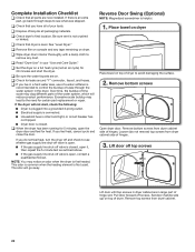
... time, the buildup of lime scale may lead to the need for certain part replacement or repair. If you do not remove) top screws from dryer cabinet side of hinges. 3. The odor will go back through the water system in a hard water area, use of a water softener is helpful. 1. Remove ...bottom screws from dryer cabinet. 22 Set door (handle side up) on . See "Level Dryer." q When the dryer has been running for heat. This odor is common when the heating element is an extra part, go away...
... time, the buildup of lime scale may lead to the need for certain part replacement or repair. If you do not remove) top screws from dryer cabinet side of hinges. 3. The odor will go back through the water system in a hard water area, use of a water softener is helpful. 1. Remove ...bottom screws from dryer cabinet. 22 Set door (handle side up) on . See "Level Dryer." q When the dryer has been running for heat. This odor is common when the heating element is an extra part, go away...


